Product Description
Stainless Steel 304 Inox Gear Box Hygienic Reductor Sea Food Machinery Helical Bevel Geared Electric Motor Reducer
Product Description
1. Light in weight and non-rusting.
2. Smooth in running, can work a long time in dreadful conditions.
3. High efficiency, low noise.
4. Good-looking in appearance, durable in service life, and small in volume.
Detailed Photos
Product Parameters
| Stainless Steel Gearbox Model | 030 ~ 090 |
| Power | 0.06kw ~ 4kw |
| Input speed | 750rpm ~ 2000rpm |
| Reduction ratio | 1/5 ~ 1/100 |
| Input motor | AC (1 phase or 3 phase) / DC / BLDC / Stepper / Servo |
| Output shaft | Solid shaft / Hollow shaft / Output flange… |
| Dimension standard | Metric size / Inch size |
| Material of housing | Stainless steel 304 |
| Accessories | Flange / CHINAMFG shaft / Torque arm / Cover … |
| Stainless Steel Motor Power | 1/4HP~30HP |
| Frame Size | IEC 63 ~ 180 B5 B14, NEMA 56 ~ 286TC |
| Motor Phase | Single or Three |
| Voltage | (208-230)230/460V |
| Poles | 2, 4, 6, 8 poles |
| Protection Class | IP69K |
| Cooling method | TENV or TEFC |
| Mounting Type | B14, B3, B5, B35, B34 |
| Ambient Temperature | -15 ~ +40 °C |
| Altitude | ≤1000M |
| Material | Stainless steel 304 |
Typical applications
Company Profile
Certifications
FAQ
Q: Can you make the reducer with customization?
A: Yes, we can customize per your request, like flange, shaft, configuration, material, etc.
Q: Do you provide samples?
A: Yes. A sample is available for testing.
Q: What’s your lead time?
A: Standard products need 5-30 days, a bit longer for customized products.
Q: Do you provide technical support?
A: Yes. Our company has a design and development team, we can provide technical support if you
need.
Q: How to ship to us?
A: It is available by air, by sea, or by train.
Q: How to pay the money?
A: T/T and L/C are preferred, with a different currency, including USD, EUR, RMB, etc.
Q: How can I know if the product is suitable for me?
A: >1ST confirm drawing and specification >2nd test sample >3rd start mass production.
Q: Can I come to your company to visit?
A: Yes, you are welcome to visit us at any time.
Q: How shall we contact you?
A: You can send an inquiry directly, and we will respond within 24 hours. /* January 22, 2571 19:08:37 */!function(){function s(e,r){var a,o={};try{e&&e.split(“,”).forEach(function(e,t){e&&(a=e.match(/(.*?):(.*)$/))&&1
| Application: | Motor, Machinery, Marine, Agricultural Machinery |
|---|---|
| Function: | Distribution Power, Change Drive Torque, Change Drive Direction, Speed Changing, Speed Reduction, Speed Increase |
| Layout: | Right Angle |
| Samples: |
US$ 200/Piece
1 Piece(Min.Order) | Order Sample 1 pc per carton
|
|---|
| Customization: |
Available
| Customized Request |
|---|
.shipping-cost-tm .tm-status-off{background: none;padding:0;color: #1470cc}
|
Shipping Cost:
Estimated freight per unit. |
about shipping cost and estimated delivery time. |
|---|
| Payment Method: |
|
|---|---|
|
Initial Payment Full Payment |
| Currency: | US$ |
|---|
| Return&refunds: | You can apply for a refund up to 30 days after receipt of the products. |
|---|
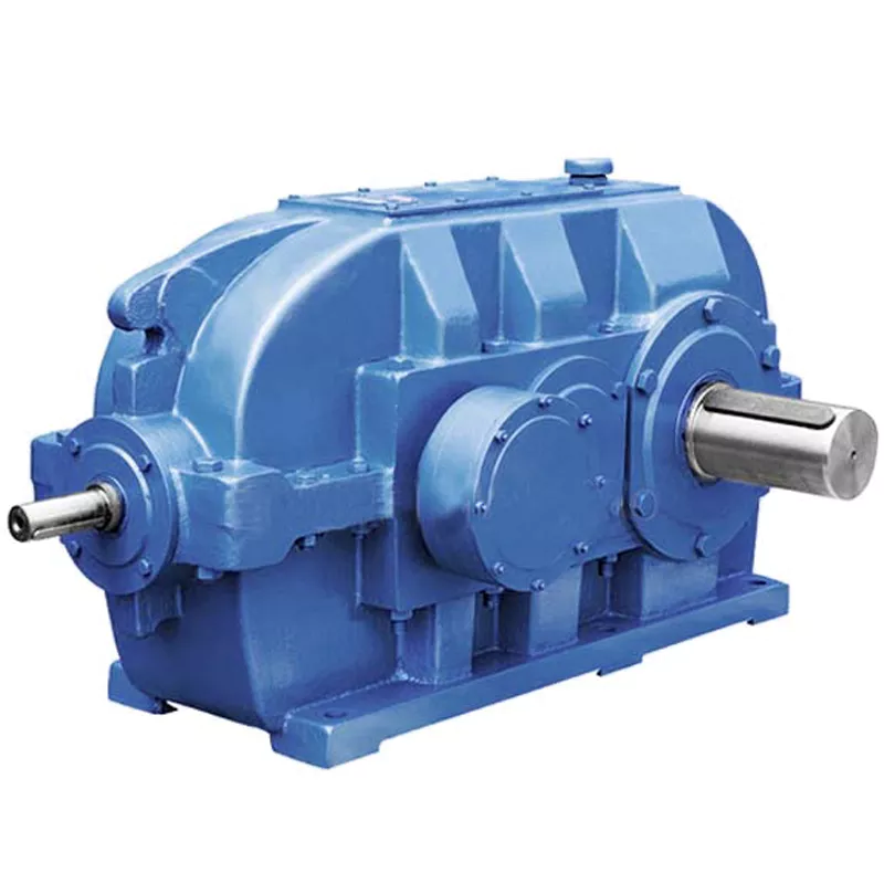
How do gear reducers enhance the efficiency of conveyor systems and robotics?
Gear reducers play a significant role in improving the efficiency of both conveyor systems and robotics by optimizing speed, torque, and control. Here’s how they contribute:
Conveyor Systems:
In conveyor systems, gear reducers enhance efficiency in the following ways:
- Speed Control: Gear reducers allow precise control over the rotational speed of conveyor belts, ensuring that materials are transported at the desired speed for efficient production processes.
- Torque Adjustment: By adjusting gear ratios, gear reducers provide the necessary torque to handle varying loads and prevent overloading, minimizing energy wastage.
- Reverse Operation: Gear reducers enable smooth bidirectional movement of conveyor belts, facilitating tasks such as loading, unloading, and distribution without the need for additional components.
- Synchronization: Gear reducers ensure synchronized movement of multiple conveyor belts in complex systems, optimizing material flow and minimizing jams or bottlenecks.
Robotics:
In robotics, gear reducers enhance efficiency through the following means:
- Precision Movement: Gear reducers provide precise control over the movement of robot joints and arms, enabling accurate positioning and manipulation of objects.
- Reduced Inertia: Gear reducers help reduce the inertia experienced by robotic components, allowing for quicker and more responsive movements while conserving energy.
- Compact Design: Gear reducers offer a compact and lightweight solution for achieving various motion profiles in robotic systems, allowing for efficient use of space and resources.
- Torque Amplification: By amplifying torque from the motor, gear reducers enable robots to handle heavier loads and perform tasks that require greater force, enhancing their overall capabilities.
By providing precise speed control, torque adjustment, and reliable motion transmission, gear reducers optimize the performance of conveyor systems and robotics, leading to improved efficiency, reduced energy consumption, and enhanced operational capabilities.
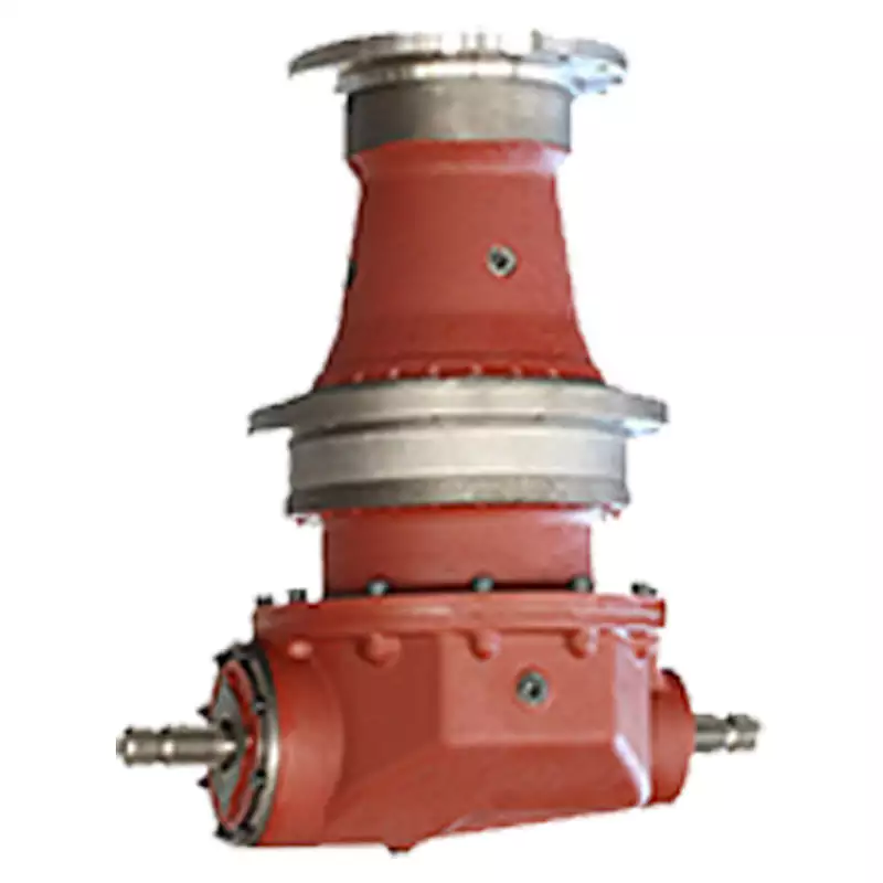
What maintenance practices are essential for prolonging the lifespan of gear reducers?
Proper maintenance is crucial for extending the lifespan and ensuring optimal performance of gear reducers. Here are essential maintenance practices:
- 1. Lubrication: Regular lubrication of gear reducers is vital to reduce friction, wear, and heat generation. Use the recommended lubricant and follow the manufacturer’s guidelines for lubrication intervals.
- 2. Inspection: Routinely inspect gear reducers for signs of wear, damage, or leaks. Check for unusual noises, vibrations, or temperature increases during operation.
- 3. Alignment: Ensure proper alignment of the input and output shafts. Misalignment can lead to increased wear, noise, and reduced efficiency. Align the components according to the manufacturer’s specifications.
- 4. Cooling and Ventilation: Maintain proper cooling and ventilation to prevent overheating. Ensure that cooling fans and vents are clean and unobstructed.
- 5. Seal Maintenance: Inspect and replace seals as needed to prevent contaminants from entering the gear reducer. Contaminants can lead to accelerated wear and reduced performance.
- 6. Bolts and Fasteners: Regularly check and tighten bolts and fasteners to prevent loosening during operation, which can cause misalignment or component damage.
- 7. Replacing Worn Components: Replace worn or damaged components, such as gears, bearings, and seals, with genuine parts from the manufacturer.
- 8. Vibration Analysis: Conduct periodic vibration analysis to identify potential issues early. Excessive vibration can indicate misalignment or component wear.
- 9. Maintenance Records: Keep detailed maintenance records, including lubrication schedules, inspection dates, and component replacements. This helps track the history of the gear reducer and aids in future maintenance planning.
- 10. Training: Provide proper training to maintenance personnel on gear reducer maintenance and troubleshooting techniques.
By adhering to these maintenance practices, you can maximize the lifespan of your gear reducers, minimize downtime, and ensure reliable operation in your industrial processes.
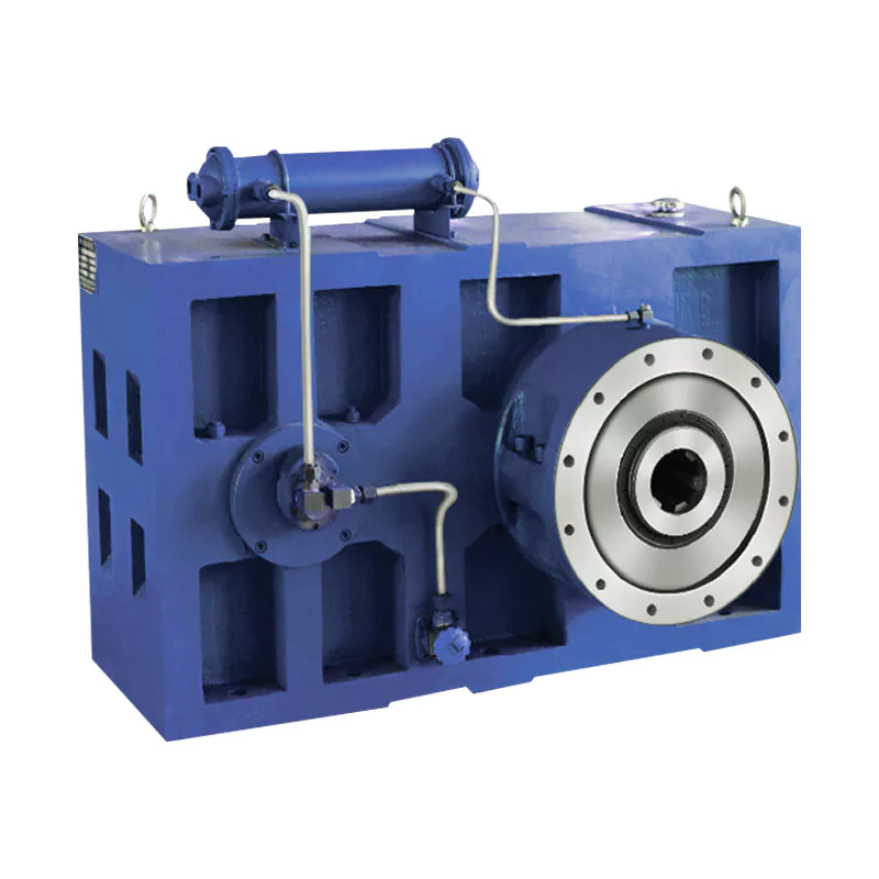
What industries and machinery commonly utilize gear reducers?
Gear reducers are widely used across various industries and types of machinery for torque reduction and speed control. Some common industries and applications include:
- 1. Manufacturing: Gear reducers are used in manufacturing equipment such as conveyors, mixers, and packaging machines to control speed and transmit power efficiently.
- 2. Automotive: They are utilized in vehicles for applications like power transmission in transmissions and differentials.
- 3. Aerospace: Gear reducers are used in aircraft systems, including landing gear mechanisms and engine accessories.
- 4. Robotics and Automation: They play a crucial role in robotic arms, CNC machines, and automated production lines.
- 5. Mining and Construction: Gear reducers are used in heavy machinery like excavators, bulldozers, and crushers for power transmission and torque multiplication.
- 6. Energy and Power Generation: Wind turbines, hydroelectric generators, and other power generation equipment use gear reducers to convert rotational speed and transmit power.
- 7. Marine and Shipbuilding: They are used in ship propulsion systems, steering mechanisms, and anchor handling equipment.
- 8. Material Handling: Gear reducers are essential in conveyor systems, elevators, and hoists for controlled movement of materials.
- 9. Food and Beverage: They find applications in food processing equipment like mixers, grinders, and packaging machines.
- 10. Paper and Pulp: Gear reducers are used in machinery for pulp processing, paper production, and printing.
These examples represent just a fraction of the industries and machinery that benefit from the use of gear reducers to optimize power transmission and achieve the desired motion characteristics.


editor by CX 2024-04-26
China Custom Best Price Machinery Agricultural Cycloidal Gearbox Gear Motor Speed Reducer manufacturer
Product Description
GRH specialized in providing hydraulic components and solutions for hydraulic systems.
With continuous improvement and enthusiasm over the past 30 years, CHINAMFG has developed into an emerging power in the fluid power industry since it was established in 1986.
GRH (ZheJiang ) – International Sales Office
GRH (ZheJiang ) – Manufacturing Facility and Domestic Sales Office
—————————————————————————————————————————————————
Production description
| We can produce motor according to your needs ! |
About Us
Application and Partners
Contact us!
/* January 22, 2571 19:08:37 */!function(){function s(e,r){var a,o={};try{e&&e.split(“,”).forEach(function(e,t){e&&(a=e.match(/(.*?):(.*)$/))&&1
| Application: | Motor, Machinery, Agricultural Machinery |
|---|---|
| Hardness: | Hardened Tooth Surface |
| Installation: | Vertical Type |
| Layout: | Expansion |
| Gear Shape: | Conical – Cylindrical Gear |
| Step: | Stepless |
| Samples: |
US$ 1050/Piece
1 Piece(Min.Order) | |
|---|
| Customization: |
Available
| Customized Request |
|---|
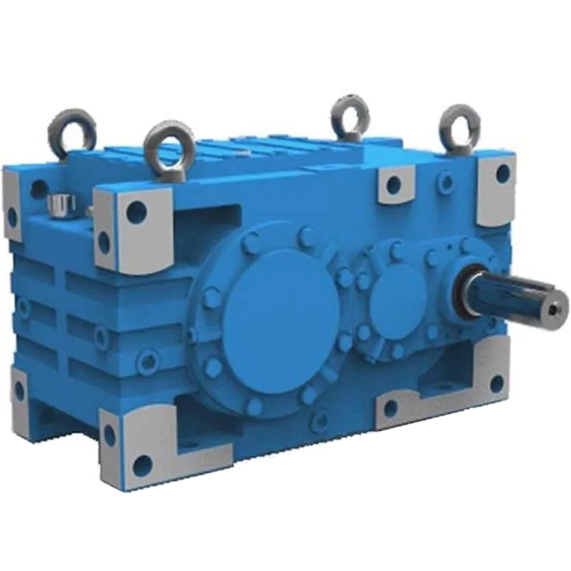
How do gear reducers contribute to energy efficiency in machinery and equipment?
Gear reducers play a significant role in enhancing energy efficiency in various machinery and equipment. Here’s how they contribute:
1. Speed Reduction: Gear reducers are commonly used to reduce the speed of the input shaft, allowing the motor to operate at a higher speed where it’s most efficient. This speed reduction helps match the motor’s optimal operating range, reducing energy consumption.
2. Torque Increase: Gear reducers can increase torque output while decreasing speed, enabling machinery to handle higher loads without the need for a larger, more energy-intensive motor.
3. Matching Load Requirements: By adjusting gear ratios, gear reducers ensure that the machinery’s output speed and torque match the load requirements. This prevents the motor from operating at unnecessary high speeds, saving energy.
4. Variable Speed Applications: In applications requiring variable speeds, gear reducers allow for efficient speed control without the need for continuous motor adjustments, improving energy usage.
5. Efficient Power Transmission: Gear reducers efficiently transmit power from the motor to the load, minimizing energy losses due to friction and inefficiencies.
6. Motor Downsizing: Gear reducers enable the use of smaller, more energy-efficient motors by converting their higher speed, lower torque output into the lower speed, higher torque needed for the application.
7. Decoupling Motor and Load Speeds: In cases where the motor and load speeds are inherently different, gear reducers ensure the motor operates at its most efficient speed while still delivering the required output to the load.
8. Overcoming Inertia: Gear reducers help overcome the inertia of heavy loads, making it easier for motors to start and stop, reducing energy consumption during frequent operation.
9. Precise Control: Gear reducers provide precise control over speed and torque, optimizing the energy consumption of machinery in processes that require accurate adjustments.
10. Regenerative Braking: In some applications, gear reducers can be used to capture and convert kinetic energy back into electrical energy during braking or deceleration, improving overall energy efficiency.
By efficiently managing speed, torque, and power transmission, gear reducers contribute to energy-efficient operation, reducing energy consumption, and minimizing the environmental impact of machinery and equipment.
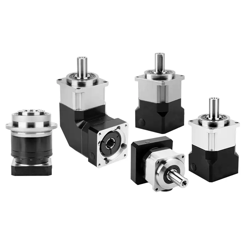
Can gear reducers be used for both speed reduction and speed increase?
Yes, gear reducers can be utilized for both speed reduction and speed increase, depending on their design and arrangement. The functionality to either decrease or increase rotational speed is achieved by altering the arrangement of gears within the gearbox.
1. Speed Reduction: In speed reduction applications, a gear reducer is designed with gears of different sizes. The input shaft connects to a larger gear, while the output shaft is connected to a smaller gear. As the input shaft rotates, the larger gear turns the smaller gear, resulting in a decrease in output speed compared to the input speed. This configuration provides higher torque output at a lower speed, making it suitable for applications that require increased force or torque.
2. Speed Increase: For speed increase, the gear arrangement is reversed. The input shaft connects to a smaller gear, while the output shaft is connected to a larger gear. As the input shaft rotates, the smaller gear drives the larger gear, resulting in an increase in output speed compared to the input speed. However, the torque output is lower than that of speed reduction configurations.
By choosing the appropriate gear ratios and arrangement, gear reducers can be customized to meet specific speed and torque requirements for various industrial applications. It’s important to select the right type of gear reducer and configure it correctly to achieve the desired speed reduction or speed increase.

What industries and machinery commonly utilize gear reducers?
Gear reducers are widely used across various industries and types of machinery for torque reduction and speed control. Some common industries and applications include:
- 1. Manufacturing: Gear reducers are used in manufacturing equipment such as conveyors, mixers, and packaging machines to control speed and transmit power efficiently.
- 2. Automotive: They are utilized in vehicles for applications like power transmission in transmissions and differentials.
- 3. Aerospace: Gear reducers are used in aircraft systems, including landing gear mechanisms and engine accessories.
- 4. Robotics and Automation: They play a crucial role in robotic arms, CNC machines, and automated production lines.
- 5. Mining and Construction: Gear reducers are used in heavy machinery like excavators, bulldozers, and crushers for power transmission and torque multiplication.
- 6. Energy and Power Generation: Wind turbines, hydroelectric generators, and other power generation equipment use gear reducers to convert rotational speed and transmit power.
- 7. Marine and Shipbuilding: They are used in ship propulsion systems, steering mechanisms, and anchor handling equipment.
- 8. Material Handling: Gear reducers are essential in conveyor systems, elevators, and hoists for controlled movement of materials.
- 9. Food and Beverage: They find applications in food processing equipment like mixers, grinders, and packaging machines.
- 10. Paper and Pulp: Gear reducers are used in machinery for pulp processing, paper production, and printing.
These examples represent just a fraction of the industries and machinery that benefit from the use of gear reducers to optimize power transmission and achieve the desired motion characteristics.


editor by CX 2024-03-26
China Good quality CZPT Machinery Planetary Reducer Gearbox Speed Reducer for Motor cycloidal gearbox efficiency
Product Description
GRH specialized in providing hydraulic components and solutions for hydraulic systems.
With continuous improvement and enthusiasm over the past 30 years, CZPT has developed into an emerging power in the fluid power industry since it was established in 1986.
GRH (ZheJiang ) – International Sales Office
GRH (ZheJiang ) – Manufacturing Facility and Domestic Sales Office
—————————————————————————————————————————————————
Production description
| We can produce motor according to your needs ! |
About Us
Application and Partners
Contact us!
| Application: | Motor, Machinery, Agricultural Machinery |
|---|---|
| Hardness: | Hardened Tooth Surface |
| Installation: | Vertical Type |
| Layout: | Expansion |
| Gear Shape: | Conical – Cylindrical Gear |
| Step: | Stepless |
| Samples: |
US$ 1050/Piece
1 Piece(Min.Order) | |
|---|
| Customization: |
Available
| Customized Request |
|---|
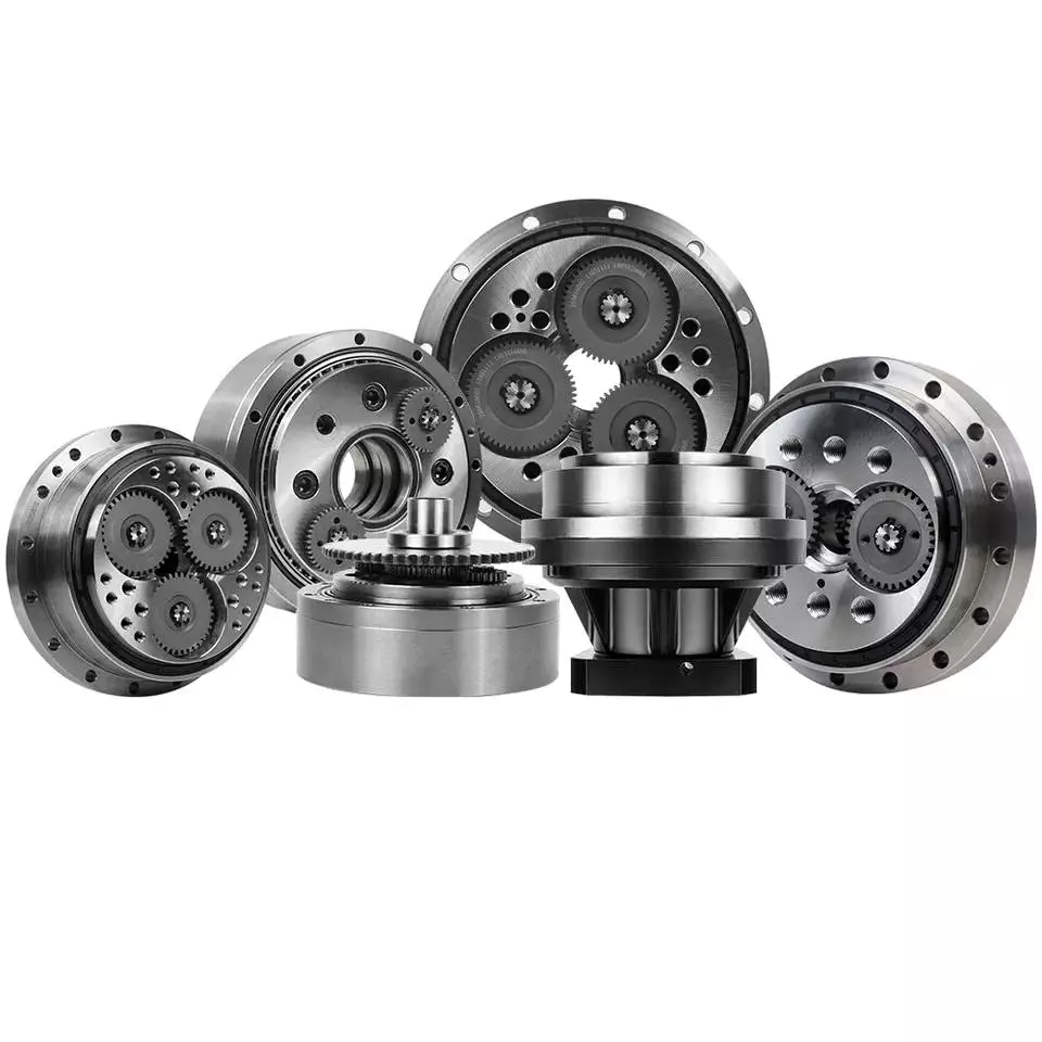
The Basics of Designing a Cyclone Gearbox
Compared to conventional gearboxes, the cycloidal gearbox offers a number of advantages including a higher ratio of transmission, robustness against shock loads, and greater positioning accuracy. However, designing a cycloidal gearbox can be complicated. This article will discuss some of the basic design principles. In addition, it will cover topics such as size, position accuracy, and transmission ratios.
Basic design principles
Unlike a conventional ring gear, a cycloidal gearbox uses a cycloidal disc to provide torque multiplication. The output direction of the cycloidal gear disc is opposite to the rotation of the input shaft. This allows for more compact gear construction. It also allows for increased load capacity.
Cycloid drive kinematics can appear complex, but they are actually quite simple. Instead of rotating around the center of gravity like conventional gears, the cycloidal disc rotates around fixed pins. This provides a higher reduction ratio.
To reduce vibrations and noise, multiple cycloidal discs are used. This allows for uniform distribution of forces on the carrier pin devices. This also provides a better rotational balance. In addition, multiple cycloidal discs reduce the axial moment of the carrier pin devices.
The cycloidal gear disc is supported by a separate gear disc bearing. This design provides a low component count and reduces wear. This type of kinematics can also be used in an electric motor with a high power density.
The cycloidal gear disc provides a high reduction ratio, which allows for compact construction. Unlike a ring gear, the cycloidal disc has fewer teeth. It also provides a higher reduction ratio, which is advantageous for high rotational input speed applications.
Cycloid gear discs have cylindrical holes, which allow for carrier pin devices to protrude through them. This is useful because the carrier pin devices can roll along the inside wall of the cylindrical hole in the gear disc.
A load plate is also used to provide anchorage for external structures. This plate contains threaded screw holes arranged 15mm away from the center. It has a 9mm external diameter and a 3mm through hole.
Transmission ratios up to 300:1
cycloidal gearboxes are used in a wide range of applications, from machine tools to medical imaging devices. Compared to planetary gearboxes, they offer superior positioning accuracy, torsional stiffness, backlash, and fatigue performance.
Cycloid gearboxes are also capable of transmitting more torque than planetary gears. In addition, they have a lower Hertzian contact stress and higher overload protection. Cycloid gearboxes are able to provide transmission ratios up to 300:1 in a small package.
Cycloid gears also have lower backlash over extended periods, making them an ideal choice for applications with critical positioning accuracy. Cycloid gearboxes also have good wear resistance, as well as low friction. Cycloid gears are lightweight and have good torsional stiffness, making them ideal for applications with heavy loads.
Cycloid gearboxes have several different designs. They can provide transmission ratios up to 300:1 without the need for additional pre-stages. Cycloid gears also require more accurate manufacturing processes than involute gears. Cycloid gearboxes can also be used for applications that require high power consumption, and can withstand shock loads.
Cycloid gearboxes can be adapted to fit most common servomotors. They have a modular design, all-round corrosion protection, and easy installation. Cycloid gears have a radial clamping ring, which reduces inertia by up to 39%.
CZPT Precision Europe GmbH, a subsidiary of CZPT Group, has developed an innovative online configurator to simplify the configuration of gearboxes. CZPT cycloidal gearheads are precision-built, robust, and reliable. They have a two-stage reduction principle, which minimises vibration and provides even force distribution.
Cycloid gears are capable of providing transmission ratios from 30:1 to 300:1. Cycloid gearboxes can achieve high gear ratios because they require fewer moving parts, and they have a low backlash.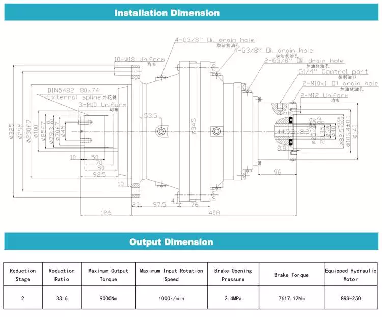
Robustness against shock loads
Unlike conventional gearboxes that are easily damaged by shock loads, the cycloidal gearbox is extremely robust. It is a versatile solution that is ideally suited for handling equipment, food manufacturing, and machine tools.
The mechanical construction of a cycloidal gearbox consists of several mechanical components. These include cycloidal wheels, bearings, transformation elements, and needles. In addition, it has high torsional stiffness and tilting moment. It is also accompanied by highly nonlinear friction characteristic.
In order to assess the robustness of the cycloidal gearbox against shock loads, a mathematical model was developed. The model was used to calculate the stress distribution on the cycloid disc. This model can be used as a basis for more complex mechanical models.
The model is based on new approach, which allows to model stiction in all quadrants of the cycloid gear. In addition, it can be applied to actuator control.
The mathematical model is presented together with the procedure for measuring the contact stress. The results are compared to the measurement performed in the real system. The model and the measurement are found to be very close to each other.
The model also allows for the analysis of different gear profiles for load distribution. In addition, it is possible to analyze contact stresses with different geometric parameters. The mesh refinement along the disc width helps to ensure an even distribution of contact forces.
The stiction breakaway speed is calculated to the motor side. The non-zero current is then derived to the input side of the gearbox. In addition, a small steady phase is modeled during the speed direction transition. The results of the simulation are compared to the measurement. The results show that the model is extremely accurate.
Positioning accuracy
Getting the correct positioning accuracy from a cycloidal gearbox is no small feat. This is because the gears are compact, and the clearances are relatively small. This means you can expect a lot of torque from your output shaft. However, this is only part of the picture. Other concerns, such as backlash, kinematic error, and loading are all important considerations.
Getting the best possible positioning accuracy from a cycloidal gearbox means choosing a reducer that is well-made and correctly configured. A properly-selected reducer will eliminate repeatable inaccuracies and provide absolute positioning accuracy at all times. In addition, this type of gearbox offers several advantages over conventional gearboxes. These include high efficiency, low backlash, and high overload protection.
Getting the correct positioning accuracy from a gearbox also involves choosing a supplier that knows what it is doing. The best vendors are those who have experience with the product, offer a wide variety, and provide support and service to ensure the product is installed and maintained correctly. Another consideration is the manufacturer’s warranty. A reputable manufacturer will offer warranties for the gearbox. The aforementioned factors will ensure that your investment in a cycloidal gearbox pays off for years to come.
Getting the correct positioning accuracy from your cycloidal gearbox involves choosing a manufacturer that specializes in this type of product. This is particularly true if you are involved in robotics, automated painting, or any other industrial process that requires the best possible accuracy. A good manufacturer will offer the latest technology, and have the expertise to help you find the best solution for your application. This will ensure your product is a success from start to finish.
Size
Choosing the right size of cycloidal gearbox is important for its efficient operation. However, it is not a simple task. The process involves complex machining and requires the creation of many parts. There are different sizes of cycloidal gearboxes, and a few basic rules of thumb can help you choose the right size.
The first rule of thumb for choosing the right size of cycloidal gearboxes is to use a gearbox with the same diameter of the input shaft. This means that the gearbox must be at least 5mm thick. The cycloid will also require a base and a bearing to hold the driveshaft in place. The base should be large enough to house the pins. The bearing must be the same size as the input shaft.
The next rule of thumb is to have a hole in the cycloid for the output shaft. In this way, the output will be back-drivable and has low backlash. There should be at least four to six output holes. The size of the holes should be such that the centerline of the cycloid is equal to the size of the center of the bearing.
Using a Desmos graph, you can then create the gear parameters. The number of pins should be equal to the number of teeth in the cycloidal gear, and the size of the pins should be twice the size of the gear. The radius of the pins should be equal to the value of C from Desmos, and the size of the pin circle should be equal to the R value.
The final rule of thumb is to ensure that the cycloid has no sharp edges or discontinuities. It should also have a smooth line.

editor by CX 2023-11-22
China supplier CZPT Agricultural Machinery Helical Gearbox Vertical Gear Units Reducer manufacturer
Product Description
GRH specialized in providing hydraulic components and solutions for hydraulic systems.
With continuous improvement and enthusiasm over the past 30 years, CHINAMFG has developed into an emerging power in the fluid power industry since it was established in 1986.
GRH (ZheJiang ) – International Sales Office
GRH (ZheJiang ) – Manufacturing Facility and Domestic Sales Office
—————————————————————————————————————————————————
Production description
| We can produce motor according to your needs ! |
About Us
Application and Partners
Contact us!
| Application: | Motor, Machinery, Agricultural Machinery |
|---|---|
| Hardness: | Hardened Tooth Surface |
| Installation: | Vertical Type |
| Layout: | Expansion |
| Gear Shape: | Conical – Cylindrical Gear |
| Step: | Stepless |
| Samples: |
US$ 1050/Piece
1 Piece(Min.Order) | |
|---|
| Customization: |
Available
| Customized Request |
|---|
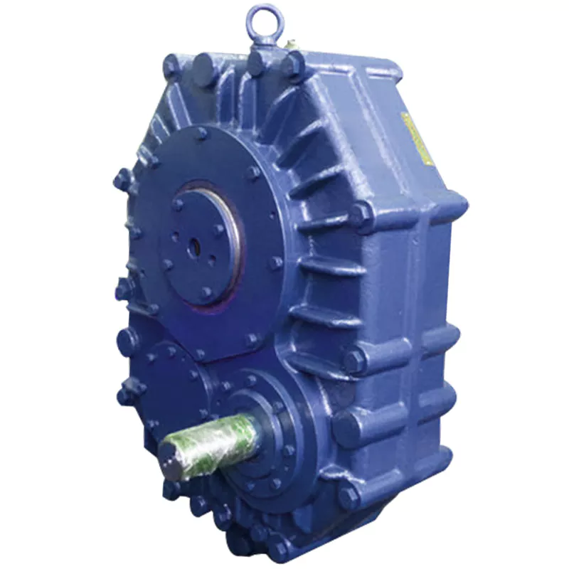
Are there any disadvantages or limitations to using gear reducer systems?
While gear reducer systems offer numerous advantages, they also come with certain disadvantages and limitations that should be considered during the selection and implementation process:
1. Size and Weight: Gear reducers can be bulky and heavy, especially for applications requiring high gear ratios. This can impact the overall size and weight of the machinery or equipment, which may be a concern in space-constrained environments.
2. Efficiency Loss: Despite their high efficiency, gear reducers can experience energy losses due to friction between gear teeth and other components. This can lead to a reduction in overall system efficiency, particularly in cases where multiple gear stages are used.
3. Cost: The design, manufacturing, and assembly of gear reducers can involve complex processes and precision machining, which can contribute to higher initial costs compared to other power transmission solutions.
4. Maintenance: Gear reducer systems require regular maintenance, including lubrication, inspection, and potential gear replacement over time. Maintenance activities can lead to downtime and associated costs in industrial settings.
5. Noise and Vibration: Gear reducers can generate noise and vibrations, especially at high speeds or when operating under heavy loads. Additional measures may be needed to mitigate noise and vibration issues.
6. Limited Gear Ratios: While gear reducers offer a wide range of gear ratios, there may be limitations in achieving extremely high or low ratios in certain designs.
7. Temperature Sensitivity: Extreme temperatures can affect the performance of gear reducer systems, particularly if inadequate lubrication or cooling is provided.
8. Shock Loads: While gear reducers are designed to handle shock loads to some extent, severe shock loads or abrupt changes in torque can still lead to potential damage or premature wear.
Despite these limitations, gear reducer systems remain widely used and versatile components in various industries, and their disadvantages can often be mitigated through proper design, selection, and maintenance practices.
How do gear reducers ensure efficient power transmission and motion control?
Gear reducers play a vital role in ensuring efficient power transmission and precise motion control in various industrial applications. They achieve this through the following mechanisms:
- 1. Speed Reduction/Increase: Gear reducers allow you to adjust the speed between the input and output shafts. Speed reduction is essential when the output speed needs to be lower than the input speed, while speed increase is used when the opposite is required.
- 2. Torque Amplification: By altering the gear ratio, gear reducers can amplify torque from the input to the output shaft. This enables machinery to handle higher loads and provide the necessary force for various tasks.
- 3. Gear Train Efficiency: Well-designed gear trains within reducers minimize power losses during transmission. Helical and spur gears, for example, offer high efficiency by distributing load and reducing friction.
- 4. Precision Motion Control: Gear reducers provide precise control over rotational motion. This is crucial in applications where accurate positioning, synchronization, or timing is required, such as in robotics, CNC machines, and conveyor systems.
- 5. Backlash Reduction: Some gear reducers are designed to minimize backlash, which is the play between gear teeth. This reduction in play ensures smoother operation, improved accuracy, and better control.
- 6. Load Distribution: Gear reducers distribute the load evenly among multiple gear teeth, reducing wear and extending the lifespan of the components.
- 7. Shock Absorption: In applications where sudden starts, stops, or changes in direction occur, gear reducers help absorb and dampen shocks, protecting the machinery and ensuring reliable operation.
- 8. Compact Design: Gear reducers provide a compact solution for achieving specific speed and torque requirements, allowing for space-saving integration into machinery.
By combining these principles, gear reducers facilitate the efficient and controlled transfer of power, enabling machinery to perform tasks accurately, reliably, and with the required force, making them essential components in a wide range of industries.

What industries and machinery commonly utilize gear reducers?
Gear reducers are widely used across various industries and types of machinery for torque reduction and speed control. Some common industries and applications include:
- 1. Manufacturing: Gear reducers are used in manufacturing equipment such as conveyors, mixers, and packaging machines to control speed and transmit power efficiently.
- 2. Automotive: They are utilized in vehicles for applications like power transmission in transmissions and differentials.
- 3. Aerospace: Gear reducers are used in aircraft systems, including landing gear mechanisms and engine accessories.
- 4. Robotics and Automation: They play a crucial role in robotic arms, CNC machines, and automated production lines.
- 5. Mining and Construction: Gear reducers are used in heavy machinery like excavators, bulldozers, and crushers for power transmission and torque multiplication.
- 6. Energy and Power Generation: Wind turbines, hydroelectric generators, and other power generation equipment use gear reducers to convert rotational speed and transmit power.
- 7. Marine and Shipbuilding: They are used in ship propulsion systems, steering mechanisms, and anchor handling equipment.
- 8. Material Handling: Gear reducers are essential in conveyor systems, elevators, and hoists for controlled movement of materials.
- 9. Food and Beverage: They find applications in food processing equipment like mixers, grinders, and packaging machines.
- 10. Paper and Pulp: Gear reducers are used in machinery for pulp processing, paper production, and printing.
These examples represent just a fraction of the industries and machinery that benefit from the use of gear reducers to optimize power transmission and achieve the desired motion characteristics.


editor by CX 2023-11-14
China supplier 25r/m 1.2KW 190BX RVE Series Collaborative Robot High Precision Cycloidal Gearbox For Agricultural Machinery gearbox and motor
Product Description
25r/m 1.2KW 190BX RVE Series Collaborative Robot High Precision Cycloidal Gearbox For Agricultural Machinery
Model:190BX-RVE
More Code And Specification:
| E series | C series | ||||
| Code | Outline dimension | General model | Code | Outline dimension | The original code |
| 120 | Φ122 | 6E | 10C | Φ145 | 150 |
| 150 | Φ145 | 20E | 27C | Φ181 | 180 |
| 190 | Φ190 | 40E | 50C | Φ222 | 220 |
| 220 | Φ222 | 80E | 100C | Φ250 | 250 |
| 250 | Φ244 | 110E | 200C | Φ345 | 350 |
| 280 | Φ280 | 160E | 320C | Φ440 | 440 |
| 320 | Φ325 | 320E | 500C | Φ520 | 520 |
| 370 | Φ370 | 450E | |||
Gear ratio And Specification
| E Series | C Series | ||
| Code | Reduction Ratio | New code | Monomer reduction ratio |
| 120 | 43,53.5,59,79,103 | 10CBX | 27.00 |
| 150 | 81,105,121,141,161 | 27CBX | 36.57 |
| 190 | 81,105,121,153 | 50CBX | 32.54 |
| 220 | 81,101,121,153 | 100CBX | 36.75 |
| 250 | 81,111,161,175.28 | 200CBX | 34.86 |
| 280 | 81,101,129,145,171 | 320CBX | 35.61 |
| 320 | 81,101,118.5,129,141,171,185 | 500CBX | 37.34 |
| 370 | 81,101,118.5,129,154.8,171,192.4 | ||
| Note 1: E series,such as by the shell(pin shell)output,the corresponding reduction ratio by 1 | |||
| Note 2: C series gear ratio refers to the motor installed in the casing of the reduction ratio,if installed on the output flange side,the corresponding reduction ratio by 1 | |||
Reducer type code
REV: main bearing built-in E type
RVC: hollow type
REA: with input flange E type
RCA: with input flange hollow type
Application:
Company Information
FAQ
Q: What’re your main products?
A: We currently produce Brushed Dc Motors, Brushed Dc Gear Motors, Planetary Dc Gear Motors, Brushless Dc Motors, Stepper motors, Ac Motors and High Precision Planetary Gear Box etc. You can check the specifications for above motors on our website and you can email us to recommend needed motors per your specification too.
Q: How to select a suitable motor?
A:If you have motor pictures or drawings to show us, or you have detailed specs like voltage, speed, torque, motor size, working mode of the motor, needed lifetime and noise level etc, please do not hesitate to let us know, then we can recommend suitable motor per your request accordingly.
Q: Do you have a customized service for your standard motors?
A: Yes, we can customize per your request for the voltage, speed, torque and shaft size/shape. If you need additional wires/cables soldered on the terminal or need to add connectors, or capacitors or EMC we can make it too.
Q: Do you have an individual design service for motors?
A: Yes, we would like to design motors individually for our customers, but it may need some mold developing cost and design charge.
Q: What’s your lead time?
A: Generally speaking, our regular standard product will need 15-30days, a bit longer for customized products. But we are very flexible on the lead time, it will depend on the specific orders.
Please contact us if you have detailed requests, thank you !
| Application: | Machinery, Robotic |
|---|---|
| Hardness: | Hardened Tooth Surface |
| Installation: | Vertical Type |
| Layout: | Coaxial |
| Gear Shape: | Cylindrical Gear |
| Step: | Double-Step |
| Customization: |
Available
| Customized Request |
|---|
Materials Used in Manufacturing Cycloidal Gearboxes
Cycloidal gearboxes are constructed using a variety of materials to ensure durability, strength, and efficient operation. Some common materials used include:
- Steel: Steel is a popular choice due to its high strength and durability. It can withstand heavy loads and provides excellent wear resistance, making it suitable for industrial applications.
- Aluminum: Aluminum is chosen for its lightweight properties and corrosion resistance. It’s often used in applications where weight is a concern, such as aerospace and robotics.
- Cast Iron: Cast iron offers good heat dissipation and is known for its high resistance to wear and shock. It’s commonly used in heavy-duty applications that require high torque and strength.
- Alloys: Various alloy combinations can be used to enhance specific properties such as corrosion resistance, heat resistance, and strength.
- Plastics and Composites: In some cases, plastic or composite materials may be used, particularly in applications where low noise, lightweight construction, and corrosion resistance are essential.
The material selection depends on factors like the application’s torque, speed, environmental conditions, and desired performance characteristics. Each material offers a unique set of advantages, allowing cycloidal gearboxes to be customized to meet diverse industrial needs.
History of Cycloidal Gear System Development
The history of cycloidal gear systems dates back to ancient times, with various forms of non-circular gears being used for specialized applications. The concept of the cycloidal gear system as we know it today, however, has evolved over centuries of engineering and innovation:
- Ancient Roots: The concept of using non-circular gears can be traced back to ancient civilizations, where devices like the “Antikythera Mechanism” (c. 150-100 BC) employed non-circular gear arrangements.
- Cam Mechanisms: During the Renaissance, engineers and inventors like Leonardo da Vinci explored mechanisms involving cams and followers, which are precursors to modern cycloidal gears.
- Cycloidal Motion Studies: In the 19th century, engineers and mathematicians like Franz Reuleaux and Robert Willis studied and developed mechanisms based on the principles of cycloidal motion.
- Early Cycloidal Gearboxes: The development of cycloidal gear systems gained momentum in the late 19th and early 20th centuries, with inventors like Emile Alluard and Louis André creating early forms of cycloidal gear mechanisms and gearboxes.
- Cycloidal Drive: The term “cycloidal drive” was coined by James Watt in the 18th century, referring to mechanisms that produce a motion resembling a rolling circle.
- Modern Cycloidal Gearboxes: The development of modern cycloidal gearboxes was further advanced by engineers like Ralph B. Heath, who patented the “Harmonic Drive” in the 1950s. This invention marked a significant step in the advancement and commercialization of precision cycloidal gear systems.
- Advancements and Applications: Over the decades, cycloidal gear systems have found applications in robotics, aerospace, automation, and other fields that require compactness, precision, and high torque capabilities.
The history of cycloidal gear system development reflects the contributions of many engineers and inventors who have refined and advanced the technology over time. Today, cycloidal gearboxes continue to play a crucial role in various industries and applications.
Disadvantages of Using a Cycloidal Gearbox
While cycloidal gearboxes offer various advantages, they also come with some disadvantages that should be considered:
- Lower Efficiency at High Speeds: Cycloidal gearboxes can experience a decrease in efficiency at high speeds due to increased friction and rolling resistance.
- Complex Design: The internal arrangement of pins, lobes, and bearings can result in a relatively complex design, which may lead to higher manufacturing costs and maintenance challenges.
- Limited Gear Ratio Range: Cycloidal gearboxes might have limitations in terms of achieving very high gear ratios, which can impact their suitability for certain applications.
- Cost: The specialized design and precision manufacturing involved in producing cycloidal gearboxes can lead to higher upfront costs compared to other gearbox types.
- Noise Generation: While generally quieter than some other types of gearboxes, cycloidal gearboxes can still produce noise during operation, which might need to be addressed in noise-sensitive applications.
- Availability: Cycloidal gearboxes might not be as widely available as other gearbox types, potentially leading to longer lead times for procurement and replacement parts.
- Limited Backlash Adjustability: While cycloidal gearboxes have minimal backlash, adjusting or fine-tuning the backlash might be more challenging compared to other gearbox types.
Despite these disadvantages, cycloidal gearboxes remain a valuable choice for specific applications where their unique advantages outweigh the drawbacks.


editor by CX 2023-10-26
China Good quality Agricultural Machinery Conical – Cylindrical Gear CZPT Worm Gearbox Reducer supplier
Product Description
GRH specialized in providing hydraulic components and solutions for hydraulic systems.
With continuous improvement and enthusiasm over the past 30 years, CHINAMFG has developed into an emerging power in the fluid power industry since it was established in 1986.
GRH (ZheJiang ) – International Sales Office
GRH (ZheJiang ) – Manufacturing Facility and Domestic Sales Office
—————————————————————————————————————————————————
Production description
| We can produce motor according to your needs ! |
About Us
Application and Partners
Contact us!
| Application: | Motor, Machinery, Agricultural Machinery |
|---|---|
| Hardness: | Hardened Tooth Surface |
| Installation: | Vertical Type |
| Layout: | Expansion |
| Gear Shape: | Conical – Cylindrical Gear |
| Step: | Stepless |
| Samples: |
US$ 1050/Piece
1 Piece(Min.Order) | |
|---|
| Customization: |
Available
| Customized Request |
|---|
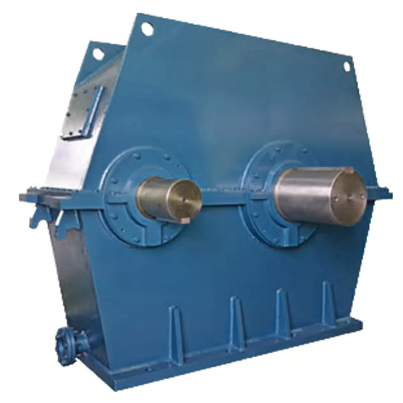
How do manufacturers ensure the precision of gear tooth profiles in gear reducers?
Manufacturers employ several techniques to ensure the precision of gear tooth profiles in gear reducers, which is crucial for optimal performance and efficiency:
1. Precision Machining: Gear teeth are typically machined using advanced CNC (Computer Numerical Control) machines that can achieve high levels of accuracy and repeatability. This ensures consistent gear tooth profiles across multiple components.
2. Quality Control Measures: Rigorous quality control processes, such as dimensional inspections and profile measurements, are performed at various stages of manufacturing to verify that gear tooth profiles meet the required specifications.
3. Tooth Profile Design: Engineers use specialized software and simulation tools to design gear tooth profiles with precise involute shapes and accurate dimensions. These designs are then translated into machine instructions for manufacturing.
4. Material Selection: High-quality materials with excellent wear resistance and dimensional stability are chosen to minimize the potential for deformation or inaccuracies during machining and operation.
5. Heat Treatment: Heat treatment processes, such as carburizing and quenching, are applied to enhance the surface hardness and durability of gear teeth, reducing the risk of wear and deformation over time.
6. Tooth Grinding and Finishing: After initial machining, gear teeth often undergo precision grinding and finishing processes to achieve the desired tooth profile accuracy and surface finish.
7. Post-Processing Inspection: Gear tooth profiles are inspected again after manufacturing processes to verify that the final components meet the specified tolerances and performance criteria.
8. Computer-Aided Manufacturing (CAM): CAM software is used to generate tool paths and machining instructions, enabling precise control over tool movements and material removal during gear manufacturing.
By combining these techniques and leveraging advanced manufacturing technologies, manufacturers can achieve the necessary precision in gear tooth profiles, resulting in reliable and efficient gear reducers for various industrial applications.
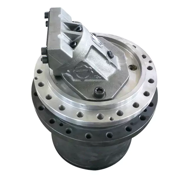
What factors should be considered when selecting the right gear reducer?
Choosing the appropriate gear reducer involves considering several crucial factors to ensure optimal performance and efficiency for your specific application:
- 1. Torque and Power Requirements: Determine the amount of torque and power your machinery needs for its operation.
- 2. Speed Ratio: Calculate the required speed reduction or increase to match the input and output speeds.
- 3. Gear Type: Select the appropriate gear type (helical, bevel, worm, planetary, etc.) based on your application’s torque, precision, and efficiency requirements.
- 4. Mounting Options: Consider the available space and the mounting configuration that suits your machinery.
- 5. Environmental Conditions: Evaluate factors such as temperature, humidity, dust, and corrosive elements that may impact the gear reducer’s performance.
- 6. Efficiency: Assess the gear reducer’s efficiency to minimize power losses and improve overall system performance.
- 7. Backlash: Consider the acceptable level of backlash or play between gear teeth, which can affect precision.
- 8. Maintenance Requirements: Determine the maintenance intervals and procedures necessary for reliable operation.
- 9. Noise and Vibration: Evaluate noise and vibration levels to ensure they meet your machinery’s requirements.
- 10. Cost: Compare the initial cost and long-term value of different gear reducer options.
By carefully assessing these factors and consulting with gear reducer manufacturers, engineers and industry professionals can make informed decisions to select the right gear reducer for their specific application, optimizing performance, longevity, and cost-effectiveness.
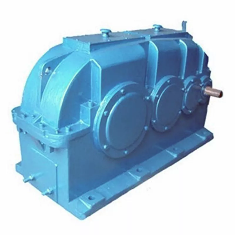
How do gear reducers contribute to speed reduction and torque increase?
Gear reducers play a crucial role in mechanical systems by achieving speed reduction and torque increase through the principle of gear ratios. Here’s how they work:
Gear reducers consist of multiple gears with different sizes, known as gear pairs. These gears are meshed together, and their teeth interlock to transmit motion and power. The gear ratio is determined by the ratio of the number of teeth on the input gear (driver) to the number of teeth on the output gear (driven).
Speed Reduction: When a larger gear (output gear) is driven by a smaller gear (input gear), the output gear rotates at a slower speed than the input gear. This reduction in speed is proportional to the gear ratio. As a result, gear reducers are used to slow down the rotational speed of the output shaft compared to the input shaft.
Torque Increase: The interlocking teeth of gears create a mechanical advantage that allows gear reducers to increase torque output. When the input gear applies a force (torque) to the teeth, it is transmitted to the output gear with greater force due to the leverage provided by the larger diameter of the output gear. The torque increase is inversely proportional to the gear ratio and is essential for applications requiring high torque at lower speeds.
By selecting appropriate gear ratios and arranging gear pairs, gear reducers can achieve various speed reduction and torque multiplication factors, making them essential components in machinery and equipment where precise control of speed and torque is necessary.


editor by CX 2023-10-25
China high quality Bld Horizontal Cycloidal Pin-Wheel Gear Reducer Planetary for Construction Machinery Industry gearbox definition
Product Description
Product Description
Product Features
– Highly Standard Modular Designed
– Quality material ensures the product reliability
– High Strength,Compact Dimension
– Long Service Life
– Low Noise
– High Efficiency
– Large radial loading ability
– Cost-effective
Detailed Photos
Product Parameters
|
Models |
Power |
Ratio |
Max. Torque |
Output Shaft Dia. |
Input Shaft Dia. |
|
1 Stage |
|||||
|
X2(B0/B12) |
0.37~1.5 |
9~87 |
150 |
Φ25(Φ30) |
Φ15 |
|
X3(B1/B15) |
0.55~2.2 |
9~87 |
250 |
Φ35 |
Φ18 |
|
X4(B2/B18) |
0.75~4.0 |
9~87 |
500 |
Φ45 |
Φ22 |
|
X5(B3/B22) |
1.5~7.5 |
9~87 |
1,000 |
Φ55 |
Φ30 |
|
X6(B4/B27) |
2.2~11 |
9~87 |
2,000 |
Φ65(Φ70) |
Φ35 |
|
X7 |
3.0~11 |
9~87 |
2,700 |
Φ80 |
Φ40 |
|
X8(B5/B33) |
5.5~18.5 |
9~87 |
4,500 |
Φ90 |
Φ45 |
|
X9(B6/B39) |
7.5~30 |
9~87 |
7,100 |
Φ100 |
Φ50 |
|
X10(B7/B45) |
15~45 |
9~87 |
12,000 |
Φ110 |
Φ55 |
|
X11(B8/B55) |
18.5~55 |
9~87 |
20,000 |
Φ130 |
Φ70 |
Our Advantages
Packaging & Shipping
Company Profile
Xihu (West Lake) Dis.ng Transmission Equipment Co., Ltd. located HangZhou city, ZHangZhoug, as 1 professional
manufacturer and exporter of cycloidal pin wheel reducer,worm reducer, gear reducer, gearbox ,
AC motor and relative spare parts, owns rich experience in this line for many years.
We are 1 direct factory, with advanced production equipment, the strong development team and
producing capacity to offer quality products for customers.
Our products widely served to various industries of Metallurgy, Chemicals, textile,medicine,wooden
etc. Main markets: China, Africa,Australia,Vietnam, Turkey,Japan, Korea, Philippines…
Welcome to ask us any questions, good offer always for you for long term business.
FAQ
Q: Are you trading company or manufacturer?
A: We are factory.
Q: How long is your delivery time?
A: Generally it is 5-10 days if the goods are in stock. or it is 15-20 days if the goods are not in stock.
Q: Can we buy 1 pc of each item for quality testing?
A: Yes, we are glad to accept trial order for quality testing.
Q:How to choose a gearbox which meets your requirement?
A:You can refer to our catalogue to choose the gearbox or we can help to choose when you provide
the technical information of required output torque, output speed and motor parameter etc.
Q: What information shall we give before placing a purchase order?
A:a) Type of the gearbox, ratio, input and output type, input flange, mounting position, and motor informationetc.
b) Housing color.
c) Purchase quantity.
d) Other special requirements.
| Application: | Motor, Machinery, Marine, Agricultural Machinery |
|---|---|
| Function: | Change Drive Direction, Speed Changing, Speed Reduction |
| Layout: | Cycloidal |
| Hardness: | Hardened Tooth Surface |
| Installation: | Horizontal Type |
| Step: | Four-Step |
| Samples: |
US$ 200/Piece
1 Piece(Min.Order) | |
|---|
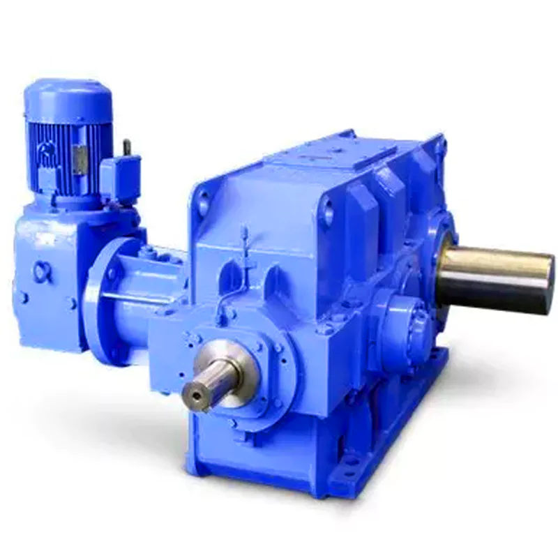
What are the considerations for choosing the appropriate lubrication for gear reducers?
Choosing the appropriate lubrication for gear reducers is crucial for ensuring optimal performance, longevity, and efficiency. Several considerations should be taken into account when selecting the right lubrication:
1. Load and Torque: The magnitude of the load and torque transmitted by the gear reducer affects the lubrication’s viscosity and film strength requirements. Heavier loads may necessitate higher viscosity lubricants.
2. Operating Speed: The speed at which the gear reducer operates impacts the lubrication’s ability to maintain a consistent and protective film between gear surfaces.
3. Temperature Range: Consider the temperature range of the operating environment. Lubricants with suitable viscosity indexes are crucial to maintaining performance under varying temperature conditions.
4. Contaminant Exposure: If the gear reducer is exposed to dust, dirt, water, or other contaminants, the lubrication should have proper sealing properties and resistance to contamination.
5. Lubrication Interval: Determine the desired maintenance interval. Some lubricants require more frequent replacement, while others offer extended operational periods.
6. Compatibility with Materials: Ensure that the chosen lubricant is compatible with the materials used in the gear reducer, including gears, bearings, and seals.
7. Noise and Vibration: Some lubricants have properties that can help reduce noise and dampen vibrations, improving the overall user experience.
8. Environmental Impact: Consider environmental regulations and sustainability goals when selecting lubricants.
9. Manufacturer Recommendations: Follow the manufacturer’s recommendations and guidelines for lubrication type, viscosity grade, and maintenance intervals.
10. Monitoring and Analysis: Implement a lubrication monitoring and analysis program to assess lubricant condition and performance over time.
By carefully evaluating these considerations and consulting with lubrication experts, industries can choose the most suitable lubrication for their gear reducers, ensuring reliable and efficient operation.

Can gear reducers be used for both speed reduction and speed increase?
Yes, gear reducers can be utilized for both speed reduction and speed increase, depending on their design and arrangement. The functionality to either decrease or increase rotational speed is achieved by altering the arrangement of gears within the gearbox.
1. Speed Reduction: In speed reduction applications, a gear reducer is designed with gears of different sizes. The input shaft connects to a larger gear, while the output shaft is connected to a smaller gear. As the input shaft rotates, the larger gear turns the smaller gear, resulting in a decrease in output speed compared to the input speed. This configuration provides higher torque output at a lower speed, making it suitable for applications that require increased force or torque.
2. Speed Increase: For speed increase, the gear arrangement is reversed. The input shaft connects to a smaller gear, while the output shaft is connected to a larger gear. As the input shaft rotates, the smaller gear drives the larger gear, resulting in an increase in output speed compared to the input speed. However, the torque output is lower than that of speed reduction configurations.
By choosing the appropriate gear ratios and arrangement, gear reducers can be customized to meet specific speed and torque requirements for various industrial applications. It’s important to select the right type of gear reducer and configure it correctly to achieve the desired speed reduction or speed increase.

How do gear reducers handle variations in input and output speeds?
Gear reducers are designed to handle variations in input and output speeds through the use of different gear ratios and configurations. They achieve this by utilizing intermeshing gears of varying sizes to transmit torque and control rotational speed.
The basic principle involves connecting two or more gears with different numbers of teeth. When a larger gear (driving gear) engages with a smaller gear (driven gear), the rotational speed of the driven gear decreases while the torque increases. This reduction in speed and increase in torque enable gear reducers to efficiently adapt to variations in input and output speeds.
The gear ratio is a critical factor in determining how much the speed and torque change. It is calculated by dividing the number of teeth on the driven gear by the number of teeth on the driving gear. A higher gear ratio results in a greater reduction in speed and a proportionate increase in torque.
Planetary gear reducers, a common type, use a combination of gears including sun gears, planet gears, and ring gears to achieve different speed reductions and torque enhancements. This design provides versatility in handling variations in speed and torque requirements.
In summary, gear reducers handle variations in input and output speeds by using specific gear ratios and gear arrangements that enable them to efficiently transmit power and control motion characteristics according to the application’s needs.


editor by CX 2023-09-11
China best Rotary Reducer Machinery Repair Shops Cycloidal Gear Reducer differential gearbox
Product Description
GRH specialized in providing hydraulic components and solutions for hydraulic systems.
With continuous improvement and enthusiasm over the past 30 years, CZPT has developed into an emerging power in the fluid power industry since it was established in 1986.
GRH (ZheJiang ) – International Sales Office
GRH (ZheJiang ) – Manufacturing Facility and Domestic Sales Office
—————————————————————————————————————————————————
Production description
| We can produce motor according to your needs ! |
About Us
Application and Partners
Contact us!
| Application: | Motor, Machinery, Agricultural Machinery |
|---|---|
| Hardness: | Hardened Tooth Surface |
| Installation: | Vertical Type |
| Layout: | Expansion |
| Gear Shape: | Conical – Cylindrical Gear |
| Step: | Stepless |
| Samples: |
US$ 1050/Piece
1 Piece(Min.Order) | |
|---|
| Customization: |
Available
| Customized Request |
|---|

What are the considerations for choosing the appropriate lubrication for gear reducers?
Choosing the appropriate lubrication for gear reducers is crucial for ensuring optimal performance, longevity, and efficiency. Several considerations should be taken into account when selecting the right lubrication:
1. Load and Torque: The magnitude of the load and torque transmitted by the gear reducer affects the lubrication’s viscosity and film strength requirements. Heavier loads may necessitate higher viscosity lubricants.
2. Operating Speed: The speed at which the gear reducer operates impacts the lubrication’s ability to maintain a consistent and protective film between gear surfaces.
3. Temperature Range: Consider the temperature range of the operating environment. Lubricants with suitable viscosity indexes are crucial to maintaining performance under varying temperature conditions.
4. Contaminant Exposure: If the gear reducer is exposed to dust, dirt, water, or other contaminants, the lubrication should have proper sealing properties and resistance to contamination.
5. Lubrication Interval: Determine the desired maintenance interval. Some lubricants require more frequent replacement, while others offer extended operational periods.
6. Compatibility with Materials: Ensure that the chosen lubricant is compatible with the materials used in the gear reducer, including gears, bearings, and seals.
7. Noise and Vibration: Some lubricants have properties that can help reduce noise and dampen vibrations, improving the overall user experience.
8. Environmental Impact: Consider environmental regulations and sustainability goals when selecting lubricants.
9. Manufacturer Recommendations: Follow the manufacturer’s recommendations and guidelines for lubrication type, viscosity grade, and maintenance intervals.
10. Monitoring and Analysis: Implement a lubrication monitoring and analysis program to assess lubricant condition and performance over time.
By carefully evaluating these considerations and consulting with lubrication experts, industries can choose the most suitable lubrication for their gear reducers, ensuring reliable and efficient operation.

What maintenance practices are essential for prolonging the lifespan of gear reducers?
Proper maintenance is crucial for extending the lifespan and ensuring optimal performance of gear reducers. Here are essential maintenance practices:
- 1. Lubrication: Regular lubrication of gear reducers is vital to reduce friction, wear, and heat generation. Use the recommended lubricant and follow the manufacturer’s guidelines for lubrication intervals.
- 2. Inspection: Routinely inspect gear reducers for signs of wear, damage, or leaks. Check for unusual noises, vibrations, or temperature increases during operation.
- 3. Alignment: Ensure proper alignment of the input and output shafts. Misalignment can lead to increased wear, noise, and reduced efficiency. Align the components according to the manufacturer’s specifications.
- 4. Cooling and Ventilation: Maintain proper cooling and ventilation to prevent overheating. Ensure that cooling fans and vents are clean and unobstructed.
- 5. Seal Maintenance: Inspect and replace seals as needed to prevent contaminants from entering the gear reducer. Contaminants can lead to accelerated wear and reduced performance.
- 6. Bolts and Fasteners: Regularly check and tighten bolts and fasteners to prevent loosening during operation, which can cause misalignment or component damage.
- 7. Replacing Worn Components: Replace worn or damaged components, such as gears, bearings, and seals, with genuine parts from the manufacturer.
- 8. Vibration Analysis: Conduct periodic vibration analysis to identify potential issues early. Excessive vibration can indicate misalignment or component wear.
- 9. Maintenance Records: Keep detailed maintenance records, including lubrication schedules, inspection dates, and component replacements. This helps track the history of the gear reducer and aids in future maintenance planning.
- 10. Training: Provide proper training to maintenance personnel on gear reducer maintenance and troubleshooting techniques.
By adhering to these maintenance practices, you can maximize the lifespan of your gear reducers, minimize downtime, and ensure reliable operation in your industrial processes.

What are the benefits of using a gear reducer in industrial applications?
Gear reducers offer several benefits that make them indispensable in various industrial applications:
1. Speed Reduction: Gear reducers allow the reduction of high-speed input from motors or engines to lower, more usable output speeds for specific applications, ensuring proper equipment operation and safety.
2. Torque Increase: By leveraging the mechanical advantage of gear ratios, gear reducers can significantly increase torque output, enabling the handling of heavy loads and providing the necessary power for tasks such as lifting, conveying, and processing.
3. Precise Control: Gear reducers enable fine-tuning of rotational speed and torque, providing precise control over machinery and processes, which is crucial in industries like manufacturing, material handling, and robotics.
4. Shock Load Absorption: Gear reducers can absorb and dampen sudden shocks or changes in load, protecting both the machinery and connected components from abrupt forces that could otherwise lead to damage.
5. Versatility: With various gear types (e.g., spur, helical, worm) and designs, gear reducers can be tailored to different applications, including those requiring specific speed ratios, torque ranges, and environmental conditions.
6. Efficient Power Transmission: Gear reducers offer high mechanical efficiency, minimizing energy loss during power transmission, which is especially valuable in energy-conscious industries.
7. Compact Design: Gear reducers provide a compact solution for transmitting power and adjusting speeds, making them suitable for installations with space constraints.
8. Reliability and Longevity: Well-designed and properly maintained gear reducers can offer extended service life, contributing to reduced downtime and maintenance costs.
Overall, gear reducers enhance the performance, efficiency, and reliability of industrial equipment, making them essential components in a wide range of applications across various industries.


editor by CX 2023-09-07
China Custom Wb65 Series Gear Speed Reducer Cycloidal Gearbox with AC Motor for Metallurgical Machinery with high quality
Product Description
Product Description
WB65 series Gear Speed Reducer cycloidal gearbox With AC Motor for Metallurgical Machinery
Components:
1. Housing: Cast Iron
2. Gearset: Cycloid Wheel & Pin Wheel
3. Input Configurations:
Equipped with Electric Motors (3 Phase AC Motor, Single Phase AC Motor, Brake Motor, Servo Motor)
IEC-normalized Motor Flange
Keyed CZPT Shaft Input
4. Output Configurations:
Keyed CZPT Shaft Output
Detailed Photos
Features:
1. WB series cycloidal reducers have the same features and characteristics with X & B series cycloidal reducers. The differences are WB series cycloidal reducers have smaller sizes and power
2. Grease lubrication, oil leak is not possible
3. Multiple mounting options
Product Parameters
| Models | Power | Ratio | Max. Torque | Output Shaft Dia. | Input Shaft Dia. |
| 1 Stage | |||||
| WB65 | 0.04~0.12 | 9~87 | 25 | Φ12 | Φ10 |
| WB85 | 0.09~0.37 | 9~87 | 60 | Φ14 | Φ12 |
| WB100 | 0.18~0.75 | 9~87 | 120 | Φ18 | Φ14 |
| WB120 | 0.37~1.5 | 9~87 | 180 | Φ30 | Φ15 |
| WB150 | 0.55~3.0 | 9~87 | 250 | Φ35 | Φ20 |
| 2 Stage | |||||
| WBE1065 | 0.04~0.12 | 121~1849 | 120 | Φ18 | Φ10 |
| WBE1285 | 0.09~0.37 | 121~1849 | 180 | Φ30 | Φ12 |
| WBE1510 | 0.18~0.75 | 121~1849 | 250 | Φ35 | Φ14 |
1 Stage Ratio: 9, 11, 17, 23, 29, 35, 43, 59, 71, 87
2 Stage Ratio: 121, 187, 289, 385, 473, 595, 731, 989, 1225, 1849
Installation:
Foot Mounted
Flange Mounted
Lubrication:
Grease Lubrication
Cooling:
Natural Cooling
Packaging & Shipping
Company Profile
After Sales Service
| Pre-sale services | 1. Select equipment model. |
| 2.Design and manufacture products according to clients’ special requirement. | |
| 3.Train technical personal for clients | |
| Services during selling | 1.Pre-check and accept products ahead of delivery. |
| 2. Help clients to draft solving plans. | |
| After-sale services | 1.Assist clients to prepare for the first construction scheme. |
| 2. Train the first-line operators. | |
| 3.Take initiative to eliminate the trouble rapidly. | |
| 4. Provide technical exchanging. |
FAQ
Our Services:FAQ:
1.Q:What kinds of gearbox can you produce for us?
A:Main products of our company: UDL series speed variator,RV series worm gear reducer, ATA series shaft mounted gearbox, X,B series gear reducer,
P series planetary gearbox and R, S, K, and F series helical-tooth reducer, more
than 1 hundred models and thousands of specifications
2.Q:Can you make as per custom drawing?
A: Yes, we offer customized service for customers.
3.Q:What is your terms of payment ?
A: 30% Advance payment by T/T after signing the contract.70% before delivery
4.Q:What is your MOQ?
A: 1 Set
If you have any demand for our products please feel free to contact me.
| Application: | Motor, Machinery, Industry |
|---|---|
| Function: | Speed Changing, Speed Reduction |
| Layout: | Cycloidal |
| Hardness: | Hardened Tooth Surface |
| Installation: | Vertical Type |
| Step: | Stepless |
| Customization: |
Available
| Customized Request |
|---|
What is a Cycloidal Gearbox?
A cycloidal gearbox, also known as a cycloidal drive, is a type of gearing mechanism that utilizes the principle of cycloidal motion for power transmission. It consists of several components, including a high-speed input shaft, a set of cycloidal pins or rollers, and an outer stationary ring with lobed profiles.
The operation of a cycloidal gearbox involves a unique mechanism:
- Input Shaft: The high-speed input shaft is connected to the driving source, such as an electric motor. It transfers rotational motion to the cycloidal pins.
- Cycloidal Pins or Rollers: These pins or rollers are typically arranged around the input shaft in a circular pattern. As the input shaft rotates, the cycloidal pins also rotate, causing them to engage with the lobes on the outer stationary ring.
- Outer Stationary Ring: The outer ring has lobed profiles, and it remains stationary during operation. The lobes of the outer ring interact with the cycloidal pins or rollers, causing them to move in a
Assembling and Disassembling a Cycloidal Gearbox
Assembling and disassembling a cycloidal gearbox requires careful attention to detail and precision. The process can vary depending on the specific design of the gearbox, but the general steps involve:
- Preparation: Gather all the necessary tools, components, and safety equipment for the assembly or disassembly process. Ensure a clean and organized workspace.
- Disassembly: To disassemble a cycloidal gearbox, follow these steps:
- Remove any external components or covers to access the gearbox internals.
- Identify and mark the positions of all components for reassembly.
- Release any locking mechanisms or fasteners that hold the gearbox components together.
- Remove each component carefully, starting from the outermost layers and moving inward.
- Cleaning and Inspection: Clean all components thoroughly using appropriate cleaning agents. Inspect each part for wear, damage, or any signs of degradat
Efficiency of Cycloidal Gearboxes in Power Transmission
Cycloidal gearboxes offer relatively high power transmission efficiency compared to other types of gearboxes. The efficiency of a cycloidal gearbox depends on various factors, including the design, quality of components, lubrication, and load conditions.
Typically, the power transmission efficiency of a cycloidal gearbox ranges from 85% to 95%. However, this can vary based on several factors:
- Number of Reduction Stages: Multi-stage cycloidal gearboxes may experience slightly lower efficiency due to multiple gear meshing interactions.
- Quality and Design: Well-designed and precision-manufactured cycloidal gearboxes tend to exhibit higher efficiency.
- Lubrication: Proper lubrication is crucial for reducing friction and enhancing efficiency. Insufficient or deteriorated lubrication can lead to efficiency losses.
- Load Conditions: Higher loads and torque levels can lead to higher friction and lower efficiency. Properly matching the gearbox to the application is essential.
Despite minor efficiency losses compared to some other gearbox types, the benefits of compactness, high torque density, and precise motion control often outweigh the efficiency considerations in many applications.
ion. Replace any components that are worn out or damaged.
- Reassembly: To assemble the cycloidal gearbox, follow these steps:
- Begin by assembling the internal components in the reverse order of disassembly.
- Apply lubrication to the gears and other moving parts as recommended by the manufacturer.
- Follow the markings made during disassembly to ensure correct positioning and alignment of components.
- Gradually secure each component with the appropriate fasteners, ensuring proper torque settings.
- Reattach any external covers or components that were removed earlier.
- Testing: After reassembly, perform functional tests to ensure that the gearbox operates smoothly and without any issues. Check for any abnormal noises, vibrations, or irregular movements.
- Final Checks: Double-check all fasteners, connections, and alignments. Verify that the gearbox functions as intended and meets performance specifications.
- Documentation: Keep detailed records of the assembly process, including torque settings, markings, and any adjustments made during reassembly. This documentation will be useful for future maintenance or repairs.
It’s important to note that cycloidal gearboxes can have complex designs, and the exact procedure for assembly and disassembly may vary. Always refer to the manufacturer’s documentation and guidelines for specific instructions related to your gearbox model.
unique motion known as epicycloidal or hypocycloidal motion.
The interaction between the cycloidal pins and the lobed profiles of the outer ring results in smooth and controlled motion transmission. The mechanism provides advantages such as high torque capacity, compact size, and precise positioning capabilities.
Cycloidal gearboxes are widely used in various applications, including robotics, automation, packaging machinery, and other industrial systems where high torque, precision, and compact design are essential.


editor by CX 2023-08-31
China Standard Factory Wholesale Backlash Less Than 1 Arc. Min Heavy Duty Gearbox for Textile Machinery manufacturer
Product Description
Product Description
Factory wholesale Backlash less than 1 arc.min heavy duty gearbox for Textile Machinery
high-precision corner reducer for 5 axis machining center developed and manufactured by WEITENSTAN together with German and ZheJiang technicians for many years.
This high-precision corner reducer has high precision (backlash less than 1arcmin), low noise (68dB), and can replace the harmonic drive reducer. The life and rigidity are 3 times longer than the harmonic.
high-precision corner reducer has the characteristics of smaller, ultra-thin, lightweight and high rigidity, anti-overload and high torque. With good deceleration performance, smooth operation and accurate positioning can be achieved. Integrated design, can be directly connected with the motor, to achieve high precision, high rigidity, high durability and other advantages. It is designed for high speed ratio, high geometric accuracy, low motion loss, large torque capacity and high stiffness applications. The compact design (minimum OD ≈40mm, currently the world’s smallest precision cycloidal pin-wheel reducer) allows it to be installed in limited Spaces.
Reducer drawings
Detailed Photos
Product Advantage
Factory wholesale Backlash less than 1 arc.min heavy duty gearbox for Textile Machinery
advantages:
1, fine precision cycloidal structure
Ultra flat shape is achieved through differential reduction mechanism and thin cross roller bearing, contributing to the compact size of the equipment. The combination of small size and unmatched superior parameters achieves the best combination of performance, price and size (high cost performance).
2. Excellent accuracy (transmission loss ≤1 arcmin)
Through the complex meshing of precision cycloid gear and high precision roller pin, higher transmission accuracy is achieved while maintaining small size and high speed ratio.
3, high rigidity
Increase the mesh rate to disperse the load, so the rigidity is high.
4. High overload capacity
It maintains trouble-free operation under abnormally low noise and vibration conditions while ensuring excellent overturning and torsional stiffness parameters. Integrated axial radial cross roller bearings, high load capacity and overload capacity of the reducer, can ensure users to provide a variety of temperature range of applications.
5, the motor installation is simple
Electromechanical integration design, can be directly connected with the motor, any brand of motor can be installed directly, without adding any device.
6. Maintenance free
Seal grease to achieve maintenance free. No refueling, no mounting direction restrictions.
7, stable performance
The manufacturing process of high wear-resistant materials and high precision parts has been certified by ISO9000 quality system, which guarantees the reliable operation of the reducer.
Product Classification
WF Series
High Precision Miniature Reducer
WF series is a high precision micro cycloidal reducer with flange, which has a wide range of applications. This series of reducers includes precise reduction mechanisms and radial – axial roller bearings. The unique design allows load to act directly on the output flange or housing without additional bearings. WF series reducer is characterized by module design, can be installed through the flange motor and reducer, belongs to the motor directly connected reducer.
WFH Series
High Precision Miniature Reducer
WFH series is a hollow form of high precision miniature cycloidal reducer, wire, compressed air pipeline, drive shaft can be through the hollow shaft, non-motor direct connection type reducer. The WFH series is fully sealed, full of grease and includes precise deceleration mechanism and radial – axial roller bearings. The unique design allows load to be acted directly on the output flange or housing without additional bearings.
WR Series
high-precision corner reducer
The WR series is a flange output corner reducer. Like the WF and WFH series, it is a high-precision reducer (backlash less than 1 arc.min), and the level 2 can also be within 1 arc.min, which is higher than other types. Corner type reducer. It can replace the harmonic drive reducer, and its life and rigidity are more than 3 times that of the harmonic.
Product Parameters
| Size | reduction ratio | Rated output moment | Allowable torque of start and stop | Instantaneous allowable moment | Rated input speed | Maximum input speed | Tilt stiffness | Torsional stiffness | No-load starting torque | Transmission accuracy | Error accuracy | Moment of inertia | Weight | |
| Axis rotation | Shell rotation | Nm | Nm | Nm | rpm | rpm | Nm/arcmin | Nm/arcmin | Nm | arcmin | arcmin | kg-m² | kg | |
| WR25 | 21 | 20 | 110 | 220 | 330 | 3000 | 5500 | 131 | 24 | 0.47 | P1≤±1 P2≤±3 | P1≤±1 P2≤±3 | 6.12 | 2 |
| 31 | 30 | 0.41 | 5.67 | |||||||||||
| 41 | 40 | 0.38 | 4.9 | |||||||||||
| 51 | 50 | 0.35 | 4.56 | |||||||||||
| 81 | 80 | 0.31 | 4.25 | |||||||||||
| WR32 | 25 | 24 | 190 | 380 | 570 | 3000 | 4500 | 240 | 35 | 1.15 | P1≤±1 P2≤±3 | P1≤±1 P2≤±3 | 11 | 4.2 |
| 31 | 30 | 1.1 | 10.8 | |||||||||||
| 51 | 50 | 0.77 | 9.35 | |||||||||||
| 81 | 80 | 0.74 | 8.32 | |||||||||||
| 101 | 100 | 0.6 | 7.7 | |||||||||||
| WR40 | 25 | 24 | 320 | 640 | 960 | 3000 | 4000 | 377 | 50 | 1.35 | P1≤±1 P2≤±3 | P1≤±1 P2≤±3 | 13.2 | 6.6 |
| 31 | 30 | 1.32 | 12.96 | |||||||||||
| 51 | 50 | 0.92 | 11.22 | |||||||||||
| 81 | 80 | 0.81 | 9.84 | |||||||||||
| 121 | 120 | 0.72 | 8.4 | |||||||||||
Installation Instructions
Company Profile
Q: Speed reducer grease replacement time
A: When sealing appropriate amount of grease and running reducer, the standard replacement time is 20000 hours according to the aging condition of the grease. In addition, when the grease is stained or used in the surrounding temperature condition (above 40ºC), please check the aging and fouling of the grease, and specify the replacement time.
Q: Delivery time
A: Fubao has 2000+ production base, daily output of 1000+ units, standard models within 7 days of delivery.
Q: Reducer selection
A: Fubao provides professional product selection guidance, with higher product matching degree, higher cost performance and higher utilization rate.
Q: Application range of reducer
A: Fubao has a professional research and development team, complete category design, can match any stepping motor, servo motor, more accurate matching.
|
Shipping Cost:
Estimated freight per unit. |
To be negotiated |
|---|
| Application: | Motor, Machinery, Agricultural Machinery, Humanoid Robot |
|---|---|
| Hardness: | Hardened Tooth Surface |
| Installation: | Vertical Type |
| Customization: |
Available
| Customized Request |
|---|

The Advantages of Using a Cyclone Gearbox
Using a cycloidal gearbox to drive an input shaft is a very effective way to reduce the speed of a machine. It does this by reducing the speed of the input shaft by a predetermined ratio. It is capable of very high ratios in relatively small sizes.
Transmission ratio
Whether you’re building a marine propulsion system or a pump for the oil and gas industry, there are certain advantages to using cycloidal gearboxes. Compared to other gearbox types, they’re shorter and have better torque density. These gearboxes also offer the best weight and positioning accuracy.
The basic design of a cycloidal gearbox is similar to that of a planetary gearbox. The main difference is in the profile of the gear teeth.
Cycloid gears have less tooth flank wear and lower Hertzian contact stress. They also have lower friction and torsional stiffness. These advantages make them ideal for applications that involve heavy loads or high-speed drives. They’re also good for high gear ratios.
In a cycloidal gearbox, the input shaft drives an eccentric bearing, while the output shaft drives the cycloidal disc. The cycloidal disc rotates around a fixed ring, and the pins of the ring gear engage the holes in the disc. The pins then drive the output shaft as the disc rotates.
Cycloid gears are ideal for applications that require high gear ratios and low friction. They’re also good for applications that require high torsional stiffness and shock load resistance. They’re also suitable for applications that require a compact design and low backlash.
The transmission ratio of a cycloidal gearbox is determined by the number of lobes on the cycloidal disc. The n=n design of the cycloidal disc moves one lobe per revolution of the input shaft.
Cycloid gears can be manufactured to reduce the gear ratio from 30:1 to 300:1. These gears are suitable for high-end applications, especially in the automation industry. They also offer the best positioning accuracy and backlash. However, they require special manufacturing processes and require non-standard characteristics.
Compressive force
Compared with conventional gearboxes, the cycloidal gearbox has a unique set of kinematics. It has an eccentric bearing in a rotating frame, which drives the cycloidal disc. It is characterized by low backlash and torsional stiffness, which enables geared motion.
In this study, the effects of design parameters were investigated to develop the optimal design of a cycloidal reducer. Three main rolling nodes were studied: a cycloidal disc, an outer race and the input shaft. These were used to analyze the motion related dynamic forces, which can be used to calculate stresses and strains. The gear mesh frequency was calculated using a formula, which incorporated a correction factor for the rotating frame of the outer race.
A three-dimensional finite element analysis (FEA) study was conducted to evaluate the cycloidal disc. The effects of the size of the holes on the disc’s induced stresses were investigated. The study also looked at the torque ripple of a cycloidal drive.
The authors of this study also explored backlash distribution in the output mechanism, which took into account the machining deviations and structure and geometry of the output mechanism. The study also looked at the relative efficiency of a cycloidal reducer, which was based on a single disc cycloidal reducer with a one-tooth difference.
The authors of this study were able to deduce the contact stress of the cycloidal disc, which is calculated using the material-based contact stiffness. This can be used to determine accurate contact stresses in a cycloidal gearbox.
It is important to know the ratios needed for calculation of the bearing rate. This can be calculated using the formula f = k (S x R) where S is the volume of the element, R is the mass, k is the contact stiffness and f is the force vector.
Rotational direction
Unlike the conventional ring gear which has a single axis of rotation, cycloidal gearbox has three rotational axes which are parallel and are located in a single plane. A cycloidal gearbox has excellent torsional stiffness and shock load capacity. It also ensures constant angular velocity, and is used in high-speed gearbox applications.
A cycloidal gearbox consists of an input shaft, a drive member and a cycloidal disc. The disc rotates in one direction, while the input shaft rotates in the opposite direction. The input shaft eccentrically mounts to the drive member. The cycloidal disc meshes with the ring-gear housing, and the rotational motion of the cycloidal disc is transferred to the output shaft.
To calculate the rotational direction of a cycloidal gearbox, the cycloid must have the correct angular orientation and the centerline of the cycloid should be aligned with the center of the output hole. The cycloid’s shortest length should be equal to the radius of the pin circle. The cycloid’s largest radius should be the size of the bearing’s exterior diameter.
A single-stage gear will not have much space to work with, so you’ll need a multistage gear to maximize space. This is also the reason that cycloid gears are usually designed with a shortened cycloid.
To calculate the most efficient tooth profile for a cycloidal gear, a new method was devised. This method uses a mathematical model that uses the cycloid’s rotational direction and a few other geometric parameters. Using a piecewise function related to the distribution of pressure angle, the cycloid’s most efficient profile is determined. It is then superimposed on the theoretical profile. The new method is much more flexible than the conventional method, and can adapt to changing trends of the cycloidal profile.
Design
Several designs of cycloidal gearboxes have been developed. These gearboxes have a large reduction ratio in one stage. They are mainly used for heavy machines. They provide good torsional stiffness and shock load capacity. However, they also have vibrations at high RPM. Several studies have been conducted to find a solution to this problem.
A cycloidal gearbox is designed by calculating the reduction ratio of a mechanism. This ratio is obtained by the size of the input speed. This is then multiplied by the reduction ratio of the gear profile.
The most important factor in the design of a cycloidal gearbox is the load distribution along the width of the gear. Using this as a design criterion, the amplitude of vibration can be reduced. This will ensure that the gearbox is working properly. In order to generate proper mating conditions, the trochoidal profile on the cycloidal disc periphery must be defined accurately.
One of the most common forms of cycloidal gears is circular arc toothing. This is the most common type of toothing used today.
Another form of gear is the hypocycloid. This form requires the rolling circle diameter to be equal to half the base circle diameter. Another special case is the point tooth form. This form is also called clock toothing.
In order to make this gear profile work, the initial point of contact must remain fixed to the edge of the rolling disk. This will generate the hypocycloid curve. The curve is traced from this initial point.
To investigate this gear profile, the authors used a 3D finite element analysis. They used the mathematical model of gear manufacturing that included kinematics parameters, output moment calculations, and machining steps. The resulting design eliminated backlash.
Sizing and selection
Choosing a gearbox can be a complex task. There are many factors that need to be taken into account. You need to determine the type of application, the required speed, the load, and the ratio of the gearbox. By gaining this information, you can find a solution that works best for you.
The first thing you need to do is find the proper size. There are several sizing programs available to help you determine the best gearbox for your application. You can start by drawing a cycloidal gear to help you create the part.
During sizing, it is important to consider the environment. Shock loads, environmental conditions, and ambient temperatures can increase wear on the gear teeth. The temperature also has a significant impact on lubrication viscosities and seal materials.
You also need to consider the input and output speed. This is because the input speed will change your gearbox ratio calculations. If you exceed the input speed, you can damage the seals and cause premature wear on the shaft bearings.
Another important aspect of sizing is the service factor. This factor determines the amount of torque the gearbox can handle. The service factor can be as low as 1.4, which is sufficient for most industrial applications. However, high shock loads and impact loads will require higher service factors. Failure to account for these factors can lead to broken shafts and damaged bearings.
The output style is also important. You need to determine if you want a keyless or keyed hollow bore, as well as if you need an output flange. If you choose a keyless hollow bore, you will need to select a seal material that can withstand the higher temperatures.

editor by CX 2023-06-02