Product Description
Low Backlash 2-Stage Transmission 90MM Planetary Gear Reducer
Planetary reducer characteristic:
1.Quiet operation:helical gears contribute to reduce vibration and noise.
2.High precision:standard backlash is 3 arcmin,ideal for precision control.
3.High rigidity & torque:high rigidity&torque were used integral ball bearings.
4.Adapter-bushing connection:can be attached to any motor all over the world.
5.No grease leakage:perfect dissolution using high viscosity anti-separation grease.
6.Maintenance-free:no need to replace the grease for the life of the unit.can be attached in any position.
Product Parameters
| Specifications | PX42 | PX60 | PX90 | PX120 | PX140 | PX180 | |||
| Technal Parameters | |||||||||
| Max. Torque | Nm | 1.5times rated torque | |||||||
| Emergency Stop Torque | Nm | 2.5times rated torque | |||||||
| Max. Radial Load | N | 780 | 1530 | 3250 | 6700 | 9400 | 14500 | ||
| Max. Axial Load | N | 390 | 630 | 1300 | 3000 | 4700 | 7250 | ||
| Torsional Rigidity | Nm/arcmin | 2.5 | 6 | 12 | 23 | 47 | 130 | ||
| Max.Input Speed | rpm | 8000 | 8000 | 8000 | 8000 | 6000 | 6000 | ||
| Rated Input Speed | rpm | 4000 | 4000 | 3000 | 3000 | 3000 | 3000 | ||
| Noise | dB | ≤56 | ≤58 | ≤60 | ≤65 | ≤68 | ≤68 | ||
| Average Life Time | h | 20000 | |||||||
| Efficiency Of Full Load | % | L1≥95% L2≥90% | |||||||
| Return Backlash | P1 | L1 | arcmin | / | ≤3 | ≤3 | ≤3 | ≤3 | ≤3 |
| L2 | arcmin | / | ≤5 | ≤5 | ≤5 | ≤5 | ≤5 | ||
| P2 | L1 | arcmin | ≤5 | ≤5 | ≤5 | ≤5 | ≤5 | ≤5 | |
| L2 | arcmin | ≤7 | ≤7 | ≤7 | ≤7 | ≤7 | ≤7 | ||
| Moment Of Inertia Table | L1 | 3 | Kg*cm2 | / | 0.16 | 0.61 | 3.25 | 9.21 | 28.98 |
| 4 | Kg*cm2 | 0.03 | 0.14 | 0.48 | 2.74 | 7.54 | 23.67 | ||
| 5 | Kg*cm2 | 0.03 | 0.13 | 0.47 | 2.71 | 7.42 | 23.29 | ||
| 7 | Kg*cm2 | 0.03 | 0.13 | 0.45 | 2.62 | 7.14 | 22.48 | ||
| 8 | Kg*cm2 | 0.03 | 0.13 | 0.45 | 2.6 | / | / | ||
| 10 | Kg*cm2 | 0.03 | 0.13 | 0.4 | 2.57 | 7.03 | 22.51 | ||
| L2 | 12 | Kg*cm2 | / | 0.13 | 0.45 | 0.45 | 2.63 | 7.3 | |
| 15 | Kg*cm2 | / | 0.13 | 0.45 | 0.45 | 2.63 | 7.3 | ||
| 20 | Kg*cm2 | 0.03 | 0.13 | 0.45 | 0.45 | 2.63 | 7.3 | ||
| 25 | Kg*cm2 | 0.03 | 0.13 | 0.45 | 0.4 | 2.63 | 7.3 | ||
| 28 | Kg*cm2 | 0.03 | 0.13 | 0.45 | 0.45 | 2.43 | 7.1 | ||
| 30 | Kg*cm2 | / | 0.13 | 0.45 | 0.45 | 2.43 | 6.92 | ||
| 35 | Kg*cm2 | 0.03 | 0.13 | 0.4 | 0.4 | 2.43 | 7.1 | ||
| 40 | Kg*cm2 | 0.03 | 0.13 | 0.45 | 0.45 | 2.43 | 6.92 | ||
| 50 | Kg*cm2 | 0.03 | 0.13 | 0.4 | 0.4 | 2.39 | 6.92 | ||
| 70 | Kg*cm2 | 0.03 | 0.13 | 0.4 | 0.4 | 2.39 | 6.72 | ||
| 100 | Kg*cm2 | 0.03 | 0.13 | 0.4 | 0.4 | 2.39 | 6.72 | ||
| Technical Parameter | Level | Ratio | PX42 | PX60 | PX90 | PX120 | PX140 | PX180 | |
| Rated Torque | L1 | 3 | Nm | / | 40 | 105 | 165 | 360 | 880 |
| 4 | Nm | 17 | 45 | 130 | 230 | 480 | 880 | ||
| 5 | Nm | 15 | 45 | 130 | 230 | 480 | 1100 | ||
| 7 | Nm | 12 | 45 | 100 | 220 | 480 | 1100 | ||
| 8 | Nm | / | 40 | 90 | 200 | / | / | ||
| 10 | Nm | 10 | 30 | 75 | 175 | 360 | 770 | ||
| L2 | 12 | Nm | / | 40 | 105 | 165 | 440 | 880 | |
| 15 | Nm | / | 40 | 105 | 165 | 360 | 880 | ||
| 20 | Nm | 17 | 45 | 130 | 230 | 480 | 880 | ||
| 25 | Nm | 15 | 45 | 130 | 230 | 480 | 880 | ||
| 28 | Nm | 17 | 45 | 130 | 230 | 480 | 1100 | ||
| 30 | Nm | / | 40 | 105 | 165 | 480 | 1100 | ||
| 35 | Nm | 10 | 30 | 130 | 230 | 480 | 1100 | ||
| 40 | Nm | 17 | 45 | 130 | 230 | 480 | 1100 | ||
| 50 | Nm | 15 | 45 | 130 | 230 | 480 | 1100 | ||
| 70 | Nm | 12 | 45 | 100 | 220 | 480 | 1100 | ||
| 100 | Nm | 10 | 30 | 75 | 175 | 360 | 770 | ||
| Degree Of Protection | IP65 | ||||||||
| Operation Temprature | ºC | – 10ºC to -90ºC | |||||||
| Weight | L1 | kg | 0.5 | 1.25 | 3.75 | 8.5 | 16 | 28.5 | |
| L2 | kg | 0.8 | 1.75 | 5.1 | 12 | 21.5 | 40 | ||
Company Profile
Packaging & Shipping
1. Lead time: 7-10 working days as usual, 20 working days in busy season, it will be based on the detailed order quantity;
2. Delivery: DHL/ UPS/ FEDEX/ EMS/ TNT
FAQ
1. who are we?
Hefa Group is based in ZheJiang , China, start from 1998,has a 3 subsidiaries in total.The Main Products is planetary gearbox,timing belt pulley, helical gear,spur gear,gear rack,gear ring,chain wheel,hollow rotating platform,module,etc
2. how can we guarantee quality?
Always a pre-production sample before mass production;
Always final Inspection before shipment;
3. how to choose the suitable planetary gearbox?
First of all,we need you to be able to provide relevant parameters.If you have a motor drawing,it will let us recommend a suitable gearbox for you faster.If not,we hope you can provide the following motor parameters:output speed,output torque,voltage,current,ip,noise,operating conditions,motor size and power,etc
4. why should you buy from us not from other suppliers?
We are 22 years experiences manufacturer on making the gears, specializing in manufacturing all kinds of spur/bevel/helical gear, grinding gear, gear shaft, timing pulley, rack, planetary gear reducer, timing belt and such transmission gear parts
5. what services can we provide?
Accepted Delivery Terms: Fedex,DHL,UPS;
Accepted Payment Currency:USD,EUR,HKD,GBP,CNY;
Accepted Payment Type: T/T,L/C,PayPal,Western Union;
Language Spoken:English,Chinese,Japanese
/* January 22, 2571 19:08:37 */!function(){function s(e,r){var a,o={};try{e&&e.split(“,”).forEach(function(e,t){e&&(a=e.match(/(.*?):(.*)$/))&&1
| Application: | Motor, Motorcycle, Machinery, Marine, Agricultural Machinery, Industrial Robot |
|---|---|
| Hardness: | Hardened Tooth Surface |
| Installation: | Vertical Type |
| Layout: | Coaxial |
| Gear Shape: | Bevel Gear |
| Step: | Double-Step |
| Samples: |
US$ 179/Piece
1 Piece(Min.Order) | |
|---|
| Customization: |
Available
| Customized Request |
|---|
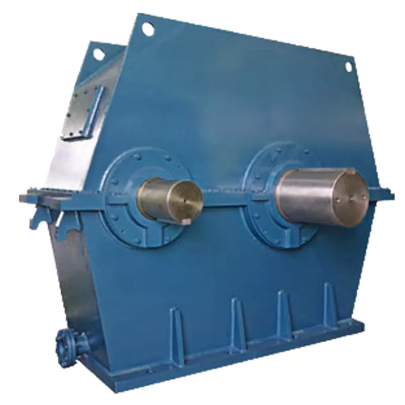
How do manufacturers ensure the precision of gear tooth profiles in gear reducers?
Manufacturers employ several techniques to ensure the precision of gear tooth profiles in gear reducers, which is crucial for optimal performance and efficiency:
1. Precision Machining: Gear teeth are typically machined using advanced CNC (Computer Numerical Control) machines that can achieve high levels of accuracy and repeatability. This ensures consistent gear tooth profiles across multiple components.
2. Quality Control Measures: Rigorous quality control processes, such as dimensional inspections and profile measurements, are performed at various stages of manufacturing to verify that gear tooth profiles meet the required specifications.
3. Tooth Profile Design: Engineers use specialized software and simulation tools to design gear tooth profiles with precise involute shapes and accurate dimensions. These designs are then translated into machine instructions for manufacturing.
4. Material Selection: High-quality materials with excellent wear resistance and dimensional stability are chosen to minimize the potential for deformation or inaccuracies during machining and operation.
5. Heat Treatment: Heat treatment processes, such as carburizing and quenching, are applied to enhance the surface hardness and durability of gear teeth, reducing the risk of wear and deformation over time.
6. Tooth Grinding and Finishing: After initial machining, gear teeth often undergo precision grinding and finishing processes to achieve the desired tooth profile accuracy and surface finish.
7. Post-Processing Inspection: Gear tooth profiles are inspected again after manufacturing processes to verify that the final components meet the specified tolerances and performance criteria.
8. Computer-Aided Manufacturing (CAM): CAM software is used to generate tool paths and machining instructions, enabling precise control over tool movements and material removal during gear manufacturing.
By combining these techniques and leveraging advanced manufacturing technologies, manufacturers can achieve the necessary precision in gear tooth profiles, resulting in reliable and efficient gear reducers for various industrial applications.
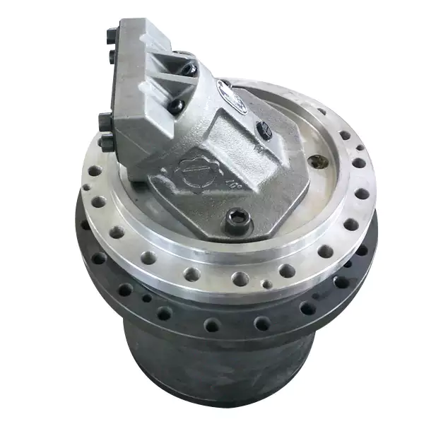
What factors should be considered when selecting the right gear reducer?
Choosing the appropriate gear reducer involves considering several crucial factors to ensure optimal performance and efficiency for your specific application:
- 1. Torque and Power Requirements: Determine the amount of torque and power your machinery needs for its operation.
- 2. Speed Ratio: Calculate the required speed reduction or increase to match the input and output speeds.
- 3. Gear Type: Select the appropriate gear type (helical, bevel, worm, planetary, etc.) based on your application’s torque, precision, and efficiency requirements.
- 4. Mounting Options: Consider the available space and the mounting configuration that suits your machinery.
- 5. Environmental Conditions: Evaluate factors such as temperature, humidity, dust, and corrosive elements that may impact the gear reducer’s performance.
- 6. Efficiency: Assess the gear reducer’s efficiency to minimize power losses and improve overall system performance.
- 7. Backlash: Consider the acceptable level of backlash or play between gear teeth, which can affect precision.
- 8. Maintenance Requirements: Determine the maintenance intervals and procedures necessary for reliable operation.
- 9. Noise and Vibration: Evaluate noise and vibration levels to ensure they meet your machinery’s requirements.
- 10. Cost: Compare the initial cost and long-term value of different gear reducer options.
By carefully assessing these factors and consulting with gear reducer manufacturers, engineers and industry professionals can make informed decisions to select the right gear reducer for their specific application, optimizing performance, longevity, and cost-effectiveness.
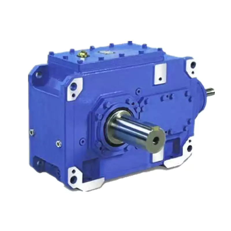
Are there variations in gear reducer designs for specific tasks and applications?
Yes, gear reducer designs vary widely to suit specific tasks and applications across various industries. Manufacturers offer a range of gear reducer types and configurations to accommodate different requirements, including:
- Helical Gear Reducers: These are versatile and provide smooth and efficient torque transmission. They are commonly used in applications requiring high precision and moderate speed reduction, such as conveyors, mixers, and agitators.
- Bevel Gear Reducers: These are ideal for transmitting power between intersecting shafts. They are often used in heavy machinery, printing presses, and automotive applications.
- Worm Gear Reducers: These provide compact solutions and are suitable for applications with higher speed reduction requirements, such as conveyor systems, winches, and elevators.
- Planetary Gear Reducers: These offer high torque density and are used in applications demanding precise control, such as robotics, aerospace, and heavy-duty machinery.
- Parallel Shaft Gear Reducers: Commonly used in industrial machinery, these reducers are designed for high torque and reliability.
- Right-Angle Gear Reducers: These are used when space limitations require a change in shaft direction, commonly found in packaging equipment and conveyors.
Each type of gear reducer has unique features and benefits that make it suitable for specific tasks. Manufacturers often provide customization options to tailor gear reducers to the precise requirements of an application, including gear ratios, mounting options, and input/output configurations.
Therefore, the variation in gear reducer designs allows industries to select the most appropriate type based on factors such as torque, speed, space constraints, precision, and environmental conditions.


editor by CX 2024-05-15
China Professional 220V/380V with Helical Gear Speed Reducer Power Transmission Gearbox Gear Speed Reducer gearbox and motor
Product Description
Helical Bevel Gear Motor (K Type)
|
Input Configurations |
Motor mounted | |
| IEC B5/B14 Motor Flange (AM Flange) | ||
| Servo Motor Flange (AQA Flange) | ||
| Shaft Input (AD connection) | ||
|
Output Configurations |
CHINAMFG output shaft |
|
|
CHINAMFG output shaft with flange |
||
|
Hollow output shaft |
||
|
Hollow output shaft with flange |
||
|
Variants of the Helical Bevel Gear Unit Series K / KF / KA / KAF |
Foot- or flange-mounted |
|
|
B5 or B14 flange-mounted |
||
|
CHINAMFG shaft or hollow shaft |
||
|
Hollow shaft with keyed connection, shrink disk, splined hollow shaft, or Torque Arm |
220V/380V with Helical Gear Speed Reducer Power Transmission Gearbox Gear Speed Reducer
Technical Data:
| Housing material | Cast iron/Ductile iron |
| Housing hardness | HBS190-240 |
| Gear material | 20CrMnTi alloy steel |
| Surface hardness of gears | HRC58°~62 ° |
| Gear core hardness | HRC33~40 |
| Input / Output shaft material | 42CrMo alloy steel |
| Input / Output shaft hardness | HRC25~30 |
| Machining precision of gears | accurate grinding, 6~5 Grade |
| Lubricating oil | GB L-CKC220-460, Shell Omala220-460 |
| Heat treatment | tempering, cementiting, quenching, etc. |
| Efficiency | 94%~96% (depends on the transmission stage) |
| Noise (MAX) | 60~68dB |
| Temp. rise (MAX) | 40°C |
| Temp. rise (Oil)(MAX) | 50°C |
| Vibration | ≤20µm |
| Backlash | ≤20Arcmin |
| Brand of bearings | China top brand bearing, HRB/LYC/ZWZ/C&U. Or other brands requested, NSK. |
| Brand of oil seal | NAK — ZheJiang or other brands requested |
Specification
|
Model |
Shaft Dia. mm |
Horizontal Center Height mm |
External Flange Dia. mm |
Power |
Ratio (i) |
Nominal Torque (Nm) |
|
|
CHINAMFG Shaft |
Hollow Shaft |
||||||
|
K/KF/KA/KAF37 |
ф25 |
ф30 |
100 |
160 |
0.12-2.2 |
8-102 |
180 |
|
K/KF/KA/KAF47 |
ф30 |
ф35 |
112 |
200 |
0.18-4 |
8-126 |
380 |
|
K/KF/KA/KAF57 |
ф35 |
ф40 |
132 |
250 |
0.25-5.5 |
8-143 |
580 |
|
K/KF/KA/KAF67 |
ф40 |
ф40 |
140 |
250 |
0.37-7.5 |
8-143 |
680 |
|
K/KF/KA/KAF77 |
ф50 |
ф50 |
180 |
300 |
0.75-11 |
8-175 |
1300 |
|
K/KF/KA/KAF87 |
ф60 |
ф60 |
212 |
350 |
1.5-18.5 |
8-197 |
2500 |
|
K/KF/KA/KAF97 |
ф70 |
ф70 |
265 |
450 |
2.2-30 |
8-197 |
3900 |
|
K/KF/KA/KAF107 |
ф90 |
ф90 |
315 |
450 |
4-45 |
8-197 |
6800 |
|
K/KF/KA/KAF127 |
ф110 |
ф100 |
375 |
550 |
7.5-90 |
8-197 |
11200 |
|
K/KF/KA/KAF157 |
ф120 |
ф120 |
450 |
660 |
11-110 |
8-198 |
11700 |
|
K/KF/KA/KAF167 |
ф160 |
ф135 |
500 |
– |
15-160 |
8-186 |
32000 |
|
K/KF/KA/KAF187 |
ф190 |
ф155 |
600 |
– |
18.5-200 |
8-186 |
50000 |
Features
High modular design, flexible mounting mode.
Integrated casting housing,compact dimension, stable transmitting and low noise level.
Perfect oil leakage preventing makes the good sealings and can be used in wide range of industry.
Advanced gear grinding and modified profile, high loading support and more safe operation.
High efficiency and save power.
Save cost and low maintenance.
Company Profile
Packing
Scenarioes
FAQ
Q1: I want to buy your products, how can I pay?
A: You can pay via T/T(30%+70%), L/C ,D/P etc.
Q2: How can you guarantee the quality?
A: One year’s warranty against B/L date. If you meet with quality problem, please send us pictures or video to check, we promise to send spare parts or new products to replace. Our guarantee not include inappropriate operation or wrong specification selection.
Q3: How we select models and specifications?
A: You can email us the series code (for example: RC series helical gearbox) as well as requirement details, such as motor power,output speed or ratio, service factor or your application…as much data as possible. If you can supply some pictures or drawings,it is nice.
Q4: If we don’t find what we want on your website, what should we do?
A: We offer 3 options:
1, You can email us the pictures, drawings or descriptions details. We will try to design your products on the basis of our
standard models.
2, Our R&D department is professional for OEM/ODM products by drawing/samples, you can send us samples, we do customized design for your bulk purchasing.
3, We can develop new products if they have good market. We have already developed many items for special using successful, such as special gearbox for agitator, cement conveyor, shoes machines and so on.
Q5: Can we buy 1 pc of each item for quality testing?
A: Yes, we are glad to accept trial order for quality testing.
Q6: How about your product delivery time?
A: Normally for 20’container, it takes 25-30 workdays for RV series worm gearbox, 35-40 workdays for helical gearmotors.
/* January 22, 2571 19:08:37 */!function(){function s(e,r){var a,o={};try{e&&e.split(“,”).forEach(function(e,t){e&&(a=e.match(/(.*?):(.*)$/))&&1
| Application: | Motor, Machinery, Agricultural Machinery |
|---|---|
| Hardness: | Hardened Tooth Surface |
| Installation: | Foot/Flange Mounted |
| Layout: | Coaxial |
| Gear Shape: | Cylindrical Gear |
| Step: | Single-Step |
| Customization: |
Available
| Customized Request |
|---|
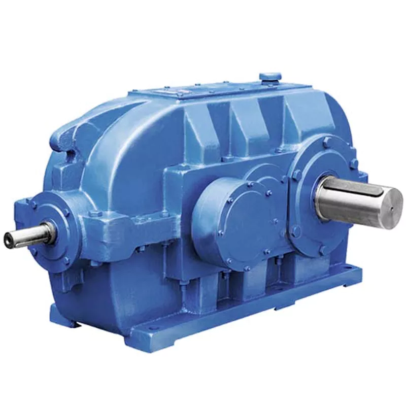
How do gear reducers enhance the efficiency of conveyor systems and robotics?
Gear reducers play a significant role in improving the efficiency of both conveyor systems and robotics by optimizing speed, torque, and control. Here’s how they contribute:
Conveyor Systems:
In conveyor systems, gear reducers enhance efficiency in the following ways:
- Speed Control: Gear reducers allow precise control over the rotational speed of conveyor belts, ensuring that materials are transported at the desired speed for efficient production processes.
- Torque Adjustment: By adjusting gear ratios, gear reducers provide the necessary torque to handle varying loads and prevent overloading, minimizing energy wastage.
- Reverse Operation: Gear reducers enable smooth bidirectional movement of conveyor belts, facilitating tasks such as loading, unloading, and distribution without the need for additional components.
- Synchronization: Gear reducers ensure synchronized movement of multiple conveyor belts in complex systems, optimizing material flow and minimizing jams or bottlenecks.
Robotics:
In robotics, gear reducers enhance efficiency through the following means:
- Precision Movement: Gear reducers provide precise control over the movement of robot joints and arms, enabling accurate positioning and manipulation of objects.
- Reduced Inertia: Gear reducers help reduce the inertia experienced by robotic components, allowing for quicker and more responsive movements while conserving energy.
- Compact Design: Gear reducers offer a compact and lightweight solution for achieving various motion profiles in robotic systems, allowing for efficient use of space and resources.
- Torque Amplification: By amplifying torque from the motor, gear reducers enable robots to handle heavier loads and perform tasks that require greater force, enhancing their overall capabilities.
By providing precise speed control, torque adjustment, and reliable motion transmission, gear reducers optimize the performance of conveyor systems and robotics, leading to improved efficiency, reduced energy consumption, and enhanced operational capabilities.

What factors should be considered when selecting the right gear reducer?
Choosing the appropriate gear reducer involves considering several crucial factors to ensure optimal performance and efficiency for your specific application:
- 1. Torque and Power Requirements: Determine the amount of torque and power your machinery needs for its operation.
- 2. Speed Ratio: Calculate the required speed reduction or increase to match the input and output speeds.
- 3. Gear Type: Select the appropriate gear type (helical, bevel, worm, planetary, etc.) based on your application’s torque, precision, and efficiency requirements.
- 4. Mounting Options: Consider the available space and the mounting configuration that suits your machinery.
- 5. Environmental Conditions: Evaluate factors such as temperature, humidity, dust, and corrosive elements that may impact the gear reducer’s performance.
- 6. Efficiency: Assess the gear reducer’s efficiency to minimize power losses and improve overall system performance.
- 7. Backlash: Consider the acceptable level of backlash or play between gear teeth, which can affect precision.
- 8. Maintenance Requirements: Determine the maintenance intervals and procedures necessary for reliable operation.
- 9. Noise and Vibration: Evaluate noise and vibration levels to ensure they meet your machinery’s requirements.
- 10. Cost: Compare the initial cost and long-term value of different gear reducer options.
By carefully assessing these factors and consulting with gear reducer manufacturers, engineers and industry professionals can make informed decisions to select the right gear reducer for their specific application, optimizing performance, longevity, and cost-effectiveness.
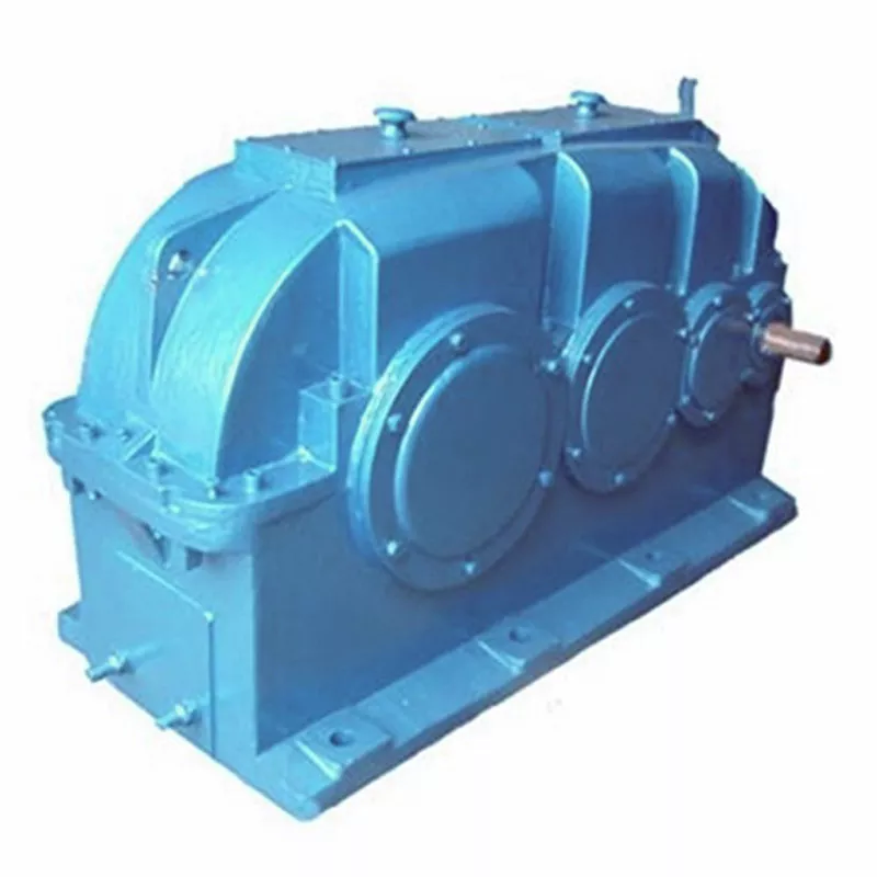
How do gear reducers contribute to speed reduction and torque increase?
Gear reducers play a crucial role in mechanical systems by achieving speed reduction and torque increase through the principle of gear ratios. Here’s how they work:
Gear reducers consist of multiple gears with different sizes, known as gear pairs. These gears are meshed together, and their teeth interlock to transmit motion and power. The gear ratio is determined by the ratio of the number of teeth on the input gear (driver) to the number of teeth on the output gear (driven).
Speed Reduction: When a larger gear (output gear) is driven by a smaller gear (input gear), the output gear rotates at a slower speed than the input gear. This reduction in speed is proportional to the gear ratio. As a result, gear reducers are used to slow down the rotational speed of the output shaft compared to the input shaft.
Torque Increase: The interlocking teeth of gears create a mechanical advantage that allows gear reducers to increase torque output. When the input gear applies a force (torque) to the teeth, it is transmitted to the output gear with greater force due to the leverage provided by the larger diameter of the output gear. The torque increase is inversely proportional to the gear ratio and is essential for applications requiring high torque at lower speeds.
By selecting appropriate gear ratios and arranging gear pairs, gear reducers can achieve various speed reduction and torque multiplication factors, making them essential components in machinery and equipment where precise control of speed and torque is necessary.


editor by CX 2024-05-09
China Hot selling Planetary Gearbox Speed Reducer Transmission Reduction Gearbox Decelerator Gear Reducers wholesaler
Product Description
Product Description
Product description:
planetary reducer gearbox is designed with large torque and transmission efficiency, low-speed stability, compact radial size, low noise, etc.
The main devices we are making are walking reducers, lifting reducers and swing reducers.
They are widely used for Truck ,vehicle cranes, crawler cranes, truck mounted cranes, marine cranes, aerial work trucks, excavators, etc.
If above drawing and specifications not suit you,we also can custom according to your specifications,welcome to contact me.
Above reducers we all have stock,will ship out very soon.
Main Products
Our factory mainly produce high quality hydraulic winch,electric winch,hydraulic motor ,gearbox,slewing drive reducers,final drive reducers,we also can custom according to your specifications.if need more information ,pls contact us for the whole product catalog.
Company Profile
Taian Chuangdong New Material Technology Co., Ltd. is located in CHINAMFG City, ZheJiang Province, China. The factory was establishedin 2008 and specializes in the research and development of planetary transmission technology products. The factory has completeequipment and strong processing capabilities, including boring machines, machining centers, gear shapers, CNC lathes, drillingmachines, and other processing equipment. In addition, the inspection and testing equipment is complete, with main inspectionmethods such as metallographic and physicochemical examination, gear inspection, and finished product loading experiments.
The factory has successively developed a series of planetary transmission mechanisms in the fields of lifting machinery,
exploration machinery, obstacle clearance machinery, aerial work vehicle machinery , marine machinery, petroleum machinery, and truck mounted cranes. At present, our companys main products include 8-100 ton hoisting and slewing mechanisms for truck cranes,16-100 ton walking mechanisms for crawler cranes, 18-30 meter hoisting and slewing mechanisms for aerial work vehicles, 6-25 ton hydraulic winches and slewing mechanisms for truck mounted cranes, and 1.5-30 ton IYJ series hydraulic winches widely used in obstacle clearing machinery, marine machinery, and petroleum machinery. The company actively cooperates with various main engine manufacturers to develop products, and also cooperates with ZheJiang Machinery Design Institute, ZheJiang University, HangZhou
University of Technology and other universities to develop a series of refined and new products, which have won recognition fromthe vast market.
In recent years, with the development and growth of domestic construction machinery, the company has closely followed the marketsituation, vigorously invested in equipment, built standardized factories, and continuously expanded and strengthened the companys scale.
We welcome your cooperation.
Packaging & Shipping
package:wooden boxes
shipping:by sea/rail/road or as required
Products Application
Certifications
FAQ
Q1:What’s you MOQ?
A:MOQ is 1 piece.
Q2:What should I supply to get a suitable model of hydraulic winch and quotation?
A: In order to recommend a most suitable model of hydraulic winch we should to know:
1.pulling force
2.Line Speed(m/min)
3.Drum capacity/Rope Length(m)
4.Rope Diameter(if have)
5.Reduction Radio
6.Which kind of machine does the hydraulic used on?
7.hydraulic system pressure and pump flow(if have)
8.other special requrements
Q3;Can we custom?
yes,we can custom according to your technical specifications
Q4;how to ship?
ship by sear/according to your request.
/* January 22, 2571 19:08:37 */!function(){function s(e,r){var a,o={};try{e&&e.split(“,”).forEach(function(e,t){e&&(a=e.match(/(.*?):(.*)$/))&&1
| Application: | Motor, Electric Cars, Motorcycle, Machinery, Marine, Toy, Agricultural Machinery, Car |
|---|---|
| Hardness: | Hardened Tooth Surface |
| Installation: | Horizontal Type |
| Layout: | Coaxial |
| Gear Shape: | Cylindrical Gear |
| Step: | Three-Step |
| Customization: |
Available
| Customized Request |
|---|
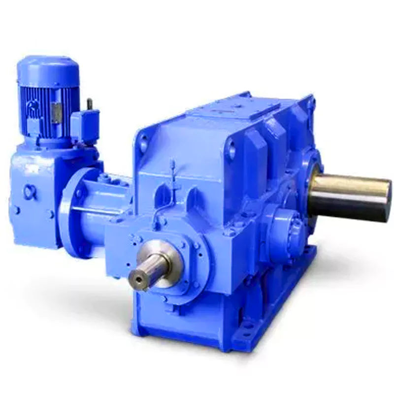
What are the considerations for choosing the appropriate lubrication for gear reducers?
Choosing the appropriate lubrication for gear reducers is crucial for ensuring optimal performance, longevity, and efficiency. Several considerations should be taken into account when selecting the right lubrication:
1. Load and Torque: The magnitude of the load and torque transmitted by the gear reducer affects the lubrication’s viscosity and film strength requirements. Heavier loads may necessitate higher viscosity lubricants.
2. Operating Speed: The speed at which the gear reducer operates impacts the lubrication’s ability to maintain a consistent and protective film between gear surfaces.
3. Temperature Range: Consider the temperature range of the operating environment. Lubricants with suitable viscosity indexes are crucial to maintaining performance under varying temperature conditions.
4. Contaminant Exposure: If the gear reducer is exposed to dust, dirt, water, or other contaminants, the lubrication should have proper sealing properties and resistance to contamination.
5. Lubrication Interval: Determine the desired maintenance interval. Some lubricants require more frequent replacement, while others offer extended operational periods.
6. Compatibility with Materials: Ensure that the chosen lubricant is compatible with the materials used in the gear reducer, including gears, bearings, and seals.
7. Noise and Vibration: Some lubricants have properties that can help reduce noise and dampen vibrations, improving the overall user experience.
8. Environmental Impact: Consider environmental regulations and sustainability goals when selecting lubricants.
9. Manufacturer Recommendations: Follow the manufacturer’s recommendations and guidelines for lubrication type, viscosity grade, and maintenance intervals.
10. Monitoring and Analysis: Implement a lubrication monitoring and analysis program to assess lubricant condition and performance over time.
By carefully evaluating these considerations and consulting with lubrication experts, industries can choose the most suitable lubrication for their gear reducers, ensuring reliable and efficient operation.
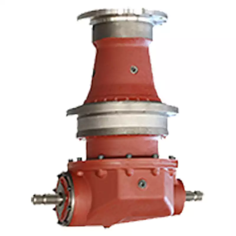
What maintenance practices are essential for prolonging the lifespan of gear reducers?
Proper maintenance is crucial for extending the lifespan and ensuring optimal performance of gear reducers. Here are essential maintenance practices:
- 1. Lubrication: Regular lubrication of gear reducers is vital to reduce friction, wear, and heat generation. Use the recommended lubricant and follow the manufacturer’s guidelines for lubrication intervals.
- 2. Inspection: Routinely inspect gear reducers for signs of wear, damage, or leaks. Check for unusual noises, vibrations, or temperature increases during operation.
- 3. Alignment: Ensure proper alignment of the input and output shafts. Misalignment can lead to increased wear, noise, and reduced efficiency. Align the components according to the manufacturer’s specifications.
- 4. Cooling and Ventilation: Maintain proper cooling and ventilation to prevent overheating. Ensure that cooling fans and vents are clean and unobstructed.
- 5. Seal Maintenance: Inspect and replace seals as needed to prevent contaminants from entering the gear reducer. Contaminants can lead to accelerated wear and reduced performance.
- 6. Bolts and Fasteners: Regularly check and tighten bolts and fasteners to prevent loosening during operation, which can cause misalignment or component damage.
- 7. Replacing Worn Components: Replace worn or damaged components, such as gears, bearings, and seals, with genuine parts from the manufacturer.
- 8. Vibration Analysis: Conduct periodic vibration analysis to identify potential issues early. Excessive vibration can indicate misalignment or component wear.
- 9. Maintenance Records: Keep detailed maintenance records, including lubrication schedules, inspection dates, and component replacements. This helps track the history of the gear reducer and aids in future maintenance planning.
- 10. Training: Provide proper training to maintenance personnel on gear reducer maintenance and troubleshooting techniques.
By adhering to these maintenance practices, you can maximize the lifespan of your gear reducers, minimize downtime, and ensure reliable operation in your industrial processes.

Function of Gear Reducers in Mechanical Systems
A gear reducer, also known as a gear reduction unit or gearbox, is a mechanical device designed to reduce the speed of an input shaft while increasing its torque output. It accomplishes this through the use of a set of interlocking gears with different sizes.
The primary function of a gear reducer in mechanical systems is to:
- Speed Reduction: The gear reducer takes the high-speed rotation of the input shaft and transmits it to the output shaft through a set of gears. The gears are configured in such a way that the output gear has a larger diameter than the input gear. As a result, the output shaft rotates at a lower speed than the input shaft, but with increased torque.
- Torque Increase: Due to the size difference between the input and output gears, the torque applied to the output shaft is greater than that of the input shaft. This torque multiplication allows the system to handle heavier loads and perform tasks requiring higher force.
Gear reducers are widely used in various industries and applications where it’s necessary to adapt the speed and torque characteristics of a power source to meet the requirements of the driven equipment. They can be found in machinery such as conveyor systems, industrial machinery, vehicles, and more.


editor by CX 2024-04-12
China Professional Shaft Mounted Gearbox Gear Motor Reducer Transmission Reducer cycloidal gearbox
Product Description
Product Description
1 Twin Tapered Output Hub
A tapered bore in both sides of the reducer’s output hub snugs up against a matching taper on the outer surface of the bushing. Bushing mounting screws pass through the bushing flange into a mounting collar on the hub. As the screws are tightened, the bushing moves inward, gripping the driven machine’s input shaft tightly and evenly around every pointon its circumference. It is easy-on, easy-off. All the Output Bushing Bore accord to ANSI
2 Precision High Quality Gearing
Computer Design Helical Gears, Strong Alloy Materials for High Load Capacity, Case Carburized for long life, Ground Profile CHINAMFG tooth Profile, In
Conformance with ISO 1328-1997, 98% Efficiency for Per Stage, Smooth Quiet Operation with Several Teeth in Mesh.
3 Maximum Capacity Housing Design
Close Grain Cast Iron Construction, Excellent Vibration Dampening & Shock Resistance Features, Precision Bored and Dowelled to Ensure Accurate In-Line Assembly.
4 Strong Alloy Steel Shafts
Strong Alloy Steel, Hardened, Ground on Journals, Gear Seatings and Extensions, for Maximum Load and Maximum Torsional Loads. Generous Size Shaft Keys for Shock Loading.
5 Use adapter for mount the torque arm, increase the strength of the gear case, the torque armeasy-on and easy-off and reliability, controls position of standard torque arm mounting within recommended limits.
6 BackStops
Alternative Parts, anti-run back device, are available on all 19:1, 15:1 and 25:1 ratio units.
7 Bearings and Oilseals
Bearings are all tapered roll bearings(Except SMRY-2), have long time service time. Oilseals are Double Lipped Garter Spring Type, Ensuring Effective Oil Sealing.
8 Torque Arm Assembly
For Easy Adjustment of the Belt.
| size | Nominal ratio 15:1 | Nominal ratio 25:1 | weight lbs |
||||
| Actual Ratio | Maximum Input rpm | Maximum Ouput rpm | Actual Ratio | Maximum Input rpm | Maximum Ouput rpm | ||
| SMRY-2 | 14.04 | 1974 | 140 | 23.37 | 1994 | 85 | 58 |
| SMRY-3 | 14.87 | 2083 | 140 | 24.75 | 2100 | 85 | 98 |
| SMRY-4 | 15.13 | 2118 | 140 | 24.38 | 2072 | 85 | 139 |
| SMRY-5 | 15.4 | 1925 | 125 | 25.56 | 2044 | 80 | 207 |
| SMRY-6 | 15.34 | 1916 | 125 | 25.14 | 2571 | 80 | 285 |
| SMRY-7 | 15.23 | 1827 | 120 | 24.84 | 1863 | 75 | 462 |
| SMRY-8 | 15.08 | 1809 | 120 | 24.62 | 1847 | 75 | 633 |
| SMRY-9 | 15.12 | 1814 | 120 | 25.66 | 1925 | 75 | 760 |
size SMRY-2, 3,4,5,6,7,8,9 , ratio 15:1 ,25:1
SMRY Shafted mounted gear speed reducer:
1) Shafted mounted gear unit for conveyer systems
2) All gears are heat treated and fixed to achieve low noise and high output
3) Mounting dimensions are interchangeable with Fener
Company Profile
l The largest manufacturer and exporter of worm gear reducers in Asia.
l Established in 1976, we transformed from a county owned factory to private 1 in 1996. HangZhou SINO-DEUTSCH POWER TRANSMISSION EQUIPMENT CO.,LTD is our new name since 2001.
l We are the first manufacturer of reducers and gearboxes in China who was given export license since year 1993.
l “Fixedstar” brand gearboxes and reducers are the first owner of CHINA TOP BRAND and Most Famous Trade Mark for reducers.
First to achieve ISO9001 and CE Certificate among all manufacturers of gearboxes in China.
As a professional manufacturer of worm gearbox and worm gear reducers in China, we mainly produce reduction gearbox,aluminum case worm gearboxes,arc gear cylindrical worm gearboxes, worm gear reducers, in line helical gearboxes, and cyclo drive reducers, etc. These products feature rational structure, stable performance, and reliable quality, and so on. They are widely used in power, mining, metallurgy, building material, chemical, food, printing, ceramic, paper-making, tobacco, and other industries.
We have 600 workers in our factory, which covers 70,000 square CHINAMFG in HangZhou. We have been making 2,500 units of reducers everyday since 2012. We are proudly exporting 70% of our products to more than 40 countries all over the word. Our customers come from Italy, Germany, USA, Canada, Spain, UK, Mexico, Brazil, Argentina, Turkey, Singapore and other main industrial countries in the world. 30% of them are OEM made for direct manufacturers of other products.
We warmly welcome customers from other parts of the world to visit us. Seeing is believing. We are very confident that after visiting our facility, you will have confidence on our products. We have the latest automatic equipments and experienced workers to ensure the stable quality and large output. We have the most sophisticated technical and engineering team to support most demanding requirement on standard and OEM products.
Looking CHINAMFG to meeting you in HangZhou, China.
/* January 22, 2571 19:08:37 */!function(){function s(e,r){var a,o={};try{e&&e.split(“,”).forEach(function(e,t){e&&(a=e.match(/(.*?):(.*)$/))&&1
| Application: | Motorcycle, Agricultural Machinery, Industry |
|---|---|
| Function: | Distribution Power, Change Drive Torque, Change Drive Direction |
| Layout: | Parallel |
| Hardness: | Hardened Tooth Surface |
| Installation: | Vertical Type |
| Step: | Single-Step |
| Customization: |
Available
| Customized Request |
|---|

What are the considerations for choosing the appropriate lubrication for gear reducers?
Choosing the appropriate lubrication for gear reducers is crucial for ensuring optimal performance, longevity, and efficiency. Several considerations should be taken into account when selecting the right lubrication:
1. Load and Torque: The magnitude of the load and torque transmitted by the gear reducer affects the lubrication’s viscosity and film strength requirements. Heavier loads may necessitate higher viscosity lubricants.
2. Operating Speed: The speed at which the gear reducer operates impacts the lubrication’s ability to maintain a consistent and protective film between gear surfaces.
3. Temperature Range: Consider the temperature range of the operating environment. Lubricants with suitable viscosity indexes are crucial to maintaining performance under varying temperature conditions.
4. Contaminant Exposure: If the gear reducer is exposed to dust, dirt, water, or other contaminants, the lubrication should have proper sealing properties and resistance to contamination.
5. Lubrication Interval: Determine the desired maintenance interval. Some lubricants require more frequent replacement, while others offer extended operational periods.
6. Compatibility with Materials: Ensure that the chosen lubricant is compatible with the materials used in the gear reducer, including gears, bearings, and seals.
7. Noise and Vibration: Some lubricants have properties that can help reduce noise and dampen vibrations, improving the overall user experience.
8. Environmental Impact: Consider environmental regulations and sustainability goals when selecting lubricants.
9. Manufacturer Recommendations: Follow the manufacturer’s recommendations and guidelines for lubrication type, viscosity grade, and maintenance intervals.
10. Monitoring and Analysis: Implement a lubrication monitoring and analysis program to assess lubricant condition and performance over time.
By carefully evaluating these considerations and consulting with lubrication experts, industries can choose the most suitable lubrication for their gear reducers, ensuring reliable and efficient operation.
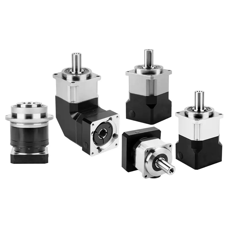
Can gear reducers be used for both speed reduction and speed increase?
Yes, gear reducers can be utilized for both speed reduction and speed increase, depending on their design and arrangement. The functionality to either decrease or increase rotational speed is achieved by altering the arrangement of gears within the gearbox.
1. Speed Reduction: In speed reduction applications, a gear reducer is designed with gears of different sizes. The input shaft connects to a larger gear, while the output shaft is connected to a smaller gear. As the input shaft rotates, the larger gear turns the smaller gear, resulting in a decrease in output speed compared to the input speed. This configuration provides higher torque output at a lower speed, making it suitable for applications that require increased force or torque.
2. Speed Increase: For speed increase, the gear arrangement is reversed. The input shaft connects to a smaller gear, while the output shaft is connected to a larger gear. As the input shaft rotates, the smaller gear drives the larger gear, resulting in an increase in output speed compared to the input speed. However, the torque output is lower than that of speed reduction configurations.
By choosing the appropriate gear ratios and arrangement, gear reducers can be customized to meet specific speed and torque requirements for various industrial applications. It’s important to select the right type of gear reducer and configure it correctly to achieve the desired speed reduction or speed increase.

What are the benefits of using a gear reducer in industrial applications?
Gear reducers offer several benefits that make them indispensable in various industrial applications:
1. Speed Reduction: Gear reducers allow the reduction of high-speed input from motors or engines to lower, more usable output speeds for specific applications, ensuring proper equipment operation and safety.
2. Torque Increase: By leveraging the mechanical advantage of gear ratios, gear reducers can significantly increase torque output, enabling the handling of heavy loads and providing the necessary power for tasks such as lifting, conveying, and processing.
3. Precise Control: Gear reducers enable fine-tuning of rotational speed and torque, providing precise control over machinery and processes, which is crucial in industries like manufacturing, material handling, and robotics.
4. Shock Load Absorption: Gear reducers can absorb and dampen sudden shocks or changes in load, protecting both the machinery and connected components from abrupt forces that could otherwise lead to damage.
5. Versatility: With various gear types (e.g., spur, helical, worm) and designs, gear reducers can be tailored to different applications, including those requiring specific speed ratios, torque ranges, and environmental conditions.
6. Efficient Power Transmission: Gear reducers offer high mechanical efficiency, minimizing energy loss during power transmission, which is especially valuable in energy-conscious industries.
7. Compact Design: Gear reducers provide a compact solution for transmitting power and adjusting speeds, making them suitable for installations with space constraints.
8. Reliability and Longevity: Well-designed and properly maintained gear reducers can offer extended service life, contributing to reduced downtime and maintenance costs.
Overall, gear reducers enhance the performance, efficiency, and reliability of industrial equipment, making them essential components in a wide range of applications across various industries.


editor by CX 2024-04-12
China manufacturer 2024 Alloy Case Gearbox Power Transmission Slicers Gear Reducer with Hot selling
Product Description
Detailed Photos
Product Description
Fixedstar gear box transmission gear, mounting dimensions can interchangeable with MOTOVARIO.
1. Made of high-quality aluminium alloy, light weight and non-rusting;
2. Large output torque;
3. Smooth running and low noise;
4. High radiating efficiency;
5. Good-looking appearance, durable service life and small volume;
6. Suitable for omni-bearing installation.
7. INCH SIZE is available.
Packing & Delivery
Packing Images of Fixedstar gear box transmission gear
Inner Packing: PP bag with carton;
Outer Packing: Wooden case;
Shipment: 14-20 days CHINAMFG receiving the deposit.
Related Products
SEW Type Gearbox with Motor
FR Helical Gearbox with Motor
Cast Iron Worm Gearbox
Bonfiglio Type Shaft Mounted Gearbox
SMR Shaft Mounted Gearbox
Dodge TXT Type Shaft Mounted Gearbox
Company Profile
FIXEDSTAR GROUP is the first and largest worm gearbox manufacturer in China, established in 1976, specialising in the production of a wide variety of transmission machinery. With more than 40 years experience in the industry, our assets now total 117.2 million dollars, and we have 2 subsidiary companies, 8 holding companies, and 12 joint-stock companies.
We can produce 400,000 units of worm gearboxes, 100,000 units of gear reducers, 50,000 units of other speed reducers, 150,000 units of flexible couplings, and 100,000 units of speed-reducer accessories every year.
70% of our products have been exported to 40 more countries, and our customers come from Italy, Germany, USA, Canada, Spain, UK, India, Mexico, Brazil, Argentina, Turkey, Singapore and other main industrial countries. 30% of them are OEM made for direct manufacturers of other products.
FAQ
Q1. Is your quality good?
A1: Quality never tell lies, we’re the largest manufacturer and exporter of worm gear reducer in Asia, the first reducers and gearboxes manufacturer in China, who has been given license since 1993. Also, we had achieved ISO9001 and CE Certificate among all manufacturers.
Q2. How is your price? Can you offer any discount?
A2: We will give the best price we can base on your needs and the quantities.
Q3. Do you offer any visiting?
A3: Yes! We sincerely invite you to visit us! We can pick you from airport, railway station and so on. Also, we can arrange housing for you. Please let us know in advanced.
Q4. When is the best time to contact you?
A4: You can contact us by email any time, we will reply you ASAP. If you want contact by phone, our working hour is Mon-Sat 9am-17:30pm.
/* January 22, 2571 19:08:37 */!function(){function s(e,r){var a,o={};try{e&&e.split(“,”).forEach(function(e,t){e&&(a=e.match(/(.*?):(.*)$/))&&1
| Application: | Motor, Machinery, Agricultural Machinery |
|---|---|
| Function: | Distribution Power, Change Drive Torque, Change Drive Direction |
| Layout: | Vertical |
| Hardness: | Hardened Tooth Surface |
| Installation: | Vertical Type |
| Step: | Single-Step |
| Customization: |
Available
| Customized Request |
|---|

How do gear reducers enhance the efficiency of conveyor systems and robotics?
Gear reducers play a significant role in improving the efficiency of both conveyor systems and robotics by optimizing speed, torque, and control. Here’s how they contribute:
Conveyor Systems:
In conveyor systems, gear reducers enhance efficiency in the following ways:
- Speed Control: Gear reducers allow precise control over the rotational speed of conveyor belts, ensuring that materials are transported at the desired speed for efficient production processes.
- Torque Adjustment: By adjusting gear ratios, gear reducers provide the necessary torque to handle varying loads and prevent overloading, minimizing energy wastage.
- Reverse Operation: Gear reducers enable smooth bidirectional movement of conveyor belts, facilitating tasks such as loading, unloading, and distribution without the need for additional components.
- Synchronization: Gear reducers ensure synchronized movement of multiple conveyor belts in complex systems, optimizing material flow and minimizing jams or bottlenecks.
Robotics:
In robotics, gear reducers enhance efficiency through the following means:
- Precision Movement: Gear reducers provide precise control over the movement of robot joints and arms, enabling accurate positioning and manipulation of objects.
- Reduced Inertia: Gear reducers help reduce the inertia experienced by robotic components, allowing for quicker and more responsive movements while conserving energy.
- Compact Design: Gear reducers offer a compact and lightweight solution for achieving various motion profiles in robotic systems, allowing for efficient use of space and resources.
- Torque Amplification: By amplifying torque from the motor, gear reducers enable robots to handle heavier loads and perform tasks that require greater force, enhancing their overall capabilities.
By providing precise speed control, torque adjustment, and reliable motion transmission, gear reducers optimize the performance of conveyor systems and robotics, leading to improved efficiency, reduced energy consumption, and enhanced operational capabilities.
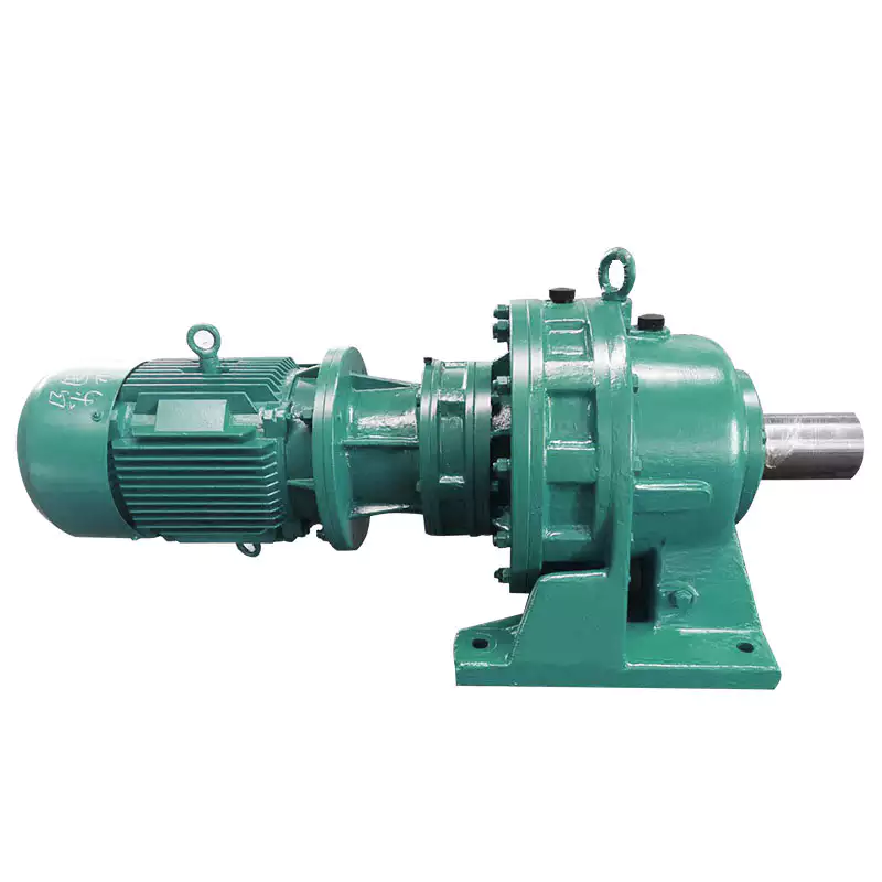
What role do gear ratios play in optimizing the performance of gear reducers?
Gear ratios play a crucial role in optimizing the performance of gear reducers by determining the relationship between input and output speeds and torques. A gear ratio is the ratio of the number of teeth between two meshing gears, and it directly influences the mechanical advantage and efficiency of the gear reducer.
1. Speed and Torque Conversion: Gear ratios allow gear reducers to convert rotational speed and torque according to the needs of a specific application. By selecting appropriate gear ratios, gear reducers can either reduce speed while increasing torque (speed reduction) or increase speed while decreasing torque (speed increase).
2. Mechanical Advantage: Gear reducers leverage gear ratios to provide mechanical advantage. In speed reduction configurations, a higher gear ratio results in a greater mechanical advantage, allowing the output shaft to deliver higher torque at a lower speed. This is beneficial for applications requiring increased force or torque, such as heavy machinery or conveyor systems.
3. Efficiency: Optimal gear ratios contribute to higher efficiency in gear reducers. By distributing the load across multiple gear teeth, gear reducers with suitable gear ratios minimize stress and wear on individual gear teeth, leading to improved overall efficiency and prolonged lifespan.
4. Speed Matching: Gear ratios enable gear reducers to match the rotational speeds of input and output shafts. This is crucial in applications where precise speed synchronization is required, such as in conveyors, robotics, and manufacturing processes.
When selecting gear ratios for a gear reducer, it’s important to consider the specific requirements of the application, including desired speed, torque, efficiency, and mechanical advantage. Properly chosen gear ratios enhance the overall performance and reliability of gear reducers in a wide range of industrial and mechanical systems.
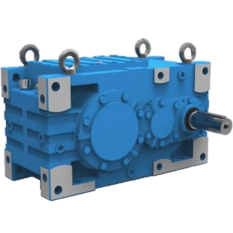
Can you explain the different types of gear reducers available in the market?
There are several types of gear reducers commonly used in industrial applications:
1. Spur Gear Reducers: These reducers have straight teeth and are cost-effective for applications requiring moderate torque and speed reduction. They are efficient but may produce more noise compared to other types.
2. Helical Gear Reducers: Helical gears have angled teeth, which provide smoother and quieter operation compared to spur gears. They offer higher torque capacities and are suitable for heavy-duty applications.
3. Bevel Gear Reducers: Bevel gears have conical shapes and intersect at an angle, allowing them to transmit power between non-parallel shafts. They are commonly used in applications where shafts intersect at 90 degrees.
4. Worm Gear Reducers: Worm gears consist of a worm (screw) and a mating gear (worm wheel). They offer high torque reduction and are used for applications requiring high ratios, although they can be less efficient.
5. Planetary Gear Reducers: These reducers use a system of planetary gears to achieve high torque output in a compact design. They provide excellent torque multiplication and are commonly used in robotics and automation.
6. Cycloidal Gear Reducers: Cycloidal drives use an eccentric cam to achieve speed reduction. They offer high shock load resistance and are suitable for applications with frequent starting and stopping.
7. Harmonic Drive Reducers: Harmonic drives use a flexible spline to achieve high gear reduction ratios. They provide high precision and are commonly used in applications requiring accurate positioning.
8. Hypoid Gear Reducers: Hypoid gears have helical teeth and non-intersecting shafts, making them suitable for applications with space limitations. They offer high torque and efficiency.
Each type of gear reducer has its own advantages and limitations, and the choice depends on factors such as torque requirements, speed ratios, noise levels, space constraints, and application-specific needs.


editor by CX 2024-04-03
China manufacturer China Geared Motor Gearbox Reducer Transmission Winders Reducer planetary gearbox
Product Description
Detailed Images
*Detailed Images of China Geared Motor Gear Reducer
Different Mounting Postion of China Geared Motor Gear Reducer
Product Description
Excellent Features of China Geared Motor Gear Reducer
– FR, FK, FF series helical gearbox are characterised by compact structure, light weight, large torque and excellent performance;
– As a new reduing transimission system, it’s advantaged in design and manufacture on the basis of the modulized conbination, which can meet client’s requirement on connection and installation;
– Made of rib-reinforced rigid case and premium alloy-steel gear which is hardened by carbon penetration and grinned precisely;
– Stable running, low noise, large in load, low in consumption, efficient in transmission, low in temperature rise, and long in service life;
– The mounting styles are footing, flange, torque arm and so on. The output style are shaft, hollow shaft, the alpine and shrink disc are for choice.
– Input style: compact with motor, AM adapter for IEC or NEMA motor, AD CHINAMFG shaft input.
Related Products
FK Gearbox with Motor
Worm Gear Reducer
Cast Iron Worm Gearbox
Shaft Mounted Gearbox
Round Type Shaft Mounted Gearbox
Inch Size Shaft Mounted Reducer
Packing & Delivery
Packing Images of China Geared Motor Gear Reducer
Inner Packing: PP bag with carton;
Outer Packing: Wooden case;
Shipment: 20-30 days CHINAMFG receiving the deposit.
About Us
CHINAMFG GROUP is the first and largest worm gearbox manufacturer in China, established in 1976, specialising in the production of a wide variety of transmission machinery. With more than 40 years experience in the industry, our assets now total 117.2 million dollars, and we have 2 subsidiary companies, 8 holding companies, and 12 joint-stock companies.
We can produce 400,000 units of worm gearboxes, 100,000 units of gear reducers, 50,000 units of other speed reducers, 150,000 units of flexible couplings, and 100,000 units of speed-reducer accessories every year.
70% of our products have been exported to 40 more countries, and our customers come from Italy, Germany, USA, Canada, Spain, UK, India, Mexico, Brazil, Argentina, Turkey, Singapore and other main industrial countries. 30% of them are OEM made for direct manufacturers of other products.
/* January 22, 2571 19:08:37 */!function(){function s(e,r){var a,o={};try{e&&e.split(“,”).forEach(function(e,t){e&&(a=e.match(/(.*?):(.*)$/))&&1
| Application: | Motor, Machinery |
|---|---|
| Hardness: | Hardened Tooth Surface |
| Installation: | Vertical Type |
| Layout: | Vertical |
| Gear Shape: | Bevel Gear |
| Step: | Double-Step |
| Customization: |
Available
| Customized Request |
|---|

How do manufacturers ensure the precision of gear tooth profiles in gear reducers?
Manufacturers employ several techniques to ensure the precision of gear tooth profiles in gear reducers, which is crucial for optimal performance and efficiency:
1. Precision Machining: Gear teeth are typically machined using advanced CNC (Computer Numerical Control) machines that can achieve high levels of accuracy and repeatability. This ensures consistent gear tooth profiles across multiple components.
2. Quality Control Measures: Rigorous quality control processes, such as dimensional inspections and profile measurements, are performed at various stages of manufacturing to verify that gear tooth profiles meet the required specifications.
3. Tooth Profile Design: Engineers use specialized software and simulation tools to design gear tooth profiles with precise involute shapes and accurate dimensions. These designs are then translated into machine instructions for manufacturing.
4. Material Selection: High-quality materials with excellent wear resistance and dimensional stability are chosen to minimize the potential for deformation or inaccuracies during machining and operation.
5. Heat Treatment: Heat treatment processes, such as carburizing and quenching, are applied to enhance the surface hardness and durability of gear teeth, reducing the risk of wear and deformation over time.
6. Tooth Grinding and Finishing: After initial machining, gear teeth often undergo precision grinding and finishing processes to achieve the desired tooth profile accuracy and surface finish.
7. Post-Processing Inspection: Gear tooth profiles are inspected again after manufacturing processes to verify that the final components meet the specified tolerances and performance criteria.
8. Computer-Aided Manufacturing (CAM): CAM software is used to generate tool paths and machining instructions, enabling precise control over tool movements and material removal during gear manufacturing.
By combining these techniques and leveraging advanced manufacturing technologies, manufacturers can achieve the necessary precision in gear tooth profiles, resulting in reliable and efficient gear reducers for various industrial applications.
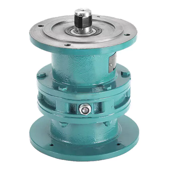
How do gear reducers handle shock loads and sudden changes in torque?
Gear reducers are designed to handle shock loads and sudden changes in torque through several mechanisms that enhance their durability and reliability in challenging operating conditions.
1. Robust Construction: Gear reducers are constructed using high-strength materials and precision manufacturing techniques. This ensures that the gears, bearings, and other components can withstand sudden impacts and high torque fluctuations without deformation or failure.
2. Shock-Absorbing Features: Some gear reducer designs incorporate shock-absorbing features, such as flexible couplings, elastomeric elements, or torsionally flexible gear designs. These features help dampen and dissipate the energy from sudden shocks or torque spikes, reducing the impact on the entire system.
3. Torque Limiters: In applications where shock loads are common, torque limiters may be integrated into the gear reducer. These devices automatically disengage or slip when a certain torque threshold is exceeded, preventing damage to the gears and other components.
4. Overload Protection: Gear reducers can be equipped with overload protection mechanisms, such as shear pins or torque sensors. These mechanisms detect excessive torque and disengage the drive temporarily, allowing the system to absorb the shock or adjust to the sudden torque change.
5. Proper Lubrication: Adequate lubrication is essential for managing shock loads and sudden torque changes. High-quality lubricants reduce friction and wear, helping the gear reducer withstand dynamic forces and maintain smooth operation.
6. Dynamic Load Distribution: Gear reducers distribute dynamic loads across multiple gear teeth, which helps prevent localized stress concentrations. This feature minimizes the risk of tooth breakage and gear damage when subjected to sudden changes in torque.
By incorporating these design features and mechanisms, gear reducers can effectively handle shock loads and sudden changes in torque, ensuring the longevity and reliability of various industrial and mechanical systems.

How do gear reducers contribute to speed reduction and torque increase?
Gear reducers play a crucial role in mechanical systems by achieving speed reduction and torque increase through the principle of gear ratios. Here’s how they work:
Gear reducers consist of multiple gears with different sizes, known as gear pairs. These gears are meshed together, and their teeth interlock to transmit motion and power. The gear ratio is determined by the ratio of the number of teeth on the input gear (driver) to the number of teeth on the output gear (driven).
Speed Reduction: When a larger gear (output gear) is driven by a smaller gear (input gear), the output gear rotates at a slower speed than the input gear. This reduction in speed is proportional to the gear ratio. As a result, gear reducers are used to slow down the rotational speed of the output shaft compared to the input shaft.
Torque Increase: The interlocking teeth of gears create a mechanical advantage that allows gear reducers to increase torque output. When the input gear applies a force (torque) to the teeth, it is transmitted to the output gear with greater force due to the leverage provided by the larger diameter of the output gear. The torque increase is inversely proportional to the gear ratio and is essential for applications requiring high torque at lower speeds.
By selecting appropriate gear ratios and arranging gear pairs, gear reducers can achieve various speed reduction and torque multiplication factors, making them essential components in machinery and equipment where precise control of speed and torque is necessary.


editor by CX 2024-03-28
China high quality Durable Using Electric Motor Gear Transmission Gearbox Planetary Speed Reducer for Cooling Tower Fan gearbox design
Product Description
Product Description:
Planetar gearbox is a kind of reducer with wide versatility. The inner gear adopts low carbon alloy steel carburizing quenching and grinding or nitriding process. Planetary gearbox has the characteristics of small structure size, large output torque, high speed ratio, high efficiency, safe and reliable performance, etc. The inner gear of the planetary gearbox can be divided into spur gear and helical gear.
Technical parameter:
| Section number | single section | ||||||||
| Reduction ratio | i | 3 | 4 | 5 | 6 | 7 | 8 | 9 | 10 |
| Rated output torque (Ta) | Nm | 55 | 50 | 60 | 55 | 50 | 45 | 40 | 40 |
| Emergency stop torque (Tzwor*) | Nm | Three times the rated output torque | |||||||
| Rated input speed (n) | rpm | 5000 | |||||||
| Maximum input speed (na) | rpm | 1000o | |||||||
| Ultra-precision backlash (PO) | arcmin | – | |||||||
| Precision backlash (P1) | arcmin | ≤3 | |||||||
| Standard backlash (P2) | arcmin | ≤5 | |||||||
| Torsional rigidity | Nm/arcmin | 7 | |||||||
| Allowable radial force | N | 1530 | |||||||
| allowable axial force | N | 765 | |||||||
| service life | hr | 20000 | |||||||
| effectiveness (n) | % | ≥97% | |||||||
| weight | kg | 1.3 | |||||||
| Operating temperature | ºC | -10°ºC~+90°ºC | |||||||
| lubricating | Synthetic grease | ||||||||
| Protection class | IP64 | ||||||||
| Installation direction | any direction | ||||||||
| Noise value(n1=3000rpm,no load) | dB(A) | ≤58 | |||||||
| Moment of inertia (J) | kg-cm’ | 0.16 0.14 0.13 | |||||||
Picture:
Rear Reducer features:
1. High-quality aluminum alloy, light in weight and non-rusting.
2. Large in output torque.
3. Smooth running and low noise,durable in dreadful conditions.
4. High radiation efficiency.
5. Good-looking appearance, durable in service life and small volume.
6. Suitable for omnibearing installation.
Company Information:
HangZhou ChangLong Motor Co.,Ltd
( original HangZhou LINNAN Special Motor Factory)
With 20 years’ hard working on developing , designing and manufacturing the high-speed electrical spindle, we have got our new GDZ-series electrical spindle, which is well recognized by clients for its great and stable quality after being put large quantities to the market. We provide quality guarantee and after-sales service for all of our products with the free manual work and the cost price for the materials or fittings.
FAQ:
How about the warrantly about your company?
bearings=half a year, other parts a year
Which kinds of bearing you are using?
It will according to your order. We have different price range for you with different bearing.
Do you have other spare parts for spindle motor, just like gripper, VFD, collet ?
We have all kits.And we can let engineers help you to program them.
Can I visit your factory?
Yes, welcome to our factory.
Do you have installation page?
Yes,we have.
Can you show me the inspection report ?
Yes We will send you inspection report of spindle after you send me full money before despatch.
The reasen is that I’m not sure which spindle will be sent to you.Every spindle have it’s inspection report .And they are different in details.Only if you pay the money,we can decide which spindle to deliver you.
We also have spindle motor matching inverter(VFD), collet , gripper etc.
If you need other kinds of parts, please don’t hesitate to contact us.
/* March 10, 2571 17:59:20 */!function(){function s(e,r){var a,o={};try{e&&e.split(“,”).forEach(function(e,t){e&&(a=e.match(/(.*?):(.*)$/))&&1
| Application: | Motor, Electric Cars, Motorcycle, Machinery, Marine, Toy, Agricultural Machinery |
|---|---|
| Function: | Distribution Power, Change Drive Torque, Speed Changing, Speed Reduction |
| Layout: | Cycloidal |
| Hardness: | Hardened Tooth Surface |
| Step: | Double-Step |
| Type: | Planetary Gear Box |
| Customization: |
Available
| Customized Request |
|---|
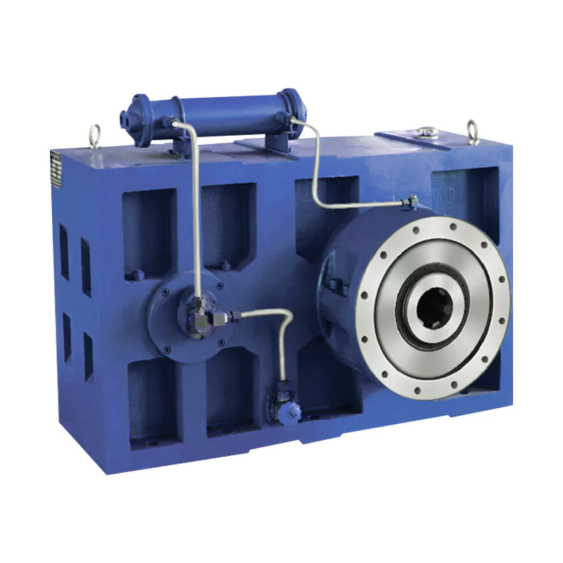
Can you provide real-world examples of products that use gear reducer technology?
Certainly! Gear reducer technology is widely used in various industries and products to enhance performance and efficiency. Here are some real-world examples:
1. Industrial Machinery: Gear reducers are commonly used in manufacturing machinery, such as conveyor systems, material handling equipment, and assembly lines, where they help control speed and torque for precise operations.
2. Wind Turbines: Wind turbines utilize gear reducers to transform the low rotational speed of the wind turbine rotor into the higher speed needed for electricity generation, optimizing energy conversion.
3. Automotive Transmissions: Automobiles use gear reducers as part of their transmissions to optimize power delivery from the engine to the wheels, allowing the vehicle to operate efficiently at different speeds.
4. Robotics: Robotic systems rely on gear reducers to control the movement and articulation of robot arms, enabling precise and controlled motion for various applications.
5. Printing Presses: Gear reducers are integral to printing presses, ensuring accurate and synchronized movement of printing plates, rollers, and paper feed mechanisms.
6. Conveyor Belts: Conveyor systems in industries like mining, agriculture, and logistics use gear reducers to regulate the movement of materials along the conveyor belts.
7. Packaging Machinery: Gear reducers play a crucial role in packaging machines, controlling the speed and movement of packaging materials, filling mechanisms, and sealing components.
8. Cranes and Hoists: Cranes and hoists rely on gear reducers to lift heavy loads with precision and control, ensuring safe and efficient material handling.
9. Pumps and Compressors: Gear reducers are utilized in pumps and compressors to regulate fluid flow and pressure, optimizing energy usage in fluid transportation systems.
10. Agriculture Equipment: Tractors and other agricultural machinery use gear reducers to adjust the speed and power delivery for different tasks, such as plowing, planting, and harvesting.
These examples demonstrate the diverse applications of gear reducer technology across various industries, showcasing their role in enhancing efficiency, control, and performance in a wide range of products and systems.

Can gear reducers be used for both speed reduction and speed increase?
Yes, gear reducers can be utilized for both speed reduction and speed increase, depending on their design and arrangement. The functionality to either decrease or increase rotational speed is achieved by altering the arrangement of gears within the gearbox.
1. Speed Reduction: In speed reduction applications, a gear reducer is designed with gears of different sizes. The input shaft connects to a larger gear, while the output shaft is connected to a smaller gear. As the input shaft rotates, the larger gear turns the smaller gear, resulting in a decrease in output speed compared to the input speed. This configuration provides higher torque output at a lower speed, making it suitable for applications that require increased force or torque.
2. Speed Increase: For speed increase, the gear arrangement is reversed. The input shaft connects to a smaller gear, while the output shaft is connected to a larger gear. As the input shaft rotates, the smaller gear drives the larger gear, resulting in an increase in output speed compared to the input speed. However, the torque output is lower than that of speed reduction configurations.
By choosing the appropriate gear ratios and arrangement, gear reducers can be customized to meet specific speed and torque requirements for various industrial applications. It’s important to select the right type of gear reducer and configure it correctly to achieve the desired speed reduction or speed increase.

How do gear reducers contribute to speed reduction and torque increase?
Gear reducers play a crucial role in mechanical systems by achieving speed reduction and torque increase through the principle of gear ratios. Here’s how they work:
Gear reducers consist of multiple gears with different sizes, known as gear pairs. These gears are meshed together, and their teeth interlock to transmit motion and power. The gear ratio is determined by the ratio of the number of teeth on the input gear (driver) to the number of teeth on the output gear (driven).
Speed Reduction: When a larger gear (output gear) is driven by a smaller gear (input gear), the output gear rotates at a slower speed than the input gear. This reduction in speed is proportional to the gear ratio. As a result, gear reducers are used to slow down the rotational speed of the output shaft compared to the input shaft.
Torque Increase: The interlocking teeth of gears create a mechanical advantage that allows gear reducers to increase torque output. When the input gear applies a force (torque) to the teeth, it is transmitted to the output gear with greater force due to the leverage provided by the larger diameter of the output gear. The torque increase is inversely proportional to the gear ratio and is essential for applications requiring high torque at lower speeds.
By selecting appropriate gear ratios and arranging gear pairs, gear reducers can achieve various speed reduction and torque multiplication factors, making them essential components in machinery and equipment where precise control of speed and torque is necessary.


editor by CX 2023-12-22
China OEM Industrial Power Transmission Gear Reducer for Speed Reduction Motor gearbox drive shaft
Product Description
Product Description
Main Materials:
1)housing:aluminium alloy ADC12(size 571-090); die cast iron HT200(size 110-150);
2)Worm:20Cr, ZI Involute profile; carbonize&quencher heat treatment make gear surface hardness up to 56-62 HRC; After precision grinding, carburization layer’s thickness between 0.3-0.5mm.
3)Worm Wheel:wearable stannum alloy CuSn10-1
Detailed Photos
Combination Options:
Input:with input shaft, With square flange,With IEC standard input flange
Output:with torque arm, output flange, single output shaft, double output shaft, plastic cover
Worm reducers are available with diffferent combinations: NMRV+NMRV, NMRV+NRV, NMRV+PC, NMRV+UDL, NMRV+MOTORS
Exploded View:
Product Parameters
| Old Model |
New Model | Ratio | Center Distance | Power | Input Dia. | Output Dia. | Output Torque | Weight |
| RV571 | 7.5~100 | 25mm | 0.06KW~0.12KW | Φ9 | Φ11 | 21N.m | 0.7kgs | |
| RV030 | RW030 | 7.5~100 | 30mm | 0.06KW~0.25KW | Φ9(Φ11) | Φ14 | 45N.m | 1.2kgs |
| RV040 | RW040 | 7.5~100 | 40mm | 0.09KW~0.55KW | Φ9(Φ11,Φ14) | Φ18(Φ19) | 84N.m | 2.3kgs |
| RV050 | RW050 | 7.5~100 | 50mm | 0.12KW~1.5KW | Φ11(Φ14,Φ19) | Φ25(Φ24) | 160N.m | 3.5kgs |
| RV063 | RW063 | 7.5~100 | 63mm | 0.18KW~2.2KW | Φ14(Φ19,Φ24) | Φ25(Φ28) | 230N.m | 6.2kgs |
| RV075 | RW075 | 7.5~100 | 75mm | 0.25KW~4.0KW | Φ14(Φ19,Φ24,Φ28) | Φ28(Φ35) | 410N.m | 9.0kgs |
| RV090 | RW090 | 7.5~100 | 90mm | 0.37KW~4.0KW | Φ19(Φ24,Φ28) | Φ35(Φ38) | 725N.m | 13.0kgs |
| RV110 | RW110 | 7.5~100 | 110mm | 0.55KW~7.5KW | Φ19(Φ24,Φ28,Φ38) | Φ42 | 1050N.m | 35.0kgs |
| RV130 | RW130 | 7.5~100 | 130mm | 0.75KW~7.5KW | Φ24(Φ28,Φ38) | Φ45 | 1550N.m | 48.0kgs |
| RV150 | RW150 | 7.5~100 | 150mm | 2.2KW~15KW | Φ28(Φ38,Φ42) | Φ50 | 84.0kgs |
GMRV Outline Dimension:
| GMRV | A | B | C | C1 | D(H8) | E(h8) | F | G | G1 | H | H1 | I | M | N | O | P | Q | R | S | T | BL | β | b | t | V |
| 030 | 80 | 97 | 54 | 44 | 14 | 55 | 32 | 56 | 63 | 65 | 29 | 55 | 40 | 57 | 30 | 75 | 44 | 6.5 | 21 | 5.5 | M6*10(n=4) | 0° | 5 | 16.3 | 27 |
| 040 | 100 | 121.5 | 70 | 60 | 18(19) | 60 | 43 | 71 | 78 | 75 | 36.5 | 70 | 50 | 71.5 | 40 | 87 | 55 | 6.5 | 26 | 6.5 | M6*10(n=4) | 45° | 6 | 20.8(21.8) | 35 |
| 050 | 120 | 144 | 80 | 70 | 25(24) | 70 | 49 | 85 | 92 | 85 | 43.5 | 80 | 60 | 84 | 50 | 100 | 64 | 8.5 | 30 | 7 | M8*12(n=4) | 45° | 8 | 28.3(27.3) | 40 |
| 063 | 144 | 174 | 100 | 85 | 25(28) | 80 | 67 | 103 | 112 | 95 | 53 | 95 | 72 | 102 | 63 | 110 | 80 | 8.5 | 36 | 8 | M8*12(n=8) | 45° | 8 | 28.3(31.3) | 50 |
| 075 | 172 | 205 | 120 | 90 | 28(35) | 95 | 72 | 112 | 120 | 115 | 57 | 112.5 | 86 | 119 | 75 | 140 | 93 | 11 | 40 | 10 | M8*14(n=8) | 45° | 8(10) | 31.3(38.3) | 60 |
| 090 | 206 | 238 | 140 | 100 | 35(38) | 110 | 74 | 130 | 140 | 130 | 67 | 129.5 | 103 | 135 | 90 | 160 | 102 | 13 | 45 | 11 | M10*16(n=8) | 45° | 10 | 38.3(41.3) | 70 |
| 110 | 255 | 295 | 170 | 115 | 42 | 130 | – | 144 | 155 | 165 | 74 | 160 | 127.5 | 167.5 | 110 | 200 | 125 | 14 | 50 | 14 | M10*18(n=8) | 45° | 12 | 45.3 | 85 |
| 130 | 293 | 335 | 200 | 120 | 45 | 180 | – | 155 | 170 | 215 | 81 | 179 | 146.5 | 187.5 | 130 | 250 | 140 | 16 | 60 | 15 | M12*20(n=8) | 45° | 14 | 48.8 | 100 |
| 150 | 340 | 400 | 240 | 145 | 50 | 180 | – | 185 | 200 | 215 | 96 | 210 | 170 | 230 | 150 | 250 | 180 | 18 | 72.5 | 18 | M12*22(n=8) | 45° | 14 | 53.8 | 120 |
Company Profile
About CHINAMFG Transmission:
We are a professional reducer manufacturer located in HangZhou, ZHangZhoug province.
Our leading products is full range of RV571-150 worm reducers , also supplied GKM hypoid helical gearbox, GRC inline helical gearbox, PC units, UDL Variators and AC Motors, G3 helical gear motor.
Products are widely used for applications such as: foodstuffs, ceramics, packing, chemicals, pharmacy, plastics, paper-making, construction machinery, metallurgic mine, environmental protection engineering, and all kinds of automatic lines, and assembly lines.
With fast delivery, superior after-sales service, advanced producing facility, our products sell well both at home and abroad. We have exported our reducers to Southeast Asia, Eastern Europe and Middle East and so on.Our aim is to develop and innovate on basis of high quality, and create a good reputation for reducers.
Packing information:Plastic Bags+Cartons+Wooden Cases , or on request
We participate Germany Hannver Exhibition-ZheJiang PTC Fair-Turkey Win Eurasia
Logistics
After Sales Service
1.Maintenance Time and Warranty:Within 1 year after receiving goods.
2.Other Service: Including modeling selection guide, installation guide, and problem resolution guide, etc.
FAQ
1.Q:Can you make as per customer drawing?
A: Yes, we offer customized service for customers accordingly. We can use customer’s nameplate for gearboxes.
2.Q:What is your terms of payment ?
A: 30% deposit before production,balance T/T before delivery.
3.Q:Are you a trading company or manufacturer?
A:We are a manufacurer with advanced equipment and experienced workers.
4.Q:What’s your production capacity?
A:8000-9000 PCS/MONTH
5.Q:Free sample is available or not?
A:Yes, we can supply free sample if customer agree to pay for the courier cost
6.Q:Do you have any certificate?
A:Yes, we have CE certificate and SGS certificate report.
Contact information:
Ms Lingel Pan
For any questions just feel free ton contact me. Many thanks for your kind attention to our company!
| Application: | Motor, Machinery, Marine, Agricultural Machinery, Industry |
|---|---|
| Function: | Distribution Power, Change Drive Torque, Speed Changing, Speed Reduction |
| Layout: | Right Angle |
| Hardness: | Hardened Tooth Surface |
| Installation: | Horizontal Type |
| Step: | Double-Step |
| Samples: |
US$ 12/Piece
1 Piece(Min.Order) | |
|---|
| Customization: |
Available
| Customized Request |
|---|

How do gear reducers enhance the efficiency of conveyor systems and robotics?
Gear reducers play a significant role in improving the efficiency of both conveyor systems and robotics by optimizing speed, torque, and control. Here’s how they contribute:
Conveyor Systems:
In conveyor systems, gear reducers enhance efficiency in the following ways:
- Speed Control: Gear reducers allow precise control over the rotational speed of conveyor belts, ensuring that materials are transported at the desired speed for efficient production processes.
- Torque Adjustment: By adjusting gear ratios, gear reducers provide the necessary torque to handle varying loads and prevent overloading, minimizing energy wastage.
- Reverse Operation: Gear reducers enable smooth bidirectional movement of conveyor belts, facilitating tasks such as loading, unloading, and distribution without the need for additional components.
- Synchronization: Gear reducers ensure synchronized movement of multiple conveyor belts in complex systems, optimizing material flow and minimizing jams or bottlenecks.
Robotics:
In robotics, gear reducers enhance efficiency through the following means:
- Precision Movement: Gear reducers provide precise control over the movement of robot joints and arms, enabling accurate positioning and manipulation of objects.
- Reduced Inertia: Gear reducers help reduce the inertia experienced by robotic components, allowing for quicker and more responsive movements while conserving energy.
- Compact Design: Gear reducers offer a compact and lightweight solution for achieving various motion profiles in robotic systems, allowing for efficient use of space and resources.
- Torque Amplification: By amplifying torque from the motor, gear reducers enable robots to handle heavier loads and perform tasks that require greater force, enhancing their overall capabilities.
By providing precise speed control, torque adjustment, and reliable motion transmission, gear reducers optimize the performance of conveyor systems and robotics, leading to improved efficiency, reduced energy consumption, and enhanced operational capabilities.
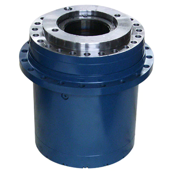
How do gear reducers ensure efficient power transmission and motion control?
Gear reducers play a vital role in ensuring efficient power transmission and precise motion control in various industrial applications. They achieve this through the following mechanisms:
- 1. Speed Reduction/Increase: Gear reducers allow you to adjust the speed between the input and output shafts. Speed reduction is essential when the output speed needs to be lower than the input speed, while speed increase is used when the opposite is required.
- 2. Torque Amplification: By altering the gear ratio, gear reducers can amplify torque from the input to the output shaft. This enables machinery to handle higher loads and provide the necessary force for various tasks.
- 3. Gear Train Efficiency: Well-designed gear trains within reducers minimize power losses during transmission. Helical and spur gears, for example, offer high efficiency by distributing load and reducing friction.
- 4. Precision Motion Control: Gear reducers provide precise control over rotational motion. This is crucial in applications where accurate positioning, synchronization, or timing is required, such as in robotics, CNC machines, and conveyor systems.
- 5. Backlash Reduction: Some gear reducers are designed to minimize backlash, which is the play between gear teeth. This reduction in play ensures smoother operation, improved accuracy, and better control.
- 6. Load Distribution: Gear reducers distribute the load evenly among multiple gear teeth, reducing wear and extending the lifespan of the components.
- 7. Shock Absorption: In applications where sudden starts, stops, or changes in direction occur, gear reducers help absorb and dampen shocks, protecting the machinery and ensuring reliable operation.
- 8. Compact Design: Gear reducers provide a compact solution for achieving specific speed and torque requirements, allowing for space-saving integration into machinery.
By combining these principles, gear reducers facilitate the efficient and controlled transfer of power, enabling machinery to perform tasks accurately, reliably, and with the required force, making them essential components in a wide range of industries.

Are there variations in gear reducer designs for specific tasks and applications?
Yes, gear reducer designs vary widely to suit specific tasks and applications across various industries. Manufacturers offer a range of gear reducer types and configurations to accommodate different requirements, including:
- Helical Gear Reducers: These are versatile and provide smooth and efficient torque transmission. They are commonly used in applications requiring high precision and moderate speed reduction, such as conveyors, mixers, and agitators.
- Bevel Gear Reducers: These are ideal for transmitting power between intersecting shafts. They are often used in heavy machinery, printing presses, and automotive applications.
- Worm Gear Reducers: These provide compact solutions and are suitable for applications with higher speed reduction requirements, such as conveyor systems, winches, and elevators.
- Planetary Gear Reducers: These offer high torque density and are used in applications demanding precise control, such as robotics, aerospace, and heavy-duty machinery.
- Parallel Shaft Gear Reducers: Commonly used in industrial machinery, these reducers are designed for high torque and reliability.
- Right-Angle Gear Reducers: These are used when space limitations require a change in shaft direction, commonly found in packaging equipment and conveyors.
Each type of gear reducer has unique features and benefits that make it suitable for specific tasks. Manufacturers often provide customization options to tailor gear reducers to the precise requirements of an application, including gear ratios, mounting options, and input/output configurations.
Therefore, the variation in gear reducer designs allows industries to select the most appropriate type based on factors such as torque, speed, space constraints, precision, and environmental conditions.


editor by CX 2023-12-08
China Best Sales Aluminum Low Pressure Casting Transmission Housing Gearbox manufacturer
Product Description
PRODUCT INFORMATION
| Item Name | Aluminum Low Pressure Casting Transmission Housing Gearbox |
| General Products Application/Service Area |
Metal Parts Solution for Vehicle, Agriculture machine, Construction Machine, transportation equipment, Agriculture machine metal Parts, etc. |
| Main blank Process for Aluminum Casting | Die Casting, Permanent Molding /Gravity Casting, Low Pressure Casting, . |
| Blanks Tolerance -Casting Tolerance | CT4-6 for Permanent Molding, Die Casting, |
| Applicable Material for casting | A356.0/ZL101,GAlSi7Mg (3.2371.61)/AlSi7Mg/ Or according to customer requirements |
| Casting Blank Size /Dimensions | 2 mm-1500mm / 0.08inch-60inch , or according to customer requirements |
| Casting Blank Weight | Range from 0.01kg-50kg |
| Applicable Machining Process | CNC Machining/ Lathing/ Milling/ Turning/ Boring/ Drilling/ Tapping/ Broaching/Reaming /Grinding/Honing and etc. |
| Machining Tolerance | From 0.005mm-0.01mm-0.1mm |
| Machined Surface Quality | Ra 0.8-Ra3.2 according to customer requirement |
| Applicable Heat Treatment | T5~T6 |
| Applicable Finish Surface Treatment | Shot/sand blast, polishing, Primer Painting , Powder coating, ED- Coating, Finish Painting, Anodize (White or Black Color) |
| MOQ | For aluminum casting : 200pcs For Machining: 50pcs |
| Lead Time | 45days from the receipt date of deposit for Transmission Housing Gearbox |
Products shown here are made to the requirements of specific customers and are illustrative of the types of manufacturing capabilities available within CHINAMFG group of companies.
Please send us your detailed drawing/ sample/requirements for us offering a reasonable quotation to you and we will trying our best to make the goods in good quality and delivery in time .
MATECH policy is that none of these products will be sold to 3rd parties without written consent of the customers to whom the tooling, design and specifications belong.
Production Progress
Mold Design:
For Low pressure casting/Gravity casting, the mold is made of metal materials. In this process, we asked our engineers to make the mold size slightly larger than the finished product, and the difference is called the shrinkage allowance. The purpose of this is to melt the metal into the mold to ensure that the molten metal solidifies and shrinks, thereby preventing voids in the casting process.
Core Making:
The core is formed by casting resin sand into a mold to form a casting of the inner surface. Therefore, the gap between the core and the mold eventually becomes a casting.
Casting Producing:
A mold is required during the smelting process. Molding typically involves the support frame of the mold, which is pulled out to separate during the casting process, where the previously placed core melts in the mold and then closes the die opening.
Cleaning & Machining:
The purpose of cleaning is to remove sand, sand and excess metal in the casting. Welding, sand removal can improve the appearance
of the casting surface by burning the sand and the scale is removed to improve the appearance of the surface of the casting.Excess metal and other risers are removed. A step further by welding and grinding. Some castings are subject to special post-processing requirements such as heat treatment, shaping, anti-rust treatment, roughing, etc.
Finally, Checking the defects and comprehensive quality finishing, before processing, and then re-processing, according to the requirements of different customers, we can do heat treatment, surface treatment, additional inspection and so on.
Process Advantages
* Competitive price with high quality
* Equal in quality,our mold price is 30% lower,and a discount for a big order is certainly valid,because WT mold is an original manufacturer,according to different requirement,our experience technicians can provide reasonable design and advise suitable materialto save cost,while keeping high quality,they can also help to optimize the structure of products if needed.
* Knowledgeable and high precision
* We are familiar with DME HASCO and other standards,we can make molds for vehicle parts with high tolerance requirements
* Stringent quality system
* very process is strictly controlled to prevent problems before they arise.
* Planned Delivery
* Reasonable plHangZhou, perfect designs and low error rate ensure us to proceed as planned.
Application
To satisfy different mechanical and functional requirements from our customers we are making a big range of metal products for our clients on base of different blanks solutions and technologies. These blanks solutions and technologies include processes of Iron Casting, Steel Casting, Stainless Steel Casting, Aluminum Casting and Forging.
Technical Support:
ZheJiang Matech is professional at independent development and design. Our engineers are skilled at AUTO CAD, PRO ENGINEER, SOLID WORKS and other 2D & 3D softwares. We are able to design, develop,produce and deliver your PO according to your drawings, samples or just an idea. Dural control of standard products and OEM products.
Quality Control:
1) Checking the raw material after they reach our factory——- Incoming quality control ( IQC)
2) Checking the details before the production line operated
3) Have full inspection and routing inspection during mass production—In process quality control(IPQC)
4) Checking the goods after they are finished—- Final quality control(FQC)
5) Checking the goods after they are finished—–Outgoing quality control(OQC)
Send Inquiry>>>
Our Factory
ZheJiang Matech Machinery Manufacturer Co., Ltd.
–Branch of Matech Industry ltd.
We specialize in Metal Parts Solution for Vehicle, Agriculture machine, Construction Machine, transportation equipment, Valve and Pump system etc.
With keeping manufacturing process design, quality plHangZhou, key manufacturing processes and final quality control in house we are mastering key competence to supply quality mechanical parts and assembly to our customers for both Chinese and Export Market .
To satisfy different mechanical and functional requirements from our customers we are making a big range of metal products for our clients on base of different blanks solutions and technologies. These blanks solutions and technologies include processes of Iron Casting, Steel Casting, Stainless Steel Casting, Aluminum Casting and Forging.
During the early involvement of the customer’s design process we are giving professional input to our customers in terms of process feasibility, cost reduction and function approach. You are welcome to contact us for technical enquiry and business cooperation.
Our Certificate
Quality Control
1) Checking the raw material after they reach our factory——- Incoming quality control ( IQC)
2) Checking the details before the production line operated
3) Have full inspection and routing inspection during mass production—In process quality control(IPQC)
4) Checking the goods after they are finished—- Final quality control(FQC)
5) Checking the goods after they are finished—–Outgoing quality control(OQC)
Our Customer
Why Choose Us
1. With more than 20 years in Aluminum casting;
2. Have 4 casting types;
3. From Casting to Finished surface, Owned casting,polishing and plating workshops, We can offer Good quality and strict delivery time.
4. With samples and order: We can offer dimension report, Chemical composition and Mechanical properties
5. Control material with spectral and thermal analysis equipment (density and processing)
6. Spectral analysis of raw material and liquid melt, batch before casting.
Thank you to browse our online showroom. If you want to know more about our factory, pls visit our website .
And then email us your inquiry today, we will send you price list in 48 hours.
Our Team
Our Package
Inner Packing →Strong & waterproof plastic big is packed inside, to keep the product in safe condition.Or as customer requests.
Outer Packing →Multilayer wooden box with strong bandages, used for standard export package. Or customized as per customer’s requirements.
FAQ
1Q: Are you trading company or manufacturer?
A: We are factory, so we can provide competitive price for you.
2Q: What kind of service can you provide?
A: Our company (Runze) can provide OEM sheet metal fabrication, CNC machining and manufacturing service.
3Q: What’s kinds of information you need for a quote?
A: In order to quote for you earlier, please provide us the following information together with your inquiry.
1. Detailed drawings (STEP, CAD, CHINAMFG Works, PROE, DXF and PDF)
2. Material requirement (SUS, SPCC, SECC, SGCC, Copper, AL, ETC.)
3. Surface treatment (powder coating, sand blasting, planting, polishing, oxidization, brushing, etc.)
4. Quantity (per order/ per month/ annual)
5. Any special demands or requirements, such as packing, labels, delivery, etc.
4Q: What shall we do if we do not have drawings?
A: Please send your sample to our factory, then we can copy or provide you better solutions. Please send us pictures or drafts with dimensions (Thickness, Length, Height, Width), CAD or 3D file will be made for you if placed order.
5Q: What makes you different from others?
A: 1. Our Excellent Service
We will submit the quotation in 48 hours if getting detailed information during working days.
2. Our quick manufacturing time
For Normal orders, we will promise to produce within 3 to 4 weeks.
As a factory, we can ensure the delivery time according to the formal contract.
6Q: Is it possible to know how are my products going on without visiting your company?
A: We will offer a detailed production schedule and send weekly reports with photos or videos which show the machining progress.
7Q: Can I have a trial order or samples only for several pieces?
A: As the product is customized and need to be produced, we will charge sample cost, but if the sample is not more expensive, we will refund the sample cost after you placed mass orders.
8Q: Why there is tooling cost?
A: It’s mold cost. Indispensable production process. Only need to pay for first order, and we will bear maintenance cost of mold damage.
9Q: What is your terms of payment?
A: Payment of sample order ≤ 1000USD, 100% T/T full payment.
Payment of tooling or batch order ≥ 5000USD, 70% T/T in advance, balance before shipment.
10Q: What’s your after-sale service?
A: If there is quality problem, please provide photos or test report, we will replace defective goods or return funds.
You are welcome to contact us for technical enquiry and business cooperation!
| Application: | Electric Cars, Machinery, Agricultural Machinery |
|---|---|
| Function: | Distribution Power, Clutch, Change Drive Direction, Speed Changing |
| Layout: | Cycloidal |
| Samples: |
US$ 5.2/kg
1 kg(Min.Order) | Order Sample Customized according to product drawings
|
|---|
| Customization: |
Available
| Customized Request |
|---|
.shipping-cost-tm .tm-status-off{background: none;padding:0;color: #1470cc}
|
Shipping Cost:
Estimated freight per unit. |
about shipping cost and estimated delivery time. |
|---|
| Payment Method: |
|
|---|---|
|
Initial Payment Full Payment |
| Currency: | US$ |
|---|
| Return&refunds: | You can apply for a refund up to 30 days after receipt of the products. |
|---|
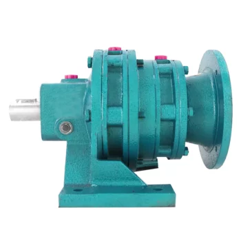
Efficiency of Cycloidal Gearboxes in Power Transmission
Cycloidal gearboxes offer relatively high power transmission efficiency compared to other types of gearboxes. The efficiency of a cycloidal gearbox depends on various factors, including the design, quality of components, lubrication, and load conditions.
Typically, the power transmission efficiency of a cycloidal gearbox ranges from 85% to 95%. However, this can vary based on several factors:
- Number of Reduction Stages: Multi-stage cycloidal gearboxes may experience slightly lower efficiency due to multiple gear meshing interactions.
- Quality and Design: Well-designed and precision-manufactured cycloidal gearboxes tend to exhibit higher efficiency.
- Lubrication: Proper lubrication is crucial for reducing friction and enhancing efficiency. Insufficient or deteriorated lubrication can lead to efficiency losses.
- Load Conditions: Higher loads and torque levels can lead to higher friction and lower efficiency. Properly matching the gearbox to the application is essential.
Despite minor efficiency losses compared to some other gearbox types, the benefits of compactness, high torque density, and precise motion control often outweigh the efficiency considerations in many applications.
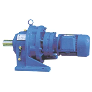
Use of Cycloidal Gearboxes in Precision Applications
Cycloidal gearboxes are well-suited for precision applications due to their unique design and capabilities. Here’s why they are used in precision settings:
- High Positional Accuracy: Cycloidal gearboxes offer high positional accuracy, making them suitable for applications that require precise positioning and movement.
- Backlash Reduction: The design of cycloidal gearboxes minimizes backlash, ensuring that there is minimal play between gears. This is crucial for maintaining accuracy in precision applications.
- Smooth and Controlled Motion: Cycloidal gearboxes provide smooth and controlled motion with minimal vibration, which is essential for delicate operations and precision machinery.
- Compact Design: Their compact design allows cycloidal gearboxes to be integrated into tight spaces without sacrificing performance. This is especially valuable in applications where space is limited.
- Repeatable Performance: Cycloidal gearboxes offer consistent and repeatable performance, which is vital for maintaining precision over multiple cycles.
- Low Backlash: The low backlash characteristic of cycloidal gearboxes ensures that there is minimal lost motion, contributing to their precision performance.
- High Torque Density: Despite their compact size, cycloidal gearboxes can handle high torque loads, making them suitable for applications that require both precision and power.
- Reduced Wear: The rolling contact design of cycloidal gears reduces wear and extends the lifespan of the gearbox, which is crucial for precision applications that demand consistent performance over time.
Overall, cycloidal gearboxes are a reliable choice for precision applications that require accurate positioning, controlled motion, and consistent performance.
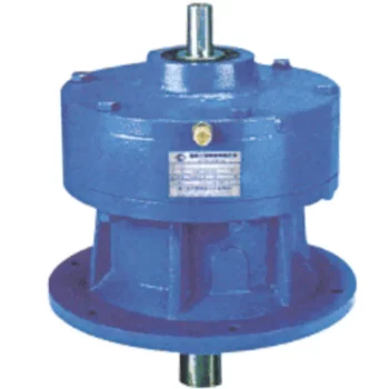
How Does a Cycloidal Gearbox Work?
A cycloidal gearbox operates on the principle of cycloidal motion to transmit rotational power. It consists of a set of components that work together to achieve smooth and efficient motion transmission:
- High-Speed Input Shaft: The gearbox is connected to a high-speed input shaft, typically driven by an electric motor or another power source.
- Cycloidal Pins or Rollers: Surrounding the input shaft are a series of cycloidal pins or rollers arranged in a circular pattern. These pins interact with the lobed profiles of the outer stationary ring.
- Outer Stationary Ring: The outer ring remains stationary and contains lobed profiles. The lobes are designed in a way that allows them to engage with the cycloidal pins as they rotate.
- Motion Transmission: As the input shaft rotates, it causes the cycloidal pins to move along the circular path. The interaction between the cycloidal pins and the lobed profiles of the outer ring results in a unique motion known as epicycloidal or hypocycloidal motion.
This motion generates torque that is transferred from the input shaft to the output shaft of the gearbox. The main advantage of a cycloidal gearbox is its ability to provide high torque output in a compact design. The multiple points of contact between the pins and the lobes distribute the load, enhancing the gearbox’s load-carrying capacity.
Cycloidal gearboxes are known for their smooth and controlled motion, making them suitable for applications requiring precise positioning and high torque capabilities, such as robotics, automation, and industrial machinery.


editor by CX 2023-11-14
China Custom Transmission Worm Gear Motor cycloidal gearbox manufacturers
Product Description
Detailed Photos
Product Description
Components:
1. Housing: Die-cast Aluminium Alloy Gearbox (RV571~RV090)Cast Iron Gearbox (RV110~RV150)
2. Worm Wheel: Wearable Tin Bronze Alloy, Aluminum Bronze Alloy
3. Worm Shaft: 20Cr Steel, carburizing, quenching, grinding, surface hardness 56-62HRC, 0.3-0.5mm remaining carburized
layer after precise grinding
4. Input Configurations:
Equipped with Electric Motors (AC Motor, Brake Motor, DC Motor, Servo Motor)
IEC-normalized Motor Flange
Solid Shaft Input
Worm Shaft Tail Extension Input
5. Output Configurations:
Keyed Hollow Shaft Output
Hollow Shaft with Output Flange
Plug-in CZPT Shaft Output
Models:
Hollow Shaft Input with IEC-normalized Motor Flange
RV571~RV150
Solid Shaft Input
RV571~RV150
Product Parameters
Technical Data
|
Models |
Rated Power |
Rated |
Input Hole |
Input Shaft |
Output Hole |
Output Shaft |
|
RV571 |
0.06KW~0.12KW |
5~60 |
Φ9 |
Φ9 |
Φ11 |
Φ11 |
|
RV030 |
0.06KW~0.25KW |
5~80 |
Φ9(Φ11) |
Φ9 |
Φ14 |
Φ14 |
|
RV040 |
0.09KW~0.55KW |
5~100 |
Φ9(Φ11,Φ14) |
Φ11 |
Φ18(Φ19) |
Φ18 |
|
RV050 |
0.12KW~1.5KW |
5~100 |
Φ11(Φ14,Φ19) |
Φ14 |
Φ25(Φ24) |
Φ25 |
|
RV063 |
0.18KW~2.2KW |
7.5~100 |
Φ14(Φ19,Φ24) |
Φ19 |
Φ25(Φ28) |
Φ25 |
|
RV075 |
0.25KW~4.0KW |
7.5~100 |
Φ14(Φ19,Φ24,Φ28) |
Φ24 |
Φ28(Φ35) |
Φ28 |
|
RV090 |
0.37KW~4.0KW |
7.5~100 |
Φ19(Φ24,Φ28) |
Φ24 |
Φ35(Φ38) |
Φ35 |
|
RV110 |
0.55KW~7.5KW |
7.5~100 |
Φ19(Φ24,Φ28,Φ38) |
Φ28 |
Φ42 |
Φ42 |
|
RV130 |
0.75KW~7.5KW |
7.5~100 |
Φ24(Φ28,Φ38) |
Φ30 |
Φ45 |
Φ45 |
|
RV150 |
2.2KW~15KW |
7.5~100 |
Φ28(Φ38,Φ42) |
Φ35 |
Φ50 |
Φ50 |
Ratio: 5, 7.5, 10, 15, 20, 25, 30, 40, 50, 60, 80, 100
Installation:
Flange Mounted
Foot Mounted
Torque Arm Mounted
Lubrication:
Grease Lubrication
Oil-bath and Splash Lubrication
Cooling:
Natural Cooling
Certifications
Company Profile
Xihu (West Lake) Dis.ng Transmission Equipment Co., Ltd. located HangZhou city, ZHangZhoug, as 1 professional manufacturer
and exporter of cycloidal pin wheel reducer,worm reducer, gear reducer, gearbox , AC motor and relative spare
parts, owns rich experience in this line for many years.
We are 1 direct factory, with advanced production equipment, the strong development team and producing
capacity to offer quality products for customers.
Our products widely served to various industries of Metallurgy, Chemicals, lifting,mining,Petroleum,textile,medicine,wooden etc. Main markets: China, Africa,Australia,Vietnam, Turkey,
Japan, Korea, Philippines…
Welcome to ask us any questions, good offer always for you for long term business.
FAQ
Q: Are you trading company or manufacturer?
A: We are factory.
Q: How long is your delivery time?
A: Generally it is 5-10 days if the goods are in stock. or it is 15-20 days if the goods are not in stock.
Q: Can we buy 1 pc of each item for quality testing?
A: Yes, we are glad to accept trial order for quality testing.
Q:How to choose a gearbox which meets your requirement?
A:You can refer to our catalogue to choose the gearbox or we can help to choose when you provide
the technical information of required output torque, output speed and motor parameter etc.
Q: What information shall we give before placing a purchase order?
A:a) Type of the gearbox, ratio, input and output type, input flange, mounting position, and motor informationetc.
b) Housing color.
c) Purchase quantity.
d) Other special requirements.
| Application: | Motor, Machinery, Marine, Agricultural Machinery |
|---|---|
| Hardness: | Hardened Tooth Surface |
| Installation: | Vertical Type |
| Layout: | Coaxial |
| Gear Shape: | Worm Gear |
| Step: | Single-Step |
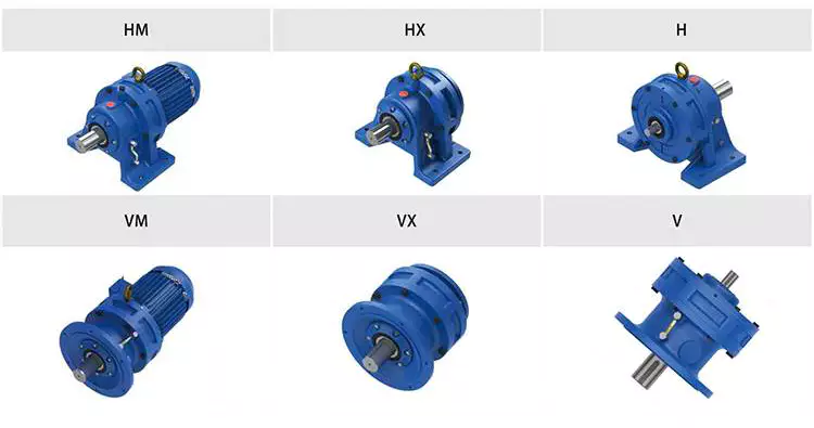
How to Use a Cyclone Gearbox
Often, a cycloidal gearbox is used in order to achieve a torque transfer from a motor or pump. This type of gearbox is often a common choice as it has a number of advantages over a regular gearbox. Its main advantage is that it is easy to make, which means that it can be incorporated into a variety of applications. However, if you want to use a cycloidal gearbox, there are a few things that you need to know. These include the operation principle, the structure and the dynamic and inertial effects that come with it.
Dynamic and inertial effects
Several studies have been carried out on the static and dynamic properties of cycloidal gears. The study of these effects is beneficial in assisting optimal design of cycloidal speed reducers.
In this paper, the dynamic and inertial effects of a two-stage cycloidal speed reducer have been investigated using the CZPT program package. Moreover, a new model for cycloidal reducers based on non-linear contact dynamics has been developed. The new model aims to predict several operational conditions.
The normal excitation contact force for the cycloid discs of the first and second stage is very similar. However, the total deformation at the contact point is different. This effect is mainly due to the system’s own oscillations. The cycloid discs of the second stage turn around the ring gear roller with a 180deg angle. This angle is a significant contributor to the torque loads. The total excitation force on the cycloid discs of first and second stage is 1848 N and 2068.7 N, respectively.
In order to analyze the contact stress, different gear profiles were investigated. The mesh density was considered as an important design criterion. It was found that a bigger hole reduces the material content of the cycloidal disc and results in more stresses.
Moreover, it is possible to reduce the contact forces in a more efficient manner by changing the geometric parameters. This can be done by mesh refinement along the disc width. The cycloidal disc has the greatest influence on the output results.
The efficiency of a cycloidal drive increases with the increase in load. The efficiency of a cycloidal reducer also depends on the eccentricity of the input shaft and the cycloidal plate. The efficiency curve for small loads is linear. However, for the larger loads, the efficiency curve becomes more non-linear. This is because the stiffness of the cycloid reducer increases as the load increases.
Structure
Despite the fact that it looks like a complicated engineering puzzle, the construction of a cycloidal gearbox is actually quite simple. The key elements are the base, the load plate and the thrust bearing. All these elements work together to create a stable, compact gearbox.
The base is a circular section with several cylindrical pins around its outer edge. The pins are fixed on a fixed ring that holds them in a circular path. The ring serves as a reference circle. The circle’s size is approximately 5mm in diameter.
The load plate is a series of threaded screw holes. These are arranged 15mm away from the center. These are used to anchor external structures. The load plate must be rotated around the X and Y axis.
The thrust bearing is placed on top of the load plate. The bearing is made of an internal diameter of 35mm and an external diameter of 52mm. It is used to allow rotation around the Z axis.
The cycloidal disc is the centerpiece of the cycloidal gearbox. The disc has holes for the pins that drive the output shaft. The holes are larger than those used in output roller pins. The disc also has a reduced eccentricity.
The pins are attached to the cycloidal disc by rolling pins. The pins are made of a material that provides mechanical support for the drive during high-torque situations. The pins have a 9mm external diameter. The disc has a number of lobes and is rotated by one lobe per shaft revolution.
The cycloidal gearbox also has a top cover that helps keep the components together. The cover has a pocket for tools. The top cover also has threads that screw into the casing.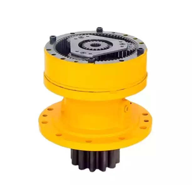
Operation principle
Among many types of gear transmissions, cycloidal gearboxes are used in heavy machinery and multi-axis robots. They are highly effective, compact and capable of high ratios. In addition, they have an overload capability.
Cycloid disks are driven by eccentric shafts that rotate around fixed ring pins. Roller pins of the pin disc engage with holes in the cycloidal disc. These roller pins drive the pin disc and the pin disc transfers the motion to the output shaft.
Unlike conventional gear drives, cycloidal drives have low backlash and high torsional stiffness. They are ideally suited to heavy loads and all drive technologies. The lower mass and compact design of the cycloidal disk also contributes to its high efficiency and positioning accuracy.
The cycloidal disc plays a central role in the gearbox kinematics. It rotates around a fixed ring in a circle. When the disc is pushed against the ring gear, the pins engage with the disc and the roller pins rotate around the pins. This rotating motion generates vibration, which travels through the driven shafts.
Cycloid discs are typically designed with a short cycloid, so that the eccentricity is minimized. This reduces unbalance forces at high speeds. Ideally, the number of lobes on the cycloid is smaller than the number of surrounding pins. This reduces the amount of Hertzian contact stress.
Unlike planetary gears, cycloidal gears have high accuracy and are capable of withstanding shock loads. They also experience low friction and less wear on tooth flanks. They also have higher efficiency and load capacity.
Cycloid gears are generally more difficult to manufacture than involute gears. Cycloid gears are not suitable for stacking gear stages. They require extreme accuracy for manufacturing. However, their smaller size and low backlash, high torsional stiffness, and low vibration make them ideal for use in heavy machines.
Involute gear tooth profile
Almost all gears are manufactured with an involute gear tooth profile. Cycloid gears are also produced with this profile. Compared with involute gears, cycloid gears are stronger and can transmit more power. However, they can also be more difficult to manufacture. This makes them costlier.
The involute gear tooth profile is a smooth curve. It is derived from the involute curve of a circle. A tangent to the base circle is the normal at any point of an involute.
This curve has properties that allow the involute gear teeth to transfer motion in perpendicular direction. It is also the path traced by the end of the string unwrapping from a cylinder.
An involute profile has the advantage of being easy to manufacture. It also allows for smooth meshing despite misalignment of the centre distance. This profile is also preferred over a cycloid tooth profile, but it is not the best in every regard.
Cycloid gear teeth are also made of two curves. Unlike involute teeth, cycloid gear teeth have a consistent radius. Cycloid gears are less likely to produce noise. But they are also more expensive to manufacture.
Involute teeth are easier to manufacture because they have only one curve. Cycloid gears can also be made with a rack type cutter. This makes them cheaper to manufacture. However, they require an expert design. They can also be manufactured with a gear shaper that includes a pinion cutter.
The tooth profiles that satisfy the law of gear-tooth action are sometimes called conjugate profiles. The involute profile is the most common of these. It allows for constant torque transmission.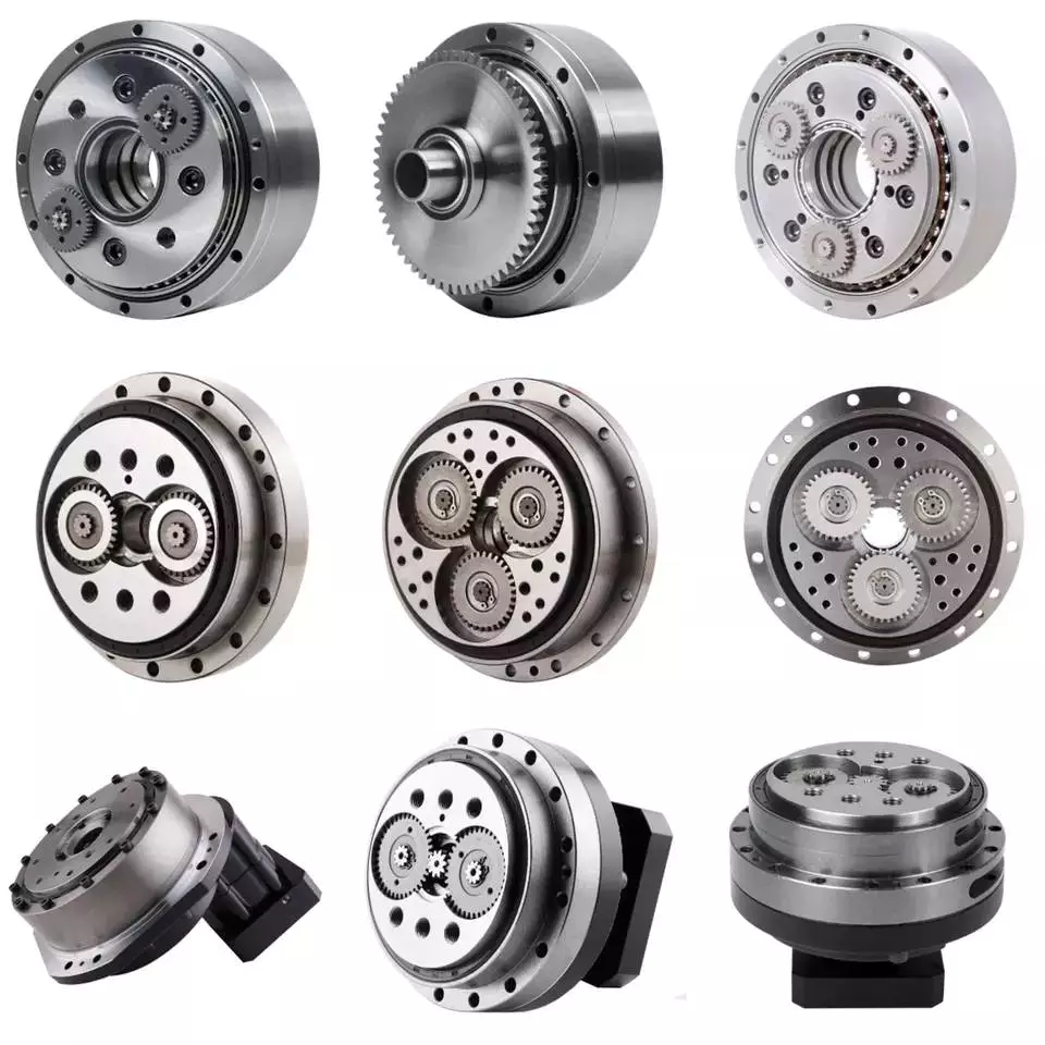
Backlash
Typically, cycloidal drives provide a high ratio of transmission with no backlash. This is because the cycloid disc is driven by an eccentric shaft. During rotation, the cycloid disc rotates around a fixed ring. This ring also rotates independently of the center of gravity.
The cycloid disc is typically shortened to reduce the eccentricity. This helps to minimize the unbalance forces that may occur at high speeds. The cycloid also offers a larger gear ratio than traditional gears. This provides a better positional accuracy.
Cycloid drives also have a high torsional stiffness. This provides greater torsional resilience and shock load capabilities. This is important for a number of reasons, such as in heavy-duty applications.
Cycloid drives also have lower mass. These benefits make them ideally suited for all drive technologies. The design also allows for higher torsional stiffness and service life. These drives also have a much smaller profile.
Cycloid drives are also used to reduce speed. Because of the high torsional stiffness of the cycloid, they also have high positioning accuracy.
Cycloid drives are well-suited to a variety of applications, including electric motors, generators, and pump motors. They are also highly resistant to shock loads, which is important in a variety of applications. This design is ideal for applications that require a large transmission ratio in a compact design.
Cycloid drives also have the advantage of minimizing the clearance between the mating components. This helps to eliminate interference and ensure a positive fit. This is particularly important in gearboxes. It also allows for the use of a load cell and potentiometer to determine the backlash of the gearbox.

editor by CX 2023-11-13