Product Description
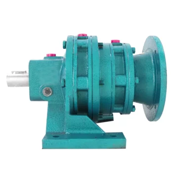
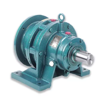
High Torque Cast Iron Gearbox Gear Reducer Motor speed reducer for industrial equipment components
< ABOUT TILI
HangZhou Tili Reducer Co., Ltd. is located in CHINAMFG Industrial Concentration Zone, Zou District, Xihu (West Lake) Dis. District, HangZhou, China. It is a professional company that produces reducers. The company specializes in the production of various reducer products, including DJYG series high torque series extruder gearboxes, CHINAMFG series single screw extruder gearboxes, SZ, SZL series conical twin-screw extruder gearboxes, and more. In addition, the company also produces R, K, F, S series helical gear reducers, B/X series cycloidal pinwheel reducers, planetary reducers, etc. The company not only has professional capabilities in the design and manufacturing of hard tooth surface gearboxes and cycloidal pinwheel gearboxes, but also its products have entered various provinces, cities, and autonomous regions across the country. Some of its products are exported to foreign countries, mainly supporting the fields of plastics, rubber, metallurgy and mining, petrochemicals, lifting and transportation, light industry and food.
HangZhou Taili Reducer Co., Ltd. has been committed to providing customers with high-quality hard tooth extrusion reducers for more than 20 years since its establishment. The product quality has been unanimously recognized by domestic and foreign customers through market validation. The company has strong technological and business management capabilities, and has introduced top processing equipment from Germany and Switzerland. The product quality is reliable, and the after-sales service is complete. It can provide users with special designs to meet their requirements.
R series helical gear units
product/xteUysJGvQVq/China-R-Series-Foot-Mounted-Coaxial-Gearbox-with-Inline-Standard-Motor.html
R series:Small size, light weight, large transmission torque, superior performance, stable operation, low noise, durable, can be installed in a variety of ways, can be matched with different types of motors, a wide range of applications. sewage treatment, chemical industry, pharmacy and other industries.
K series helical-bevel gear units
product/CAepOqywMEhH/China-K-Series-Hardened-Tooth-Surface-Helical-Bevel-Foot-Mounted-Gearbox-with-Inline-Standard-Motor.html
K series gearbox is 1 kind of Helical Bevel type gearbox ,it is designed based on modularization , which bring many difference kinds of combinations ,mounting types ,and structure designs .The detail classification of ratio can meet various of working condition .High Transmission efficiency ,low energy consumption, superior performance .
S series helical-worm gear units
product/laXYVUyhOxWn/China-S-Series-Foot-Mounted-Helical-Worm-Gearbox-with-Solid-Shaft-with-Inline-Standard-Motor.html
S series: right-angle speed reduction gearing composed by helical gears, worms, and gears, optimized and designed according to international standard.High precision, high efficiency, fine classification in transmission ratio, wide range, large transmission torque, reliable performance, low noise, flexible installation, and convenient use and maintenance.
F series parallel-shaft helical gear units
product/wTPpMGtcvQVl/China-F-Series-Foot-Mounted-Parallel-Shaft-Gearbox-with-Inline-Standard-Motor.html
F series speed gear reducer is 1 kind of parallel shaft helical gear reducer , which consist of 2 or 3 stages helical gears (relate to gear ratio) in the same case . The hard tooth surface gear use the high quality alloy steel ,the process of carburizing and quenching, grinding .
| Product Name | High Torque Cast Iron Gearbox Gear Reducer Motor speed reducer for industrial equipment components |
| Power | 0.12KW~160KW |
| Torque | 1.4N · m ~ 36600N · m |
| Output speed | 0.06 ~ 1090r/min |
| Gear material | 20CrMnTi alloy steel |
| Gear Processing | Grinding finish by HOFLER Grinding Machines |
| Noise Test | Below 65dB |
| Brand of bearings | C&U bearing, ZWZ,LYC, HRB, CHINAMFG ,etc |
| Brand of oil seal | NAK or other brand |
| Temp. rise (MAX) | 40ºC |
| Temp. rise (Oil)(MAX | 50ºC |
| Vibration | ≤20µm |
| Housing hardness | HBS190-240 |
| Surface hardness of gears | HRC58°~62 ° |
| Gear core hardness | HRC33~40 |
| Machining precision of gears | 5 Grade |
| Lubricating oil | GB L-CKC220-460, Shell Omala220-460 |
| Heat treatment | Carburizing, Quenching etc |
| Efficiency | 95%~96% (depends on the transmission stage) |
| Bearing output mode | parallel output |
| Installation type and output mode | Bottom seated type flange type installation, solid,hollow shaft output. |
| Input mode | Direct motor, shaft input and connecting flange input |
| Input Method | Flange input(AM), shaft input(AD), inline AC motor input, or AQA servo motor |
Detailed Photos
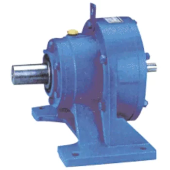
R SERIES
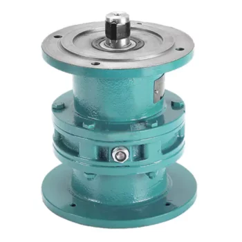
K SERIES
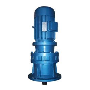
S SERIES
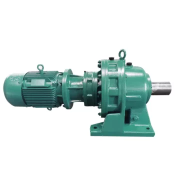
F SERIES
Company Profile
< WORKSHOP
< QUALITY CONTROL
Certifications
Packaging & Shipping
FAQ
Q 1: Are you a trading company or a manufacturer?
A: We are a professional manufacturer specializing in manufacturing various series of reducer.
Q 2:Can you do OEM?
A:Yes, we can. We can do OEM for all the customers .if you want to order NON-STANDERD speed reducers,pls provide Drafts, Dimensions, Pictures and Samples if possible.
Q 3: How long is your warranty?
A: Our Warranty is 12 months under normal circumstances.
Q 4: Do you have inspection procedures for reducer?
A:100% self-inspection before packing.
Q 5: Can I have a visit to your factory before the order?
A: Sure, welcome to visit our factory.
Q 6:How to choose a gearbox? What if I don’t know which gear reducer I need?
A:You can refer to our catalogue to choose the gearbox or we can help to choose when you provide,the technical information of required output torque, output speed and motor parameter etc. Don’t worry, Send as much information as you can, our team will help you find the right 1 you are looking for.
Q 7: What information shall we give before placing a purchase order?
A:a) Type of the gearbox, Size , Transmission Ratio, input and output type, input flange, mounting position, motor information and shaft deflection etc. b)Housing color.c) Purchase quantity. d) Other special requirements
Q 8:What is the payment term?
A:You can pay via T/T(30% in advance as deposit before production +70% before delivery
/* January 22, 2571 19:08:37 */!function(){function s(e,r){var a,o={};try{e&&e.split(“,”).forEach(function(e,t){e&&(a=e.match(/(.*?):(.*)$/))&&1
| Application: | Machinery, Agricultural Machinery, Industrial Automation Equipment, Chemical Industry |
|---|---|
| Function: | Distribution Power, Change Drive Torque, Speed Changing, Speed Reduction |
| Layout: | Coaxial |
| Customization: |
Available
| Customized Request |
|---|
.shipping-cost-tm .tm-status-off{background: none;padding:0;color: #1470cc}
|
Shipping Cost:
Estimated freight per unit. |
about shipping cost and estimated delivery time. |
|---|
| Payment Method: |
|
|---|---|
|
Initial Payment Full Payment |
| Currency: | US$ |
|---|
| Return&refunds: | You can apply for a refund up to 30 days after receipt of the products. |
|---|
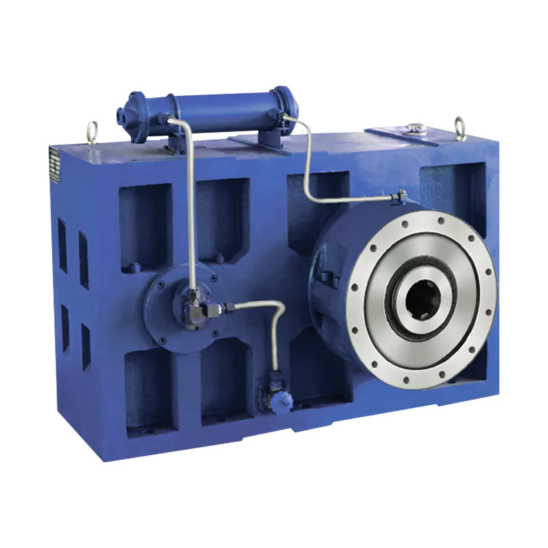
Can you provide real-world examples of products that use gear reducer technology?
Certainly! Gear reducer technology is widely used in various industries and products to enhance performance and efficiency. Here are some real-world examples:
1. Industrial Machinery: Gear reducers are commonly used in manufacturing machinery, such as conveyor systems, material handling equipment, and assembly lines, where they help control speed and torque for precise operations.
2. Wind Turbines: Wind turbines utilize gear reducers to transform the low rotational speed of the wind turbine rotor into the higher speed needed for electricity generation, optimizing energy conversion.
3. Automotive Transmissions: Automobiles use gear reducers as part of their transmissions to optimize power delivery from the engine to the wheels, allowing the vehicle to operate efficiently at different speeds.
4. Robotics: Robotic systems rely on gear reducers to control the movement and articulation of robot arms, enabling precise and controlled motion for various applications.
5. Printing Presses: Gear reducers are integral to printing presses, ensuring accurate and synchronized movement of printing plates, rollers, and paper feed mechanisms.
6. Conveyor Belts: Conveyor systems in industries like mining, agriculture, and logistics use gear reducers to regulate the movement of materials along the conveyor belts.
7. Packaging Machinery: Gear reducers play a crucial role in packaging machines, controlling the speed and movement of packaging materials, filling mechanisms, and sealing components.
8. Cranes and Hoists: Cranes and hoists rely on gear reducers to lift heavy loads with precision and control, ensuring safe and efficient material handling.
9. Pumps and Compressors: Gear reducers are utilized in pumps and compressors to regulate fluid flow and pressure, optimizing energy usage in fluid transportation systems.
10. Agriculture Equipment: Tractors and other agricultural machinery use gear reducers to adjust the speed and power delivery for different tasks, such as plowing, planting, and harvesting.
These examples demonstrate the diverse applications of gear reducer technology across various industries, showcasing their role in enhancing efficiency, control, and performance in a wide range of products and systems.
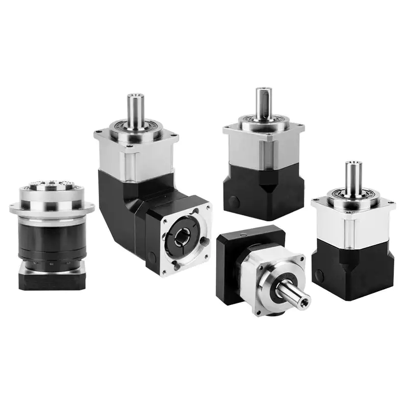
Can gear reducers be used for both speed reduction and speed increase?
Yes, gear reducers can be utilized for both speed reduction and speed increase, depending on their design and arrangement. The functionality to either decrease or increase rotational speed is achieved by altering the arrangement of gears within the gearbox.
1. Speed Reduction: In speed reduction applications, a gear reducer is designed with gears of different sizes. The input shaft connects to a larger gear, while the output shaft is connected to a smaller gear. As the input shaft rotates, the larger gear turns the smaller gear, resulting in a decrease in output speed compared to the input speed. This configuration provides higher torque output at a lower speed, making it suitable for applications that require increased force or torque.
2. Speed Increase: For speed increase, the gear arrangement is reversed. The input shaft connects to a smaller gear, while the output shaft is connected to a larger gear. As the input shaft rotates, the smaller gear drives the larger gear, resulting in an increase in output speed compared to the input speed. However, the torque output is lower than that of speed reduction configurations.
By choosing the appropriate gear ratios and arrangement, gear reducers can be customized to meet specific speed and torque requirements for various industrial applications. It’s important to select the right type of gear reducer and configure it correctly to achieve the desired speed reduction or speed increase.
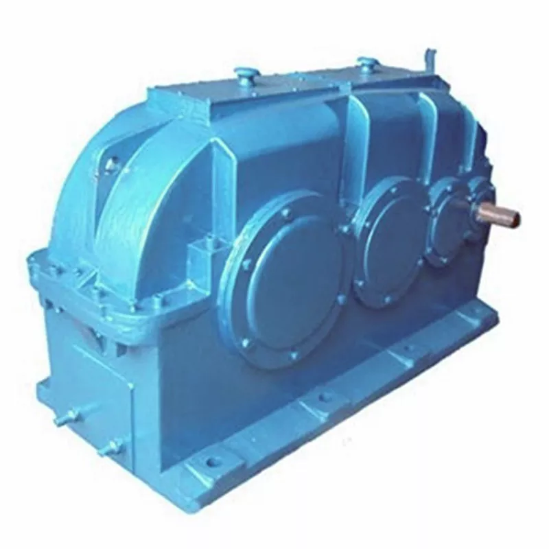
How do gear reducers contribute to speed reduction and torque increase?
Gear reducers play a crucial role in mechanical systems by achieving speed reduction and torque increase through the principle of gear ratios. Here’s how they work:
Gear reducers consist of multiple gears with different sizes, known as gear pairs. These gears are meshed together, and their teeth interlock to transmit motion and power. The gear ratio is determined by the ratio of the number of teeth on the input gear (driver) to the number of teeth on the output gear (driven).
Speed Reduction: When a larger gear (output gear) is driven by a smaller gear (input gear), the output gear rotates at a slower speed than the input gear. This reduction in speed is proportional to the gear ratio. As a result, gear reducers are used to slow down the rotational speed of the output shaft compared to the input shaft.
Torque Increase: The interlocking teeth of gears create a mechanical advantage that allows gear reducers to increase torque output. When the input gear applies a force (torque) to the teeth, it is transmitted to the output gear with greater force due to the leverage provided by the larger diameter of the output gear. The torque increase is inversely proportional to the gear ratio and is essential for applications requiring high torque at lower speeds.
By selecting appropriate gear ratios and arranging gear pairs, gear reducers can achieve various speed reduction and torque multiplication factors, making them essential components in machinery and equipment where precise control of speed and torque is necessary.


editor by CX 2024-05-10
China Best Sales High Torque Robotic Motor Gear Reducer gearbox drive shaft
Product Description
Product Description
HMCG-I Series Harmonic Reducer
Introducing the HMCG-I Series Harmonic Reducer from HangZhou Yijiaang Automation Technology Co., Ltd! Designed for aerospace, robotics, semiconductors, power inspection, and automation equipment.
Experience the Power of Harmonic Gear Transmission
Discover the cutting-edge transmission mode invented by C.W. Musser in 1955. The HMCG-I series utilizes elastic deformation for movement and power transmission, replacing traditional rigid components with flexibility for enhanced functionality.
Unleash the Deceleration Principle
Harness the power of the deceleration principle with the HMCG-I series harmonic reducer. The flexwheel, rigid wheel, and wave generator work together seamlessly for precise and efficient movement transmission.
Product Specifications
Product Name:
Industrial Robot Ultra-Thin Series Hmcg Harmonic Precision Reducer
Applicable Industries: Machinery, Agricultural Machinery, Car, Robot
Hardened Tooth Surface: Yes
Installation Type: Horizontal Type
Upgrade to the future of precision and efficiency today with the HMCG-I series harmonic reducer!
Company Name: HangZhou Yijiaang Automation Technology Co., Ltd
Product Parameters
| Model | Reduction ratio | Rated torque at input 2000r/min |
Permissible CHINAMFG torque at start/stop | Permissible max.value of ave.load torque | instantaneous permissible max.torque | Permssibie max.input rotational speed | Permissible ave.input rotational speed | Backlash (arc sec) | Transmission accuracy(arc sec) |
| Nm | Nm | Nm | Nm | r/min | r/min | ≤ | ≤ | ||
| 14 | 50 | 7 | 23 | 9 | 46 | 8000 | 3500 | 20 | 90 |
| 80 | 10 | 30 | 14 | 51 | 20 | 90 | |||
| 100 | 10 | 36 | 14 | 70 | 10 | 90 | |||
| 17 | 50 | 21 | 44 | 34 | 91 | 7000 | 3500 | 20 | 90 |
| 80 | 29 | 56 | 35 | 113 | 20 | 90 | |||
| 100 | 31 | 70 | 51 | 143 | 10 | 90 | |||
| 20 | 50 | 33 | 73 | 44 | 127 | 6000 | 3500 | 20 | 60 |
| 80 | 44 | 96 | 61 | 165 | 20 | 60 | |||
| 100 | 52 | 107 | 64 | 191 | 10 | 60 | |||
| 120 | 52 | 113 | 64 | 161 | 10 | 60 | |||
| 25 | 50 | 51 | 127 | 72 | 242 | 5500 | 3500 | 20 | 60 |
| 80 | 82 | 178 | 113 | 332 | 20 | 60 | |||
| 100 | 87 | 204 | 140 | 369 | 10 | 60 | |||
| 120 | 87 | 217 | 140 | 395 | 10 | 60 | |||
| 32 | 50 | 99 | 281 | 140 | 497 | 4500 | 3500 | 20 | 60 |
| 80 | 153 | 395 | 217 | 738 | 10 | 60 | |||
| 100 | 178 | 433 | 281 | 841 | 10 | 60 | |||
| 120 | 178 | 459 | 281 | 892 | 10 | 60 | |||
| 40 | 50 | 178 | 523 | 255 | 892 | 4000 | 3000 | 10 | 60 |
| 80 | 268 | 675 | 369 | 1270 | 10 | 60 | |||
| 100 | 345 | 738 | 484 | 1400 | 10 | 60 | |||
| 120 | 382 | 802 | 586 | 1530 | 10 | 60 |
Company Profile
Industrial Robot Ultra-Thin Series Hmcg Harmonic Precision Reducer
Introducing the Industrial Robot Ultra-Thin Series Hmcg Harmonic Precision Reducer
Revolutionize your machinery with the cutting-edge technology of the Industrial Robot Ultra-Thin Series Hmcg Harmonic Precision Reducer from HangZhou Yijiaang Automation Technology Co., Ltd. This product is designed to take your transmission components to the next level, providing unmatched performance and reliability.
Featuring a hardened tooth surface, this precision reducer ensures durability and longevity, making it perfect for a wide range of applications including machinery, agricultural machinery, cars, and robots. Its horizontal installation design allows for easy integration into your existing systems, saving you time and effort.
Experience the power of this ultra-thin harmonic reducer, boasting exceptional speed reduction capabilities. Its advanced gearbox technology guarantees smooth and precise operation, allowing for seamless performance in CNC machine tools, packaging machinery, printing machinery, automation equipment, joint robots, medical equipment, AGV, and more.
At HangZhou Yijiaang Automation Technology Co., Ltd, we are committed to providing you with the highest quality products and services. Our team of experts is dedicated to technological innovation and customer satisfaction, ensuring that you receive the best possible experience.
Enhance your machinery with the Industrial Robot Ultra-Thin Series Hmcg Harmonic Precision Reducer and achieve new levels of efficiency and productivity. Contact us today!
Detailed Photos
FAQ
/* January 22, 2571 19:08:37 */!function(){function s(e,r){var a,o={};try{e&&e.split(“,”).forEach(function(e,t){e&&(a=e.match(/(.*?):(.*)$/))&&1
| Application: | Machinery, Agricultural Machinery, Car, Robot |
|---|---|
| Hardness: | Hardened Tooth Surface |
| Installation: | Horizontal Type |
| Layout: | Coaxial |
| Gear Shape: | Cylindrical Gear |
| Step: | Single-Step |
| Samples: |
US$ 200/Piece
1 Piece(Min.Order) | |
|---|
| Customization: |
Available
| Customized Request |
|---|
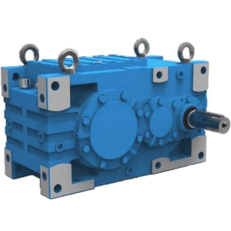
How do gear reducers contribute to energy efficiency in machinery and equipment?
Gear reducers play a significant role in enhancing energy efficiency in various machinery and equipment. Here’s how they contribute:
1. Speed Reduction: Gear reducers are commonly used to reduce the speed of the input shaft, allowing the motor to operate at a higher speed where it’s most efficient. This speed reduction helps match the motor’s optimal operating range, reducing energy consumption.
2. Torque Increase: Gear reducers can increase torque output while decreasing speed, enabling machinery to handle higher loads without the need for a larger, more energy-intensive motor.
3. Matching Load Requirements: By adjusting gear ratios, gear reducers ensure that the machinery’s output speed and torque match the load requirements. This prevents the motor from operating at unnecessary high speeds, saving energy.
4. Variable Speed Applications: In applications requiring variable speeds, gear reducers allow for efficient speed control without the need for continuous motor adjustments, improving energy usage.
5. Efficient Power Transmission: Gear reducers efficiently transmit power from the motor to the load, minimizing energy losses due to friction and inefficiencies.
6. Motor Downsizing: Gear reducers enable the use of smaller, more energy-efficient motors by converting their higher speed, lower torque output into the lower speed, higher torque needed for the application.
7. Decoupling Motor and Load Speeds: In cases where the motor and load speeds are inherently different, gear reducers ensure the motor operates at its most efficient speed while still delivering the required output to the load.
8. Overcoming Inertia: Gear reducers help overcome the inertia of heavy loads, making it easier for motors to start and stop, reducing energy consumption during frequent operation.
9. Precise Control: Gear reducers provide precise control over speed and torque, optimizing the energy consumption of machinery in processes that require accurate adjustments.
10. Regenerative Braking: In some applications, gear reducers can be used to capture and convert kinetic energy back into electrical energy during braking or deceleration, improving overall energy efficiency.
By efficiently managing speed, torque, and power transmission, gear reducers contribute to energy-efficient operation, reducing energy consumption, and minimizing the environmental impact of machinery and equipment.
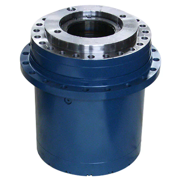
How do gear reducers ensure efficient power transmission and motion control?
Gear reducers play a vital role in ensuring efficient power transmission and precise motion control in various industrial applications. They achieve this through the following mechanisms:
- 1. Speed Reduction/Increase: Gear reducers allow you to adjust the speed between the input and output shafts. Speed reduction is essential when the output speed needs to be lower than the input speed, while speed increase is used when the opposite is required.
- 2. Torque Amplification: By altering the gear ratio, gear reducers can amplify torque from the input to the output shaft. This enables machinery to handle higher loads and provide the necessary force for various tasks.
- 3. Gear Train Efficiency: Well-designed gear trains within reducers minimize power losses during transmission. Helical and spur gears, for example, offer high efficiency by distributing load and reducing friction.
- 4. Precision Motion Control: Gear reducers provide precise control over rotational motion. This is crucial in applications where accurate positioning, synchronization, or timing is required, such as in robotics, CNC machines, and conveyor systems.
- 5. Backlash Reduction: Some gear reducers are designed to minimize backlash, which is the play between gear teeth. This reduction in play ensures smoother operation, improved accuracy, and better control.
- 6. Load Distribution: Gear reducers distribute the load evenly among multiple gear teeth, reducing wear and extending the lifespan of the components.
- 7. Shock Absorption: In applications where sudden starts, stops, or changes in direction occur, gear reducers help absorb and dampen shocks, protecting the machinery and ensuring reliable operation.
- 8. Compact Design: Gear reducers provide a compact solution for achieving specific speed and torque requirements, allowing for space-saving integration into machinery.
By combining these principles, gear reducers facilitate the efficient and controlled transfer of power, enabling machinery to perform tasks accurately, reliably, and with the required force, making them essential components in a wide range of industries.
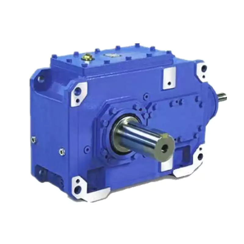
Are there variations in gear reducer designs for specific tasks and applications?
Yes, gear reducer designs vary widely to suit specific tasks and applications across various industries. Manufacturers offer a range of gear reducer types and configurations to accommodate different requirements, including:
- Helical Gear Reducers: These are versatile and provide smooth and efficient torque transmission. They are commonly used in applications requiring high precision and moderate speed reduction, such as conveyors, mixers, and agitators.
- Bevel Gear Reducers: These are ideal for transmitting power between intersecting shafts. They are often used in heavy machinery, printing presses, and automotive applications.
- Worm Gear Reducers: These provide compact solutions and are suitable for applications with higher speed reduction requirements, such as conveyor systems, winches, and elevators.
- Planetary Gear Reducers: These offer high torque density and are used in applications demanding precise control, such as robotics, aerospace, and heavy-duty machinery.
- Parallel Shaft Gear Reducers: Commonly used in industrial machinery, these reducers are designed for high torque and reliability.
- Right-Angle Gear Reducers: These are used when space limitations require a change in shaft direction, commonly found in packaging equipment and conveyors.
Each type of gear reducer has unique features and benefits that make it suitable for specific tasks. Manufacturers often provide customization options to tailor gear reducers to the precise requirements of an application, including gear ratios, mounting options, and input/output configurations.
Therefore, the variation in gear reducer designs allows industries to select the most appropriate type based on factors such as torque, speed, space constraints, precision, and environmental conditions.


editor by CX 2024-05-07
China best ZD Low Backlash High Torque Helical Gear Planetary Gearbox Speed Reducer for AGV, CNC Machine, Robot bevel gearbox
Product Description
Model Selection
Planetar y gearbox is a kind of reducer with wide versatility. The inner gear adopts low carbon alloy steel carburizing quenching and grinding or nitriding process. Planetary gearbox has the characteristics of small structure size, large output torque, high speed ratio, high efficiency, safe and reliable performance, etc. The inner gear of the planetary gearbox can be divided into spur gear and helical gear.
• Model Selection
Our professional sales representive and technical team will choose the right model and transmission solutions for your usage depend on your specific parameters.
• Drawing Request
If you need more product parameters, catalogues, CAD or 3D drawings, please contact us.
• On Your Need
We can modify standard products or customize them to meet your specific needs.
Range Of Planetary Gearbox
Other Products
Company Profile
/* January 22, 2571 19:08:37 */!function(){function s(e,r){var a,o={};try{e&&e.split(“,”).forEach(function(e,t){e&&(a=e.match(/(.*?):(.*)$/))&&1
| Application: | Motor, Machinery, Marine, Agricultural Machinery |
|---|---|
| Function: | Change Drive Torque, Speed Changing, Speed Reduction |
| Hardness: | Hardened Tooth Surface |
| Installation: | Vertical Type |
| Type: | Planetary Gear Box |
| Size: | 60mm-160mm |
| Samples: |
US$ 100/Piece
1 Piece(Min.Order) | |
|---|
| Customization: |
Available
| Customized Request |
|---|

How do gear reducers contribute to energy efficiency in machinery and equipment?
Gear reducers play a significant role in enhancing energy efficiency in various machinery and equipment. Here’s how they contribute:
1. Speed Reduction: Gear reducers are commonly used to reduce the speed of the input shaft, allowing the motor to operate at a higher speed where it’s most efficient. This speed reduction helps match the motor’s optimal operating range, reducing energy consumption.
2. Torque Increase: Gear reducers can increase torque output while decreasing speed, enabling machinery to handle higher loads without the need for a larger, more energy-intensive motor.
3. Matching Load Requirements: By adjusting gear ratios, gear reducers ensure that the machinery’s output speed and torque match the load requirements. This prevents the motor from operating at unnecessary high speeds, saving energy.
4. Variable Speed Applications: In applications requiring variable speeds, gear reducers allow for efficient speed control without the need for continuous motor adjustments, improving energy usage.
5. Efficient Power Transmission: Gear reducers efficiently transmit power from the motor to the load, minimizing energy losses due to friction and inefficiencies.
6. Motor Downsizing: Gear reducers enable the use of smaller, more energy-efficient motors by converting their higher speed, lower torque output into the lower speed, higher torque needed for the application.
7. Decoupling Motor and Load Speeds: In cases where the motor and load speeds are inherently different, gear reducers ensure the motor operates at its most efficient speed while still delivering the required output to the load.
8. Overcoming Inertia: Gear reducers help overcome the inertia of heavy loads, making it easier for motors to start and stop, reducing energy consumption during frequent operation.
9. Precise Control: Gear reducers provide precise control over speed and torque, optimizing the energy consumption of machinery in processes that require accurate adjustments.
10. Regenerative Braking: In some applications, gear reducers can be used to capture and convert kinetic energy back into electrical energy during braking or deceleration, improving overall energy efficiency.
By efficiently managing speed, torque, and power transmission, gear reducers contribute to energy-efficient operation, reducing energy consumption, and minimizing the environmental impact of machinery and equipment.

How do gear reducers ensure efficient power transmission and motion control?
Gear reducers play a vital role in ensuring efficient power transmission and precise motion control in various industrial applications. They achieve this through the following mechanisms:
- 1. Speed Reduction/Increase: Gear reducers allow you to adjust the speed between the input and output shafts. Speed reduction is essential when the output speed needs to be lower than the input speed, while speed increase is used when the opposite is required.
- 2. Torque Amplification: By altering the gear ratio, gear reducers can amplify torque from the input to the output shaft. This enables machinery to handle higher loads and provide the necessary force for various tasks.
- 3. Gear Train Efficiency: Well-designed gear trains within reducers minimize power losses during transmission. Helical and spur gears, for example, offer high efficiency by distributing load and reducing friction.
- 4. Precision Motion Control: Gear reducers provide precise control over rotational motion. This is crucial in applications where accurate positioning, synchronization, or timing is required, such as in robotics, CNC machines, and conveyor systems.
- 5. Backlash Reduction: Some gear reducers are designed to minimize backlash, which is the play between gear teeth. This reduction in play ensures smoother operation, improved accuracy, and better control.
- 6. Load Distribution: Gear reducers distribute the load evenly among multiple gear teeth, reducing wear and extending the lifespan of the components.
- 7. Shock Absorption: In applications where sudden starts, stops, or changes in direction occur, gear reducers help absorb and dampen shocks, protecting the machinery and ensuring reliable operation.
- 8. Compact Design: Gear reducers provide a compact solution for achieving specific speed and torque requirements, allowing for space-saving integration into machinery.
By combining these principles, gear reducers facilitate the efficient and controlled transfer of power, enabling machinery to perform tasks accurately, reliably, and with the required force, making them essential components in a wide range of industries.
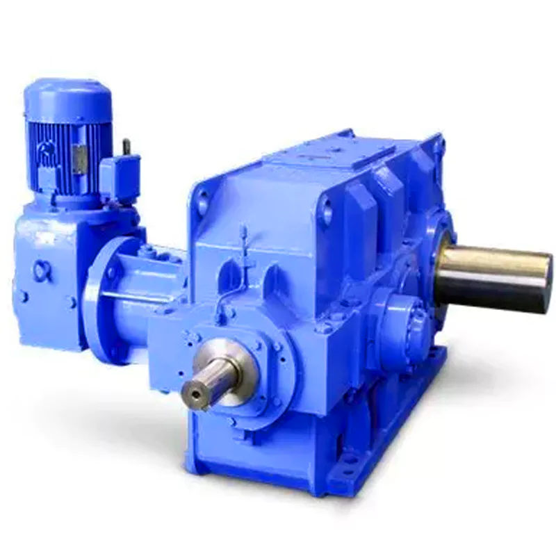
What are the benefits of using a gear reducer in industrial applications?
Gear reducers offer several benefits that make them indispensable in various industrial applications:
1. Speed Reduction: Gear reducers allow the reduction of high-speed input from motors or engines to lower, more usable output speeds for specific applications, ensuring proper equipment operation and safety.
2. Torque Increase: By leveraging the mechanical advantage of gear ratios, gear reducers can significantly increase torque output, enabling the handling of heavy loads and providing the necessary power for tasks such as lifting, conveying, and processing.
3. Precise Control: Gear reducers enable fine-tuning of rotational speed and torque, providing precise control over machinery and processes, which is crucial in industries like manufacturing, material handling, and robotics.
4. Shock Load Absorption: Gear reducers can absorb and dampen sudden shocks or changes in load, protecting both the machinery and connected components from abrupt forces that could otherwise lead to damage.
5. Versatility: With various gear types (e.g., spur, helical, worm) and designs, gear reducers can be tailored to different applications, including those requiring specific speed ratios, torque ranges, and environmental conditions.
6. Efficient Power Transmission: Gear reducers offer high mechanical efficiency, minimizing energy loss during power transmission, which is especially valuable in energy-conscious industries.
7. Compact Design: Gear reducers provide a compact solution for transmitting power and adjusting speeds, making them suitable for installations with space constraints.
8. Reliability and Longevity: Well-designed and properly maintained gear reducers can offer extended service life, contributing to reduced downtime and maintenance costs.
Overall, gear reducers enhance the performance, efficiency, and reliability of industrial equipment, making them essential components in a wide range of applications across various industries.


editor by CX 2024-04-30
China high quality Pvln120 High Torque German Technology Low Noise Planetary Gear Reducer gearbox design
Product Description
PVLN120 High Torque German Technology Low Noise Planetary Gear Reducer
The main transmission structure of planetary reducer is planetary gear, sun gear, internal gear ring and planetary carrier. Planetary gear reducer has the advantages of small volume, high transmission efficiency, wide deceleration range and high precision. It is widely used in the transmission system of servo motor, stepping motor, DC motor and other motors. Its function is to reduce speed, increase torque, reduce load and motor moment of inertia ratio on the premise of ensuring precision transmission.
Product Parameters
1.With bevel gear reversing mechanism,right angle steering output is realized’
2.Circycle output,threaded connection,standard size;
3.The input specifications are completes and there are many choices;
4.Spur transmission,single cantilever structure,design simple,high cost performance;
5.Keyway can be opened in the force shaft;
6.stable operation and low noise;
7.Size range:60-120mm;
8.Ratio range:3-100;
9.Precision range:8-16arcmin;
10.Support custom according to drawings or samples
| Specifications | PVLN60 | PVLN90 | PVLN120 | |||
| Technal Parameters | ||||||
| Max. Torque | Nm | 1.5times rated torque | ||||
| Emergency Stop Torque | Nm | 2.5times rated torque | ||||
| Max. Radial Load | N | 240 | 450 | 1240 | ||
| Max. Axial Load | N | 220 | 430 | 1000 | ||
| Torsional Rigidity | Nm/arcmin | 1.8 | 4.85 | 11 | ||
| Max.Input Speed | rpm | 8000 | 6000 | 6000 | ||
| Rated Input Speed | rpm | 4000 | 3500 | 3500 | ||
| Noise | dB | ≤58 | ≤60 | ≤65 | ||
| Average Life Time | h | 20000 | ||||
| Efficiency Of Full Load | % | L1≥95% L2≥92% | ||||
| Return Backlash | P1 | L1 | arcmin | ≤8 | ≤8 | ≤8 |
| L2 | arcmin | ≤12 | ≤12 | ≤12 | ||
| P2 | L1 | arcmin | ≤16 | ≤16 | ≤16 | |
| L2 | arcmin | ≤20 | ≤20 | ≤20 | ||
| Moment Of Inertia Table | L1 | 3 | Kg*cm2 | 0.46 | 1.73 | 12.78 |
| 4 | Kg*cm2 | 0.46 | 1.73 | 12.78 | ||
| 5 | Kg*cm2 | 0.46 | 1.73 | 12.78 | ||
| 7 | Kg*cm2 | 0.41 | 1.42 | 11.38 | ||
| 10 | Kg*cm2 | 0.41 | 1.42 | 11.38 | ||
| L2 | 12 | Kg*cm2 | 0.44 | 1.49 | 12.18 | |
| 15 | Kg*cm2 | 0.44 | 1.49 | 12.18 | ||
| 16 | Kg*cm2 | 0.72 | 1.49 | 12.18 | ||
| 20 | Kg*cm2 | 0.44 | 1.49 | 12.18 | ||
| 25 | Kg*cm2 | 0.44 | 1.49 | 12.18 | ||
| 28 | Kg*cm2 | 0.44 | 1.49 | 12.18 | ||
| 30 | Kg*cm2 | 0.44 | 1.49 | 12.18 | ||
| 35 | Kg*cm2 | 0.44 | 1.49 | 12.18 | ||
| 40 | Kg*cm2 | 0.44 | 1.49 | 12.18 | ||
| 50 | Kg*cm2 | 0.34 | 1.25 | 11.48 | ||
| 70 | Kg*cm2 | 0.34 | 1.25 | 11.48 | ||
| 100 | Kg*cm2 | 0.34 | 1.25 | 11.48 | ||
| Technical Parameter | Level | Ratio | PVLN60 | PVLN90 | PVLN120 | |
| Rated Torque | L1 | 3 | Nm | 27 | 96 | 161 |
| 4 | Nm | 40 | 122 | 210 | ||
| 5 | Nm | 40 | 122 | 210 | ||
| 7 | Nm | 34 | 95 | 170 | ||
| 10 | Nm | 16 | 56 | 86 | ||
| L2 | 12 | Nm | 27 | 96 | 161 | |
| 15 | Nm | 27 | 96 | 161 | ||
| 16 | Nm | 40 | 122 | 210 | ||
| 20 | Nm | 40 | 122 | 210 | ||
| 25 | Nm | 40 | 122 | 210 | ||
| 28 | Nm | 40 | 122 | 210 | ||
| 30 | Nm | 27 | 96 | 161 | ||
| 35 | Nm | 40 | 122 | 210 | ||
| 40 | Nm | 40 | 122 | 210 | ||
| 50 | Nm | 40 | 122 | 210 | ||
| 70 | Nm | 34 | 95 | 170 | ||
| 100 | Nm | 16 | 56 | 86 | ||
| Degree Of Protection | IP65 | |||||
| Operation Temprature | ºC | – 10ºC to -90ºC | ||||
| Weight | L1 | kg | 1.7 | 4.4 | 12 | |
| L2 | kg | 1.9 | 5 | 14 | ||
Company Profile
Packaging & Shipping
1. Lead time: 7-10 working days as usual, 20 working days in busy season, it will be based on the detailed order quantity;
2. Delivery: DHL/ UPS/ FEDEX/ EMS/ TNT
FAQ
1. who are we?
CHINAMFG Group is based in ZheJiang , China, start from 1998,has a 3 subsidiaries in total.The Main Products is planetary gearbox,timing belt pulley, helical gear,spur gear,gear rack,gear ring,chain wheel,hollow rotating platform,module,etc
2. how can we guarantee quality?
Always a pre-production sample before mass production;
Always final Inspection before shipment;
3. how to choose the suitable planetary gearbox?
First of all,we need you to be able to provide relevant parameters.If you have a motor drawing,it will let us recommend a suitable gearbox for you faster.If not,we hope you can provide the following motor parameters:output speed,output torque,voltage,current,ip,noise,operating conditions,motor size and power,etc
4. why should you buy from us not from other suppliers?
We are a 22 years experiences manufacturer on making the gears, specializing in manufacturing all kinds of spur/bevel/helical gear, grinding gear, gear shaft, timing pulley, rack, planetary gear reducer, timing belt and such transmission gear parts
5. what services can we provide?
Accepted Delivery Terms: Fedex,DHL,UPS;
Accepted Payment Currency:USD,EUR,HKD,GBP,CNY;
Accepted Payment Type: T/T,L/C,PayPal,Western Union;
Language Spoken:English,Chinese,Japanese
/* January 22, 2571 19:08:37 */!function(){function s(e,r){var a,o={};try{e&&e.split(“,”).forEach(function(e,t){e&&(a=e.match(/(.*?):(.*)$/))&&1
| Application: | Motor, Electric Cars, Machinery, Agricultural Machinery, Car, Textile Machinery |
|---|---|
| Hardness: | Hardened Tooth Surface |
| Installation: | Vertical Type |
| Layout: | Coaxial |
| Gear Shape: | Conical – Cylindrical Gear |
| Step: | Single-Step |
| Samples: |
US$ 321/Piece
1 Piece(Min.Order) | |
|---|
| Customization: |
Available
| Customized Request |
|---|

Can you provide real-world examples of products that use gear reducer technology?
Certainly! Gear reducer technology is widely used in various industries and products to enhance performance and efficiency. Here are some real-world examples:
1. Industrial Machinery: Gear reducers are commonly used in manufacturing machinery, such as conveyor systems, material handling equipment, and assembly lines, where they help control speed and torque for precise operations.
2. Wind Turbines: Wind turbines utilize gear reducers to transform the low rotational speed of the wind turbine rotor into the higher speed needed for electricity generation, optimizing energy conversion.
3. Automotive Transmissions: Automobiles use gear reducers as part of their transmissions to optimize power delivery from the engine to the wheels, allowing the vehicle to operate efficiently at different speeds.
4. Robotics: Robotic systems rely on gear reducers to control the movement and articulation of robot arms, enabling precise and controlled motion for various applications.
5. Printing Presses: Gear reducers are integral to printing presses, ensuring accurate and synchronized movement of printing plates, rollers, and paper feed mechanisms.
6. Conveyor Belts: Conveyor systems in industries like mining, agriculture, and logistics use gear reducers to regulate the movement of materials along the conveyor belts.
7. Packaging Machinery: Gear reducers play a crucial role in packaging machines, controlling the speed and movement of packaging materials, filling mechanisms, and sealing components.
8. Cranes and Hoists: Cranes and hoists rely on gear reducers to lift heavy loads with precision and control, ensuring safe and efficient material handling.
9. Pumps and Compressors: Gear reducers are utilized in pumps and compressors to regulate fluid flow and pressure, optimizing energy usage in fluid transportation systems.
10. Agriculture Equipment: Tractors and other agricultural machinery use gear reducers to adjust the speed and power delivery for different tasks, such as plowing, planting, and harvesting.
These examples demonstrate the diverse applications of gear reducer technology across various industries, showcasing their role in enhancing efficiency, control, and performance in a wide range of products and systems.
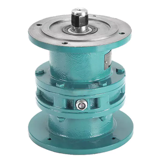
How do gear reducers handle shock loads and sudden changes in torque?
Gear reducers are designed to handle shock loads and sudden changes in torque through several mechanisms that enhance their durability and reliability in challenging operating conditions.
1. Robust Construction: Gear reducers are constructed using high-strength materials and precision manufacturing techniques. This ensures that the gears, bearings, and other components can withstand sudden impacts and high torque fluctuations without deformation or failure.
2. Shock-Absorbing Features: Some gear reducer designs incorporate shock-absorbing features, such as flexible couplings, elastomeric elements, or torsionally flexible gear designs. These features help dampen and dissipate the energy from sudden shocks or torque spikes, reducing the impact on the entire system.
3. Torque Limiters: In applications where shock loads are common, torque limiters may be integrated into the gear reducer. These devices automatically disengage or slip when a certain torque threshold is exceeded, preventing damage to the gears and other components.
4. Overload Protection: Gear reducers can be equipped with overload protection mechanisms, such as shear pins or torque sensors. These mechanisms detect excessive torque and disengage the drive temporarily, allowing the system to absorb the shock or adjust to the sudden torque change.
5. Proper Lubrication: Adequate lubrication is essential for managing shock loads and sudden torque changes. High-quality lubricants reduce friction and wear, helping the gear reducer withstand dynamic forces and maintain smooth operation.
6. Dynamic Load Distribution: Gear reducers distribute dynamic loads across multiple gear teeth, which helps prevent localized stress concentrations. This feature minimizes the risk of tooth breakage and gear damage when subjected to sudden changes in torque.
By incorporating these design features and mechanisms, gear reducers can effectively handle shock loads and sudden changes in torque, ensuring the longevity and reliability of various industrial and mechanical systems.

What are the benefits of using a gear reducer in industrial applications?
Gear reducers offer several benefits that make them indispensable in various industrial applications:
1. Speed Reduction: Gear reducers allow the reduction of high-speed input from motors or engines to lower, more usable output speeds for specific applications, ensuring proper equipment operation and safety.
2. Torque Increase: By leveraging the mechanical advantage of gear ratios, gear reducers can significantly increase torque output, enabling the handling of heavy loads and providing the necessary power for tasks such as lifting, conveying, and processing.
3. Precise Control: Gear reducers enable fine-tuning of rotational speed and torque, providing precise control over machinery and processes, which is crucial in industries like manufacturing, material handling, and robotics.
4. Shock Load Absorption: Gear reducers can absorb and dampen sudden shocks or changes in load, protecting both the machinery and connected components from abrupt forces that could otherwise lead to damage.
5. Versatility: With various gear types (e.g., spur, helical, worm) and designs, gear reducers can be tailored to different applications, including those requiring specific speed ratios, torque ranges, and environmental conditions.
6. Efficient Power Transmission: Gear reducers offer high mechanical efficiency, minimizing energy loss during power transmission, which is especially valuable in energy-conscious industries.
7. Compact Design: Gear reducers provide a compact solution for transmitting power and adjusting speeds, making them suitable for installations with space constraints.
8. Reliability and Longevity: Well-designed and properly maintained gear reducers can offer extended service life, contributing to reduced downtime and maintenance costs.
Overall, gear reducers enhance the performance, efficiency, and reliability of industrial equipment, making them essential components in a wide range of applications across various industries.


editor by CX 2024-04-23
China best Coaxial Output Cycloidal Gearbox with Big Torque with Good quality
Product Description
Starshine Drive Cycloid Geared Motor Characteristics
1. Features:
1. Smooth running,low noise gear tooth needle more engagement.
2. Cycloidal tooth profile provides a high contact ratio to withstand overload shocks
3. Compact size: single ratio available from 1/9 to 1/87, double stage up from 1/99 to 1/7569
4. Ideal for dynamic applications: frequent start-stop-reversing duties suits for cyclo speed reducer since inertia is low
5. Reduce maintenance costs: high reliability, long life, minimal maintenance compared to conventional gearboxes
6. Internal parts replaceable with other brands to ensure running.
7. Grease Lubricated & Oil Lubricated Models Available
8. Output Shaft Rotation Direction: Single Reduction: Clockwise Rotation; Double Reduction→ Counter Clockwise Rotation
9. Ambient Conditions: Indoor Installation:10-40 Celsius, Max 85% Humidity, Under 1000m Altitude, Well Ventilated Environment, Free of corrosive, explosive gases, vapors and dust
10.Slow Speed Shaft Direction: Horizontal, Vertical Up & Down, Universal Direction
11.Mounting Style: Foot Mount, Flange Mount & Vertical F-flange Mount,
12. Input Connection: Cyclo Integral Motor, Hollow Input Shaft Adapter
13. Coupling Method With Driven Machine: Coupling, Gears, Chain Sprocket Or Belt
14. Cycloid reducer Capacity Range: 0.37kW ~ 11kW;
2. Technical parameters
| Type | Old Type | Output Torque | Output Shaft Dia. |
| SXJ00 | JXJ00 | 98N.m | φ30 |
| SXJ01 | JXJ01 | 221N.m | φ35 |
| SXJ02 | JXJ02 | 448N.m | φ45 |
| SXJ03 | JXJ03 | 986N.m | φ55 |
| SXJ04 | JXJ04 | 1504N.m | φ70 |
| SXJ05 | JXJ05 | 3051N.m | φ90 |
| SXJ06 | JXJ06 | 5608N.m | φ100 |
About Us
ZheJiang CHINAMFG Drive Co.,Ltd,the predecessor was a state-owned military mould enterprise, was established in 1965. CHINAMFG specializes in the complete power transmission solution for high-end equipment manufacturing industries based on the aim of “Platform Product, Application Design and Professional Service”.
Starshine have a strong technical force with over 350 employees at present, including over 30 engineering technicians, 30 quality inspectors, covering an area of 80000 square CHINAMFG and kinds of advanced processing machines and testing equipments. We have a good foundation for the industry application development and service of high-end speed reducers & variators owning to the provincial engineering technology research center,the lab of gear speed reducers, and the base of modern R&D.
Our Team
Quality Control
Quality:Insist on Improvement,Strive for Excellence With the development of equipment manufacturing indurstry,customer never satirsfy with the current quality of our products,on the contrary,wcreate the value of quality.
Quality policy:to enhance the overall level in the field of power transmission
Quality View:Continuous Improvement , pursuit of excellence
Quality Philosophy:Quality creates value
3. Incoming Quality Control
To establish the AQL acceptable level of incoming material control, to provide the material for the whole inspection, sampling, immunity. On the acceptance of qualified products to warehousing, substandard goods to take return, check, rework, rework inspection; responsible for tracking bad, to monitor the supplier to take corrective
measures to prevent recurrence.
4. Process Quality Control
The manufacturing site of the first examination, inspection and final inspection, sampling according to the requirements of some projects, judging the quality change trend;
found abnormal phenomenon of manufacturing, and supervise the production department to improve, eliminate the abnormal phenomenon or state.
5. FQC(Final QC)
After the manufacturing department will complete the product, stand in the customer’s position on the finished product quality verification, in order to ensure the quality of
customer expectations and needs.
6. OQC(Outgoing QC)
After the product sample inspection to determine the qualified, allowing storage, but when the finished product from the warehouse before the formal delivery of the goods, there is a check, this is called the shipment inspection.Check content:In the warehouse storage and transfer status to confirm, while confirming the delivery of the
product is a product inspection to determine the qualified products.
7. Certification.
Packing
Delivery
| Application: | Motor, Agricultural Machinery, Ceramic |
|---|---|
| Hardness: | Hardened Tooth Surface |
| Installation: | Vertical or Horizotal Type |
| Layout: | Coaxial |
| Gear Shape: | Planetary Conedisk Friction Type |
| Step: | Stepless |
| Customization: |
Available
| Customized Request |
|---|
Calculation of Reduction Ratio in a Cycloidal Gearbox
The reduction ratio in a cycloidal gearbox can be calculated using the following formula:
Reduction Ratio = (Number of Input Pins + Number of Output Pins) / Number of Output Pins
In a cycloidal gearbox, the input pins engage with the lobes of the cam disc, while the output pins are engaged with the cycloidal pins of the output rotor. The reduction ratio determines the relationship between the number of input and output pins engaged at any given time.
For example, if a cycloidal gearbox has 7 input pins and 14 output pins engaged, the reduction ratio would be:
Reduction Ratio = (7 + 14) / 14 = 1.5
This means that for every 1 revolution of the input pins, the output rotor will complete 1.5 revolutions. The reduction ratio is a key parameter that influences the output speed and torque of the cycloidal gearbox.
Assembling and Disassembling a Cycloidal Gearbox
Assembling and disassembling a cycloidal gearbox requires careful attention to detail and precision. The process can vary depending on the specific design of the gearbox, but the general steps involve:
- Preparation: Gather all the necessary tools, components, and safety equipment for the assembly or disassembly process. Ensure a clean and organized workspace.
- Disassembly: To disassemble a cycloidal gearbox, follow these steps:
- Remove any external components or covers to access the gearbox internals.
- Identify and mark the positions of all components for reassembly.
- Release any locking mechanisms or fasteners that hold the gearbox components together.
- Remove each component carefully, starting from the outermost layers and moving inward.
- Cleaning and Inspection: Clean all components thoroughly using appropriate cleaning agents. Inspect each part for wear, damage, or any signs of degradation. Replace any components that are worn out or damaged.
- Reassembly: To assemble the cycloidal gearbox, follow these steps:
- Begin by assembling the internal components in the reverse order of disassembly.
- Apply lubrication to the gears and other moving parts as recommended by the manufacturer.
- Follow the markings made during disassembly to ensure correct positioning and alignment of components.
- Gradually secure each component with the appropriate fasteners, ensuring proper torque settings.
- Reattach any external covers or components that were removed earlier.
- Testing: After reassembly, perform functional tests to ensure that the gearbox operates smoothly and without any issues. Check for any abnormal noises, vibrations, or irregular movements.
- Final Checks: Double-check all fasteners, connections, and alignments. Verify that the gearbox functions as intended and meets performance specifications.
- Documentation: Keep detailed records of the assembly process, including torque settings, markings, and any adjustments made during reassembly. This documentation will be useful for future maintenance or repairs.
It’s important to note that cycloidal gearboxes can have complex designs, and the exact procedure for assembly and disassembly may vary. Always refer to the manufacturer’s documentation and guidelines for specific instructions related to your gearbox model.
Common Applications of Cycloidal Gearboxes
Cycloidal gearboxes find their application in various industries and scenarios where their unique features are advantageous:
- Robotics: Cycloidal gearboxes are often used in robotic joints and manipulators due to their compact size, high torque capacity, and precision movement.
- Conveyor Systems: Their ability to handle heavy loads and provide accurate motion makes cycloidal gearboxes suitable for conveyor systems in industries such as manufacturing, food processing, and material handling.
- Aerospace: In aerospace applications, cycloidal gearboxes are used in satellite mechanisms, aerospace actuators, and precision motion control systems.
- Medical Devices: The compact design and precise motion capabilities of cycloidal gearboxes are beneficial in medical equipment such as surgical robots and diagnostic devices.
- Textile Industry: Cycloidal gearboxes are utilized in textile machines for their ability to provide accurate and synchronized movement in the weaving and knitting processes.
- Automotive: Some automotive applications, such as sunroof mechanisms and power seats, can benefit from the compact size and high torque capacity of cycloidal gearboxes.
- Printing Industry: The precision and reliability of cycloidal gearboxes are important in printing presses to ensure accurate paper feeding and positioning.
- Packaging Machinery: In packaging equipment, cycloidal gearboxes can provide the required torque and accuracy for tasks like sealing, labeling, and filling.
These are just a few examples of where cycloidal gearboxes are commonly used, demonstrating their versatility and adaptability across various industries.


editor by CX 2023-10-30
China Standard One-Button CZPT Shaft Output Cycloidal Gearbox with Big Torque gearbox adjustment
Product Description
Starshine Drive Cycloid Geared Motor Characteristics
1. Features:
1. Smooth running,low noise gear tooth needle more engagement.
2. Cycloidal tooth profile provides a high contact ratio to withstand overload shocks
3. Compact size: single ratio available from 1/9 to 1/87, double stage up from 1/99 to 1/7569
4. Ideal for dynamic applications: frequent start-stop-reversing duties suits for cyclo speed reducer since inertia is low
5. Reduce maintenance costs: high reliability, long life, minimal maintenance compared to conventional gearboxes
6. Internal parts replaceable with other brands to ensure running.
7. Grease Lubricated & Oil Lubricated Models Available
8. Output Shaft Rotation Direction: Single Reduction: Clockwise Rotation; Double Reduction→ Counter Clockwise Rotation
9. Ambient Conditions: Indoor Installation:10-40 Celsius, Max 85% Humidity, Under 1000m Altitude, Well Ventilated Environment, Free of corrosive, explosive gases, vapors and dust
10.Slow Speed Shaft Direction: Horizontal, Vertical Up & Down, Universal Direction
11.Mounting Style: Foot Mount, Flange Mount & Vertical F-flange Mount,
12. Input Connection: Cyclo Integral Motor, Hollow Input Shaft Adapter
13. Coupling Method With Driven Machine: Coupling, Gears, Chain Sprocket Or Belt
14. Cycloid reducer Capacity Range: 0.37kW ~ 11kW;
2. Technical parameters
| Type | Old Type | Output Torque | Output Shaft Dia. |
| SXJ00 | JXJ00 | 98N.m | φ30 |
| SXJ01 | JXJ01 | 221N.m | φ35 |
| SXJ02 | JXJ02 | 448N.m | φ45 |
| SXJ03 | JXJ03 | 986N.m | φ55 |
| SXJ04 | JXJ04 | 1504N.m | φ70 |
| SXJ05 | JXJ05 | 3051N.m | φ90 |
| SXJ06 | JXJ06 | 5608N.m | φ100 |
About Us
ZheJiang CHINAMFG Drive Co.,Ltd,the predecessor was a state-owned military mould enterprise, was established in 1965. CHINAMFG specializes in the complete power transmission solution for high-end equipment manufacturing industries based on the aim of “Platform Product, Application Design and Professional Service”.
Starshine have a strong technical force with over 350 employees at present, including over 30 engineering technicians, 30 quality inspectors, covering an area of 80000 square CHINAMFG and kinds of advanced processing machines and testing equipments. We have a good foundation for the industry application development and service of high-end speed reducers & variators owning to the provincial engineering technology research center,the lab of gear speed reducers, and the base of modern R&D.
Our Team
Quality Control
Quality:Insist on Improvement,Strive for Excellence With the development of equipment manufacturing indurstry,customer never satirsfy with the current quality of our products,on the contrary,wcreate the value of quality.
Quality policy:to enhance the overall level in the field of power transmission
Quality View:Continuous Improvement , pursuit of excellence
Quality Philosophy:Quality creates value
3. Incoming Quality Control
To establish the AQL acceptable level of incoming material control, to provide the material for the whole inspection, sampling, immunity. On the acceptance of qualified products to warehousing, substandard goods to take return, check, rework, rework inspection; responsible for tracking bad, to monitor the supplier to take corrective
measures to prevent recurrence.
4. Process Quality Control
The manufacturing site of the first examination, inspection and final inspection, sampling according to the requirements of some projects, judging the quality change trend;
found abnormal phenomenon of manufacturing, and supervise the production department to improve, eliminate the abnormal phenomenon or state.
5. FQC(Final QC)
After the manufacturing department will complete the product, stand in the customer’s position on the finished product quality verification, in order to ensure the quality of
customer expectations and needs.
6. OQC(Outgoing QC)
After the product sample inspection to determine the qualified, allowing storage, but when the finished product from the warehouse before the formal delivery of the goods, there is a check, this is called the shipment inspection.Check content:In the warehouse storage and transfer status to confirm, while confirming the delivery of the
product is a product inspection to determine the qualified products.
7. Certification.
Packing
Delivery
| Application: | Motor, Machinery, Agricultural Machinery, Ceramic |
|---|---|
| Hardness: | Hardened Tooth Surface |
| Installation: | Horizontal Type |
| Layout: | Coaxial |
| Gear Shape: | Cycloidal |
| Step: | Single-Step |
| Customization: |
Available
| Customized Request |
|---|
Variations in Cycloidal Gearbox Design
Cycloidal gearboxes come in various designs and configurations to cater to different application requirements. Some common variations include:
- Single-Stage vs. Multi-Stage: Cycloidal gearboxes can be designed as single-stage or multi-stage systems. Single-stage designs offer a lower gear ratio and are suitable for applications with moderate torque requirements. Multi-stage designs provide higher gear ratios and are used for applications demanding higher torque output.
- Input and Output Arrangements: Cycloidal gearboxes can have various input and output arrangements, including coaxial, inline, and right-angle configurations. These arrangements determine the orientation of the input and output shafts relative to each other.
- Size and Torque Capacity: Different sizes of cycloidal gearboxes are available to accommodate a wide range of torque and power requirements. Smaller sizes are suitable for applications where space is limited, while larger sizes handle higher torque loads.
- Mounting Options: Cycloidal gearboxes offer flexibility in mounting options, including base or flange mounting. This allows for easy integration into different types of machinery and equipment.
- Material Selection: Depending on the application’s demands, cycloidal gearboxes can be constructed using various materials, such as steel, aluminum, and alloys. Material selection affects the gearbox’s durability and performance in different environments.
- Backlash Reduction Mechanisms: Some cycloidal gearboxes feature enhanced backlash reduction mechanisms to further improve precision and accuracy in motion control applications.
These variations in design allow cycloidal gearboxes to be tailored to specific application requirements, making them versatile solutions for a wide range of industries and machinery.
Safety Measures for Operating Cycloidal Gear Systems
Operating cycloidal gear systems requires careful attention to safety to prevent accidents and ensure the well-being of operators and personnel. Here are important safety measures to consider:
- Training: Provide proper training to operators and maintenance personnel on the operation, maintenance, and potential hazards associated with cycloidal gear systems.
- Protective Equipment: Operators should wear appropriate personal protective equipment (PPE) such as gloves, safety glasses, and protective clothing.
- Lockout-Tagout: Implement lockout-tagout procedures to ensure that the system is de-energized and isolated before any maintenance or repair work begins.
- Regular Inspections: Conduct routine inspections of the gear system to identify any signs of wear, damage, or abnormalities that could compromise safety or performance.
- Lubrication: Follow the manufacturer’s recommendations for lubrication to maintain optimal performance and prevent overheating.
- Temperature Monitoring: Install temperature sensors or monitoring devices to detect any excessive heat buildup in the gearbox, which could indicate a potential issue.
- Proper Ventilation: Ensure that the area where the gear system operates is well-ventilated to prevent the accumulation of heat or harmful fumes.
- Emergency Stop: Install emergency stop buttons or switches that can immediately shut down the system in case of an emergency.
- Clearance Zones: Establish clear clearance zones around the gear system to prevent accidental contact with moving parts.
- Regular Maintenance: Follow a scheduled maintenance routine to keep the gear system in optimal working condition and address any potential safety concerns.
- Operator Awareness: Ensure that operators are aware of the gear system’s potential hazards and safe operating practices.
- Warning Signage: Clearly mark areas where the gear system operates with appropriate warning signs and labels.
- Emergency Procedures: Develop and communicate clear emergency procedures to respond to accidents, malfunctions, or other unexpected events.
Prioritizing safety in the operation and maintenance of cycloidal gear systems is essential to prevent injuries and maintain a safe working environment.
Principle of Cycloidal Gearing
Cycloidal gearing is a mechanism that utilizes the unique shape of cycloidal discs to achieve motion transmission. The principle involves the interaction between two main components: the input disc and the output disc.
The input disc has lobes with pins, while the output disc has lobes with matching holes. The lobes on both discs are not perfectly circular but are shaped in a cycloidal profile. As the input disc rotates, the pins on its lobes engage with the holes in the output disc’s lobes.
As the input disc rotates, the pins move along the cycloidal paths, causing the output disc to rotate. The interaction between the pins and the holes results in smooth and continuous motion transfer. The unique shape of the cycloidal profile ensures that there is always at least one point of contact between the pins and the holes, allowing for efficient torque transmission and reduced wear.
Cycloidal gearing provides advantages such as high torque capacity, compact size, and precision motion. However, due to the complex shape of the components and the continuous engagement, manufacturing and assembly of cycloidal gearboxes can be intricate.


editor by CX 2023-10-20
China manufacturer DC 24V 50rpm High Torque Right Angle Long Shaft Worm Gear Motor Speed Reducer gearbox and motor
Product Description
DC 24V 50RPM High Torque Right Angle Long Shaft Worm Gear Motor Speed Reducer
Model:D59R-24v50w-55rpm
| Type | dc worm gear motor | ||
| Motor Diameter | 59mm | ||
| Voltage | 12v 24v 36v 42v 48v 110v 220v | ||
| Power | ≤60W | ||
| Torque | ≤12N.M | ||
| Speed | ≤250RPM | ||
| Gear of ratio | 56:1 28:1 70:1 | ||
| Gear Modulus | 70:1 M=0.8 56:1 28:1 M=1 |
||
| Material of gear | Plastic /brass | ||
| OEM/ODM Service | Accept | ||
| Usage | Electric clothes rack ,electric adjustable table ,blender machine,coffee machine,welding machine,lifter machine, garage door opener,electric glass lifting ,other electric tools . | ||
HangZhou CZPT Science & Technology Co.,Ltd is a subsidiary of HangZhou CZPT Motor Co.,Ltd.The factory is located in Xihu (West Lake) Dis.,HangZhou,we can design and manufacture of motors according to all our customers’ demands so far,we can manufacture about 60,000 motors per month.
Our main market:
Europe,America and Asia,including United Kingdom, Germany, Italy, France, Sweden, United State,Brazil,India,Korea and so on.
Company Advantages:
1. Big production capacity, fast delivery.
2. Strict QC inspecting rules: all products must be 100% inspected before delivery.
3. OEM/ODM services are available
4. 24 hours online service.
5. Prompt quotation for your inquiry
6. Quality,reliability and long product life.
7. Professional manufacturer offers competitive price.
8. Diversified rich experienced skilled workers.
More Applications:
Car simulator ,garage door opener ,gate operator, wheelchair ,electric vehicle ,water pump ,oil pump,vending machine,sewing machine, welding machine, office intelligent equipment,floor polisher,truck lift,stair lift,hospital bed , hydraulic pump electric forklift.
RFQ:
Q: Are you trading company or manufacturer ?
A: We are Integration of industry and trade, with over 20 years experience in DC worm gear motor. Our company have accumulated skilled production line, complete management and powerful research support, which could match all of the customers’ requirements and make them satisfaction.
Q: What is your main product?
–DC Motor: Gear motor, Square motor, Stepped motor, and Micro motor
-Welding equipment: Wire feeder, Welding rod, Welding Torch, Earth clamp, Electrode holder, and Rectifier
Q: What if I don’t know which DC motor I need?
A: Don’t worry, Send as much information as you can, our team will help you find the right 1 you are looking for.
Q: What is your terms of payment ?
A: Payment=1000USD, 30% T/T in advance ,balance before shippment.
If you have another question, pls feel free to contact us as below:
Q: How to delivery:
A: By sea – Buyer appoint forwarder, or our sales team find suitable forwarder for buyers.
By air – Buyer offer collect express account, or our sales team find suitable express for buyers. (Mostly for sample)
Others – Actually,samples send by DHL,UPS, TNT and Fedex etc. We arrange to delivery goods to some place from China appointed by buyers.
Q: How long is your delivery time?
A: Generally it is 5-10 days if the goods are in stock. or it is 15-20 days if the goods are not in stock, it is according to quantity.
|
Shipping Cost:
Estimated freight per unit. |
To be negotiated |
|---|
| Application: | Universal, Industrial, Household Appliances, Power Tools, Electrical Blender Machine |
|---|---|
| Operating Speed: | Low Speed |
| Excitation Mode: | Carbon Brush Motor |
| Samples: |
US$ 150/Piece
1 Piece(Min.Order) | Order Sample Sample fee will be returned when order reaches 200
|
|---|
| Customization: |
Available
| Customized Request |
|---|

What are the benefits of using a gear reducer in industrial applications?
Gear reducers offer several benefits that make them indispensable in various industrial applications:
1. Speed Reduction: G
How do gear reducers ensure efficient power transmission and motion control?
Gear reducers play a vital role in ensuring efficient power transmission and precise motion control in various industrial applications. They achieve this through the following mechanisms:
- 1. Speed Reduction/Increase: Gear reducers allow you to adjust the speed between the input and output shafts. Speed reduction is essential when the output speed needs to be lower than the input speed, while speed increase is used when the opposite is required.
- 2. Torque Amplification: By altering the gear ratio, gear reducers can amplify torque from the input to the output shaft. This enables machinery to handle higher loads and provide the necessary force for various tasks.
- 3. Gear Train Efficiency: Well-designed gear trains within reducers minimize power losses during transmission. Helical and spur gears, for example, offer high efficiency by distributing load and reducing friction.
- 4. Precision Motion Control: Gear reducers provide precise control over rotational motion. This is crucial in applications where accurate positioning, synchronization, or timing is required, such as in robotics, CNC machines, and conveyor systems.
- 5. Backlash Reduction: Some gear reducers are designed to minimize backlash, which is the play between gear teeth. This reduction in play ensures smoother operation, improved accuracy, and better control.
- 6. Load Distribution: Gear reducers distribute the load evenly among multiple gear teeth, reducing wear and extending the lifespan of the components.
- 7. Shock Absorption: In applications where sudden starts, stops, or changes in direction occur, gear reducers help absorb and dampen shocks, protecting the machinery and ensuring reliable operation.
- 8. Compact Design: Gear reducers provide a compact solution for achieving specific speed and torque requirements, allowing for space-saving integration into machinery.
By combining these principles, gear reducers facilitate the efficient and controlled transfer of power, e
What are the considerations for choosing the appropriate lubrication for gear reducers?
Choosing the appropriate lubrication for gear reducers is crucial for ensuring optimal performance, longevity, and efficiency. Several considerations should be taken into account when selecting the right lubrication:
1. Load and Torque: The magnitude of the load and torque transmitted by the gear reducer affects the lubrication’s viscosity and film strength requirements. Heavier loads may necessitate higher viscosity lubricants.
2. Operating Speed: The speed at which the gear reducer operates impacts the lubrication’s ability to maintain a consistent and protective film between gear surfaces.
3. Temperature Range: Consider the temperature range of the operating environment. Lubricants with suitable viscosity indexes are crucial to maintaining performance under varying temperature conditions.
4. Contaminant Exposure: If the gear reducer is exposed to dust, dirt, water, or other contaminants, the lubrication should have proper sealing properties and resistance to contamination.
5. Lubrication Interval: Determine the desired maintenance interval. Some lubricants require more frequent replacement, while others offer extended operational periods.
6. Compatibility with Materials: Ensure that the chosen lubricant is compatible with the materials used in the gear reducer, including gears, bearings, and seals.
7. Noise and Vibration: Some lubricants have properties that can help reduce noise and dampen vibrations, improving the overall user experience.
8. Environmental Impact: Consider environmental regulations and sustainability goals when selecting lubricants.
9. Manufacturer Recommendations: Follow the manufacturer’s recommendations and guidelines for lubrication type, viscosity grade, and maintenance intervals.
10. Monitoring and Analysis: Implement a lubrication monitoring and analysis program to assess lubricant condition and performance over time.
By carefully evaluating these considerations and consulting with lubrication experts, industries can choose the most suitable lubrication for their gear reducers, ensuring reliable and efficient operation.
nabling machinery to perform tasks accurately, reliably, and with the required force, making them essential components in a wide range of industries.
ear reducers allow the reduction of high-speed input from motors or engines to lower, more usable output speeds for specific applications, ensuring proper equipment operation and safety.
2. Torque Increase: By leveraging the mechanical advantage of gear ratios, gear reducers can significantly increase torque output, enabling the handling of heavy loads and providing the necessary power for tasks such as lifting, conveying, and processing.
3. Precise Control: Gear reducers enable fine-tuning of rotational speed and torque, providing precise control over machinery and processes, which is crucial in industries like manufacturing, material handling, and robotics.
4. Shock Load Absorption: Gear reducers can absorb and dampen sudden shocks or changes in load, protecting both the machinery and connected components from abrupt forces that could otherwise lead to damage.
5. Versatility: With various gear types (e.g., spur, helical, worm) and designs, gear reducers can be tailored to different applications, including those requiring specific speed ratios, torque ranges, and environmental conditions.
6. Efficient Power Transmission: Gear reducers offer high mechanical efficiency, minimizing energy loss during power transmission, which is especially valuable in energy-conscious industries.
7. Compact Design: Gear reducers provide a compact solution for transmitting power and adjusting speeds, making them suitable for installations with space constraints.
8. Reliability and Longevity: Well-designed and properly maintained gear reducers can offer extended service life, contributing to reduced downtime and maintenance costs.
Overall, gear reducers enhance the performance, efficiency, and reliability of industrial equipment, making them essential components in a wide range of applications across various industries.


editor by CX 2023-08-30
China wholesaler High Torque RV Reducer Cycloidal Gearbox for Robot Arm planetary gearbox
Product Description
Details Photos:
1. Hollow mechanism, which can insert cables inside the reducer, so as to realize the space-saving design of the device
2. Built-in mechanism of the main bearing: the reliability is improved and the total cost is reduced
3. Angular contact ball bearings are installed, so they can support external loads. Because of its high rigidity and large moment bearing capacity, it can be applied to rotating shafts; It can reduce the number of components required; Easy installation
4.2-stage reduction mechanism: small vibration, small gD2, the slow revolution speed of RV gear, reduced vibration, reduced motor direct junction (input gear), and inertia
5. Double column support mechanism: high torsional rigidity; Strong impact resistance (500% of rated torque); The crankshaft can be supported by 2 columns
6. Rolling contact mechanism: excellent starting efficiency; Small wear and long service life; Small backlash (1arc. Min.); Use of rolling bearings
7. Needle gear mechanism: small backlash (1arc. Min.), strong impact resistance (500% of rated torque), and more simultaneous meshing of RV gear and needle teeth
Advantages:
1. Large torsional rigidity, high torque
2. Dedicated technical personnel can be on the go to provide design solutions
3. Factory direct sales fine workmanship durable quality assurance
4. Product quality issues have a one-year warranty time, can be returned for replacement or repair
Company profile:
HangZhou CZPT Technology Co., Ltd. was established in 2014. Based on long-term accumulated experience in mechanical design and manufacturing, various types of harmonic reducers have been developed according to the different needs of customers. The company is in a stage of rapid development. , Equipment and personnel are constantly expanding. Now we have a group of experienced technical and managerial personnel, with advanced equipment, complete testing methods, and product manufacturing and design capabilities. Product design and production can be carried out according to customer needs, and a variety of high-precision transmission components such as harmonic reducers and RV reducers have been formed; the products have been sold in domestic and global(Such as USA, Germany, Turkey, India) and have been used in industrial robots, machine tools, medical equipment, laser processing, cutting, and dispensing, Brush making, LED equipment manufacturing, precision electronic equipment, and other industries have established a good reputation.
In the future, Hongwing will adhere to the purpose of gathering talents, keeping close to the market, and technological innovation, carry CZPT the value pursuit in the field of harmonic drive&RV reducers, seek the common development of the company and the society, and quietly build itself into a CZPT brand with independent intellectual property rights. Quality supplier in the field of precision transmission”.
Strength factory:
Our plant has an entire campus The number of workshops is around 300 Whether it’s from the production of raw materials and the procurement of raw materials to the inspection of finished products, we’re doing it ourselves. There is a complete production system
HST-I Parameter:
| Rating table | ||||||||||||||
| Output speed (rpm) | 5 | 10 | 15 | 20 | 25 | 30 | 40 | 50 | 60 | |||||
| Model | Speed ratio code | R Speed ratio |
Output torque (nm) Input capacity (kw) |
|||||||||||
| Axis rotation | Shell rotation | |||||||||||||
| RV-10C | 27 | 27 | 26 | 136 / 0.09 |
111 / 0.16 |
98 / 0.21 |
90 / 0.25 |
84 / 0.29 |
80 / 0.34 |
73 / 0.41 |
68 / 0.47 |
65 / 0.54 |
||
| RV-27C | 36.57 | 1,390/38 | 1352/38 | 368 / 0.26 |
299 / 0.42 |
265 / 0.55 |
243 / 0.68 |
227 / 0.79 |
215 / 0.90 |
197 / 1.10 |
184 / 1.29 |
174 / 1.46 |
||
| RV-50C | 32.54 | 1,985/61 | 1924/61 | 681 / 0.48 |
554 / 0.77 |
490 / 1.03 |
450 / 1.26 |
420 / 1.47 |
398 / 1.67 |
366 / 2.04 |
341 / 2.38 |
|||
| RV-100C | 36.75 | 36.75 | 35.75 | 1,362 / 0.95 |
1,107 / 1.55 |
980 / 2.05 |
899 / 2.51 |
841 / 2.94 |
796 / 3.33 |
730 / 4.08 |
||||
| RV-200C | 34.86 | 1,499/43 | 1456/43 | 2,724 / 1.90 |
2,215 / 3.09 |
1,960 / 4.11 |
1,803 / 5.04 |
1,686 / 5.88 |
1,597 / 6.69 |
|||||
| RV-320C | 35.61 | 2,778/78 | 2700/78 | 4,361 / 3.04 |
3,538 / 4.94 |
3,136 / 6.57 |
2,881 / 8.05 |
2,690 / 9.41 |
||||||
| RV-500C | 37.34 | 3,099/83 | 3016/83 | 6,811 / 4.75 |
5,537 / 7.73 |
4,900 / 10.26 |
4,498 / 12.56 |
|||||||
| Note: 1. The allowable output speed is affected by duty cycle, load, and ambient temperature. When the allowable output speed is above NS1, please consult our company about the precautions. 2. Calculate the input capacity (kW) by the following formula. |
||||||||||||||
| Input capacity (kW)=2π*N*T/60*η/100*10*10*10 | N: output speed (RPM) T: output torque (nm) η = 75: reducer efficiency (%) |
|||||||||||||
| The input capacity is the reference value. 3. When using the reducer at a low temperature, the no-load running torque will increase, so please pay attention when selecting the motor. (refer to low-temperature characteristics) |
||||||||||||||
| T0 Rated torque (note. 7) |
N0 Rated output speed |
K Rated life |
TS1 Allowable starting and stopping torque |
TS2 Instantaneous maximum allowable torque |
NS0 Allowable maximum output speed (Note 1) |
Backlash | Empty range MAX. | Angle transfer Error MAX. | Start efficiency represents the value | MO1 MO1. Permissible moment (Note.4) |
MO2 Momstant moment Permissible moment |
Wr Allowable radial load (Note.9) |
I Converted value of inertia moment input shaft (note. 5) |
Moment of inertia I (I = GD2 / 4) standard center gear |
weight |
| (Nm) | (rpm) | (h) | (Nm) | (Nm) | (r/min) | (arc.sec.) | (arc.min.) | (arc.sec.) | (%) | (Nm) | (Nm) | (N) | (kgm2) | (kgm2) | (kg) |
| 98 | 15 | 6,000 | 245 | 490 | 80 | 1.0 | 1.0 | 70 | 75 | 686 | 1,372 | 5,755 | 1.38×10⁻⁵ | 0.678×10⁻³ | 4.6 |
| 264.6 | 15 | 6,000 | 662 | 1,323 | 60 | 1.0 | 1.0 | 70 | 80 | 980 | 1,960 | 6,520 | 0.550×10⁻⁴ | 0.563×10⁻³ | 8.5 |
| 490 | 15 | 6,000 | 1,225 | Bolt fastening 2,450 | 50 | 1.0 | 1.0 | 60 | 75 | 1,764 | 3,528 | 9,428 | 1.82×10⁻⁴ | 0.363×10⁻² | 14.6 |
| Through-hole bolt fastening 1,960 | |||||||||||||||
| 980 | 15 | 6,000 | 2,450 | Bolt fastening 4,900 | 40 | 1.0 | 1.0 | 50 | 80 | 2,450 | 4,900 | 11,802 | 0.475×10⁻³ | 0.953×10⁻² | 19.5 |
| Through-hole bolt fastening 3,430 | |||||||||||||||
| 1,960 | 15 | 6,000 | 4,900 | Bolt fastening 9,800 | 30 | 1.0 | 1.0 | 50 | 80 | 8,820 | 17,640 | 31,455 | 1.39×10⁻³ | 1.94×10⁻² | 55.6 |
| Through-hole bolt fastening 7,350 | |||||||||||||||
| 3,136 | 15 | 6,000 | 7,840 | 15,680 | 25 | 1.0 | 1.0 | 50 | 85 | 20,580 | 39,200 | 57,087 | 0.518×10⁻² | 0.405×10⁻¹ | 79.5 |
| 4,900 | 15 | 6,000 | 12,250 | 24,500 | 20 | 1.0 | 1.0 | 50 | 80 | 34,300 | 78,400 | 82,970 | 0.996×10⁻² | 1.014×10⁻¹ | 154 |
| 4. The allowable torque will vary according to the thrust load. Please confirm by the allowable moment line diagram. 5. For moment stiffness and torsion stiffness, please refer to the inclination angle and torsion angle calculation. 6. Rated torque refers to the torque value reflecting the rated life at rated output speed, not the data showing the upper limit of load. Please refer to the glossary (p.81) and product selection flow chart (p.82). 7. The above specifications are obtained according to the company’s evaluation method. Please confirm that the product meets the use conditions of carrying real aircraft before use. 8. When the radial load is within dimension B, please use it within the allowable radial load range. |
|||||||||||||||
APPLICATIONS:
FQA:
Q: What should I provide when I choose a gearbox/speed reducer?
A: The best way is to provide the motor drawing with parameters. Our engineer will check and recommend the most suitable gearbox model for your reference.
Or you can also provide the below specification as well:
1) Type, model, and torque.
2) Ratio or output speed
3) Working condition and connection method
4) Quality and installed machine name
5) Input mode and input speed
6) Motor brand model or flange and motor shaft size
| Application: | Motor, Motorcycle, Machinery, Agricultural Machinery |
|---|---|
| Hardness: | Hardened Tooth Surface |
| Installation: | Horizontal Type |
| Layout: | Coaxial |
| Gear Shape: | Cylindrical Gear |
| Step: | Single-Step |
| Samples: |
US$ 600/Piece
1 Piece(Min.Order) | |
|---|
| Customization: |
Available
| Customized Request Variations in Cycloidal Gearbox DesignCycloidal gearboxes come in various designs and configurations to cater to different application requirements. Some common variations include:
These variations in design allow cycloidal gearboxes to be tailored to specific application requirements, making them versatile solutions for a wide range of industries and machinery. |
|---|

Principle of Cycloidal Gearing
Cycloidal gearing is a mechanism that utilizes the unique shape of cycloidal discs to achieve motion transmission. The principle involves the interaction between two main components: the input disc and the output disc.
The input disc has lobes with pins, while the output disc has lobes with matching holes. The lobes on both discs are not perfectly circular but are shaped in a cycloidal profile. As the input disc rotates, the pins on its lobes engage with the holes in the output disc’s lobes.
As the input disc rotates, the pins move along the cycloidal paths, causing the output disc to rotate. The interaction between the pins and the holes results in smooth and continuous motion transfer. The unique shape of the cycloidal profile ensures that there is always at least one point of contact between the pins and the holes, allowing for efficient torque transmission and reduced wear.
Cycloidal gearing provides advantages such as high torque capacity, compact size, and precision motion. However, due to the complex shape of the components and the continuous engagement, manufacturing and assembly of cycloidal gearboxes can be intricate.


editor by CX 2023-08-29
China factory Big Torque Cycloidal Gearbox with Planetary Drive for Against Shock gearbox assembly
Product Description
Starshine Drive Cycloid Geared Motor Characteristics
1. Features:
1. Smooth running,low noise gear tooth needle more engagement.
2. Cycloidal tooth profile provides a high contact ratio to withstand overload shocks
3. Compact size: single ratio available from 1/9 to 1/87, double stage up from 1/99 to 1/7569
4. Ideal for dynamic applications: frequent start-stop-reversing duties suits for cyclo speed reducer since inertia is low
5. Reduce maintenance costs: high reliability, long life, minimal maintenance compared to conventional gearboxes
6. Internal parts replaceable with other brands to ensure running.
7. Grease Lubricated & Oil Lubricated Models Available
8. Output Shaft Rotation Direction: Single Reduction: Clockwise Rotation; Double Reduction→ Counter Clockwise Rotation
9. Ambient Conditions: Indoor Installation:10-40 Celsius, Max 85% Humidity, Under 1000m Altitude, Well Ventilated Environment, Free of corrosive, explosive gases, vapors and dust
10.Slow Speed Shaft Direction: Horizontal, Vertical Up & Down, Universal Direction
11.Mounting Style: Foot Mount, Flange Mount & Vertical F-flange Mount,
12. Input Connection: Cyclo Integral Motor, Hollow Input Shaft Adapter
13. Coupling Method With Driven Machine: Coupling, Gears, Chain Sprocket Or Belt
14. Cycloid reducer Capacity Range: 0.37kW ~ 11kW;
2. Technical parameters
| Type | Old Type | Output Torque | Output Shaft Dia. |
| SXJ00 | JXJ00 | 98N.m | φ30 |
| SXJ01 | JXJ01 | 221N.m | φ35 |
| SXJ02 | JXJ02 | 448N.m | φ45 |
| SXJ03 | JXJ03 | 986N.m | φ55 |
| SXJ04 | JXJ04 | 1504N.m | φ70 |
| SXJ05 | JXJ05 | 3051N.m | φ90 |
| SXJ06 | JXJ06 | 5608N.m | φ100 |
About Us
ZheJiang CZPT Drive Co.,Ltd,the predecessor was a state-owned military mould enterprise, was established in 1965. CZPT specializes in the complete power transmission solution for high-end equipment manufacturing industries based on the aim of “Platform Product, Application Design and Professional Service”.
Starshine have a strong technical force with over 350 employees at present, including over 30 engineering technicians, 30 quality inspectors, covering an area of 80000 square CZPT and kinds of advanced processing machines and testing equipments. We have a good foundation for the industry application development and service of high-end speed reducers & variators owning to the provincial engineering technology research center,the lab of gear speed reducers, and the base of modern R&D.
Our Team
Quality Control
Quality:Insist on Improvement,Strive for Excellence With the development of equipment manufacturing indurstry,customer never satirsfy with the current quality of our products,on the contrary,wcreate the value of quality.
Quality policy:to enhance the overall level in the field of power transmission
Quality View:Continuous Improvement , pursuit of excellence
Quality Philosophy:Quality creates value
3. Incoming Quality Control
To establish the AQL acceptable level of incoming material control, to provide the material for the whole inspection, sampling, immunity. On the acceptance of qualified products to warehousing, substandard goods to take return, check, rework, rework inspection; responsible for tracking bad, to monitor the supplier to take corrective
measures to prevent recurrence.
4. Process Quality Control
The manufacturing site of the first examination, inspection and final inspection, sampling according to the requirements of some projects, judging the quality change trend;
found abnormal phenomenon of manufacturing, and supervise the production department to improve, eliminate the abnormal phenomenon or state.
5. FQC(Final QC)
After the manufacturing department will complete the product, stand in the customer’s position on the finished product quality verification, in order to ensure the quality of
customer expectations and needs.
6. OQC(Outgoing QC)
After the product sample inspection to determine the qualified, allowing storage, but when the finished product from the warehouse before the formal delivery of the goods, there is a check, this is called the shipment inspection.Check content:In the warehouse storage and transfer status to confirm, while confirming the delivery of the
product is a product inspection to determine the qualified products.
7. Certification.
Packing
Delivery
| Application: | Motor, Machinery, Conveyor |
|---|---|
| Hardness: | Hardened Tooth Surface |
| Installation: | Vertical or Horizotal Type |
| Layout: | Coaxial |
| Gear Shape: | Cylindrical Gear |
| Step: | Three-Step |
| Customization: |
Available
| Customized Request |
|---|
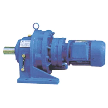
Advantages of Using a Cycloidal Gearbox
Cycloidal gearboxes offer several advantages that make them well-suited for various applications:
- High Torque Density: Cycloidal gearboxes provide a high torque output relative to their size and weight. This makes them ideal for applications where space is limited, and high torque is required.
- Compact Design: The unique arrangement of cycloidal pins and lobed profiles results in a compact gearbox design. This is advantageous when dealing with constrained installation spaces.
- Smooth and Precise Motion: Cycloidal motion generates smooth and controlled movement, making these gearboxes suitable for applications requiring accurate positioning, such as robotics and automation.
- High Shock Load Capacity: The multiple points of contact between the cycloidal pins and the lobes distribute the load, allowing cycloidal gearboxes to handle sudden shocks and overloads effectively.
- Backlash Elimination: Cycloidal gearboxes exhibit minimal backlash due to the nature of their motion. This is beneficial in applications where precise motion reversal is crucial.
- High Efficiency: The rolling contact between the pins and lobes contributes to efficient power transmission, resulting in relatively high efficiency levels.
- Reduced Wear and Noise: The rolling motion in cycloidal gearboxes leads to reduced wear on components, resulting in lower maintenance requirements and quieter operation.
- Versatility: Cycloidal gearboxes can handle a wide range of ratios and speeds, making them suitable for various industrial and automation applications.
Due to these advantages, cycloidal gearboxes are commonly used in robotics, automation, packaging machinery, conveyors, and other applications where compactness, 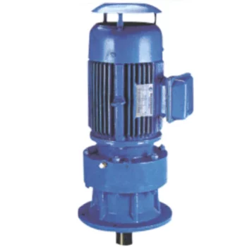
Noise and Vibration Considerations in Cycloidal Gearboxes
Cycloidal gearboxes are generally known for their smooth and quiet operation. However, like any mechanical system, they can still exhibit some level of noise and vibration. Here are the key factors to consider:
- Gear Design: The unique rolling contact design of cycloidal gears contributes to their relatively low noise levels. The teeth engagement is gradual and continuous, reducing impact forces and noise.
- Lubrication: Proper lubrication is essential to minimize friction and noise. Using high-quality lubricants and maintaining proper lubrication levels can help reduce noise and vibration in cycloidal gearboxes.
- Precision Manufacturing: Precise manufacturing processes and tight tolerances can help minimize irregularities in gear meshing, which can contribute to noise and vibration.
- Load Distribution: Proper load distribution among multiple lobes in the cycloidal mechanism can help prevent localized stress concentrations that could lead to vibrations and noise.
- Bearing Quality: High-quality bearings can contribute to smooth operation and reduce vibrations that could be transmitted to the gearbox housing.
- Mounting and Installation: Proper mounting and alignment of the gearbox are impor
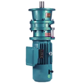
Suitability of Cycloidal Gearboxes for High-Torque Applications
Cycloidal gearboxes are well-suited for high-torque applications due to their unique design and mechanical advantages. Here’s why they are suitable:
- Multiple Engagement Points: Cycloidal gearboxes have multiple teeth in contact at any given moment, distributing the load over a larger area. This reduces wear and stress on individual teeth, making them capable of handling high torque.
- High Load-Carrying Capacity: The design of the cycloidal mechanism, with its large number of pins and rollers, provides high load-carrying capacity. This makes them capable of transmitting significant torque without failure.
- Tight Tolerances: The precision and tight tolerances in the construction of cycloidal gearboxes ensure smooth and efficient power transmission even under heavy loads.
- Compact Design: Cycloidal gearboxes achieve high torque in a relatively compact size. This is particularly advantageous in applications where space is limited.
- High Gear Ratio: Cycloidal gearboxes can achieve high gear ratios, allowing them to convert lower input speeds into higher output torque, which is essential in high-torque applications.
These factors make cycloidal gearboxes a reliable choice for various high-torque applications across industries such as heavy machinery, robotics, material handling, and more.
tant to ensure that it operates smoothly and without excessive vibrations.
While cycloidal gearboxes are designed to minimize noise and vibration, it’s important to consider the specific application, environmental conditions, and operating parameters. Regular maintenance, proper lubrication, and selecting the appropriate gearbox size and type can all contribute to reducing noise and vibration levels in cycloidal gearboxes.
high torque, and precise motion are critical.


editor by CX 2023-08-22
China supplier Rated Output Torque 1140-2000nm Helical Gear High Precision Cycloidal Gearbox for Pipe Bender cycloidal gearboxes
Product Description
Product Description
Rated output torque 1140-2000Nm Helical gear high precision cycloidal gearbox for pipe bender
Helical gear high precision cycloidal gearbox is a new generation of practical products independently developed by our company:
Low noise: less than 65db.
Low back clearance: up to 3 arc minutes in a CZPT and 5 arc minutes in a double stage.
High torque: higher than the standard planetary reducer torque.
High stability: high strength alloy steel, the whole gear after hardening treatment, not only the surface hard substitution.
High deceleration ratio: Modular design, planetary gearbox can be interlinked.
Helical gear high precision cycloidal gearbox characteristic:
1.Planetary reducer manufacturer-Fubao Electromechanical Technology adopts an integrated planetary carrier and output shaft, which can provide better torsional rigidity. After precision machining, the gear set is not easy to eccentric, which can reduce interference, reduce wear and noise, and at the same time use a large The bearings are arranged with a wide span to distribute the load of the bearings, and once again strengthen the torque rigidity and radial load capacity of the gearbox. The output cover is made of aluminum alloy, which provides better heat dissipation capability for the product, so that the reducer produced by Fubao Electromechanical Technology can play an excellent role in the field of mechanical tools.
2.The planetary gear set is specially made of alloy steel. First, it undergoes quenching and tempering heat treatment to make the material hardness reach HRC30 degrees, and then undergoes nitriding surface treatment to HV860, so that the product has the characteristics of high surface hardness and high toughness in the center, and achieves the best product strength and service life. optimization.
3.The input shaft and the motor output shaft are connected by a bolted structure, with a round shaft seal design, and through dynamic balance analysis, it can ensure that there is no eccentric load at high speeds. After reducing unnecessary radial force, it can effectively Reduce the load on the motor side.
4.The material of the input cover/motor connection seat is made of aluminum alloy, which can provide better heat dissipation effect, and then provide good concentricity and verticality through professional lathe processing, so that the product can be stably combined with various motors, reducing the damage caused by insufficient precision. Unnecessary axial radial force makes the product have a longer life cycle.
| WAB series parameters | Model number | WAB042 | WAB60 | WAB090 | WAB115 | WAB140 | WAB180 | WAB220 |
| Rated output torque | 14-22 | 23-60 | 48-160 | 140-330 | 342-650 | 520-1200 | 1140-2000 | |
| Reduction ratio | L1: 3, 4, 5, 6, 7, 8, 9, 10 L2: 15, 20, 25, 30, 35, 40, 50, 70, 80, 100 | |||||||
| Planetary gear backlash | L1: P0≤1 P1≤3 P2≤5 L2: P0≤3 P1≤5 P2≤7 | |||||||
Detailed Photos
Product Details
Other products
Product Advantage
Compared with other reduction machines, planetary gear reduction machines have high rigidity, high precision (single stage can be achieved within 1 point), high transmission efficiency (single stage in 97-98%), high torque/volume ratio, lifetime maintenance free and other characteristics.
Because of these characteristics, planetary gear reducer is mostly installed on the stepper motor and servo motor, used to reduce speed, increase torque, matching inertia.
Company Profile
Factory Display
Q: Speed reducer grease replacement time
A: When sealing appropriate amount of grease and running reducer, the standard replacement time is 20000 hours according to the aging condition of the grease. In addition, when the grease is stained or used in the surrounding temperature condition (above 40ºC), please check the aging and fouling of the grease, and specify the replacement time.
Q: Delivery time
A: Fubao has 2000+ production base, daily output of 1000+ units, standard models within 7 days of delivery.
Q: Reducer selection
A: Fubao provides professional product selection guidance, with higher product matching degree, higher cost performance and higher utilization rate.
Q: Application range of reducer
A: Fubao has a professional research and development team, complete category design, can match any stepping motor, servo motor, more accurate matching.
|
Shipping Cost:
Estimated freight per unit. |
To be negotiated |
|---|
| Application: | Motor, Machinery, Agricultural Machinery, Mechanical Equipment |
|---|---|
| Hardness: | Hardened Tooth Surface |
| Installation: | Vertical Type |
| Customization: |
Available
| Customized Request |
|---|
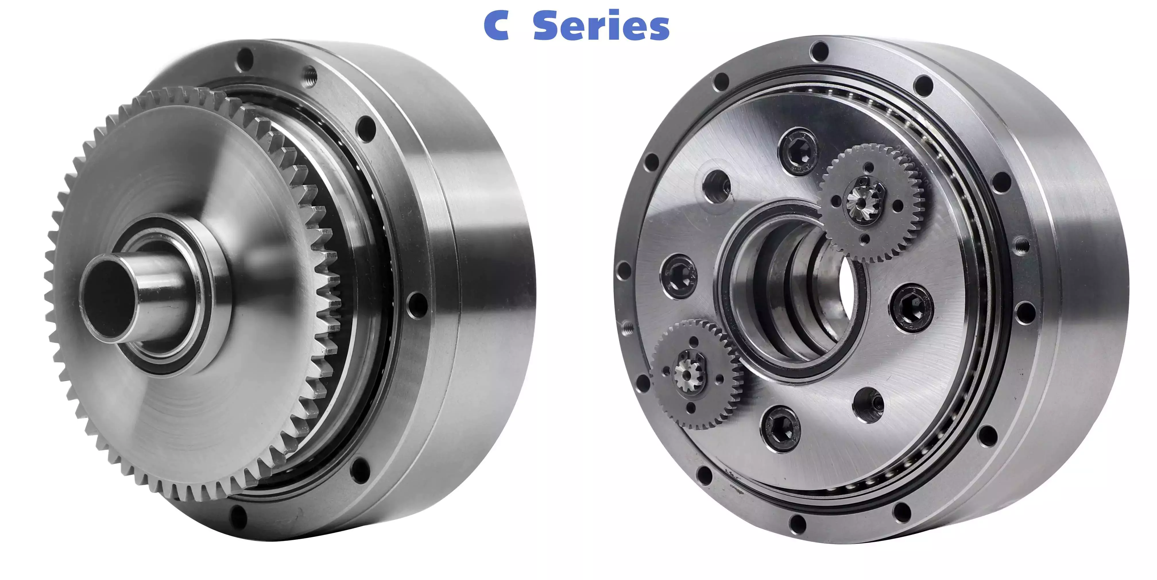
The Basics of a Cyclone Gearbox
Besides being compact, cycloidal speed reducers also offer low backlash and high ratios. Because of the small size of the drive, they are ideal for applications where space is a problem.
Involute gear tooth profile
Almost all gears use an involute gear tooth profile. This profile has a single curve, which means that the gear teeth do not have to be aligned closely with each other. This profile is smooth and can be manufactured easily.
Cycloid gears have a combination of epicycloid and hypocycloid curves. This makes them stronger than involute gear teeth. However, they can be more expensive to manufacture. They also have larger reduction ratios. They transmit more power than involute gears. Cycloid gears can be found in clocks.
When designing a gear, you need to consider several factors. Some of these include the number of teeth, the tooth angle and the lubrication type. Having a gear tooth that is not perfectly aligned can result in transmission error, noise and vibration.
The tooth profile of an involute gear is usually considered the best. Because of this, it is used in a wide variety of gears. Some of the most common applications for this profile are power transmission gears. However, this profile is not the best for every application.
Cycloid gears require more complex manufacturing processes than involute gear teeth. This can cause a larger tooth cost. Cycloid gears are used for less noisy applications.
Cycloid gears also transmit more power than involute gears. This can cause problems if the radii change tangentially. However, the shape is more simple than involute gears. Involute gears can handle centre sifts better.
Cycloid gears are less susceptible to transmission error. Cycloid gears have a convex surface, which makes them stronger than involute teeth. Cycloid gears also have a larger reduction ratio than involute gears. Cycloid teeth do not interfere with the mating teeth. However, they have a smaller number of teeth than involute teeth.
Rotation on the inside of the reference pitch circle of the pins
Whether a cycloidal gearbox is designed for stationary or rotating applications, the fundamental law of gearing must be observed: The ratio of angular velocities must be constant. This requires the rotation on the inside of the reference pitch circle of the pins to be constant. This is achieved through a series of cycloidal teeth, which act like tiny levers to transmit motion.
A cycloidal disc has N lobes which are rotated by three lobes per rotation around N pins. The number of lobes on a cycloidal disc is a significant factor in determining the transmission ratio.
A cycloidal disc is driven by an eccentric input shaft which is mounted to an eccentric bearing within an output shaft. As the input shaft rotates, the cycloidal disc moves around the pins of the pin disc.
The drive pin rotates at a 40 deg angle while the cycloidal disc rotates on the inside of the reference pitch circle of pins. As the drive pin rotates, it will slow the output motion. This means that the output shaft will complete only three revolutions with the input shaft, as opposed to nine revolutions with the input shaft.
The number of teeth on a cycloidal disc must be small compared to the number of surrounding pins. The disc must also be constructed with an eccentric radius. This will determine the size of the hole which will be required for the pin to fit between the pins.
When the input shaft is turned, the cycloidal disc will rotate on the inside of the reference pitch circle of roller pins. This will then transmit motion to the output shaft. The output shaft is supported by two bearings in an output housing. This design has low wear and torsional stiffness.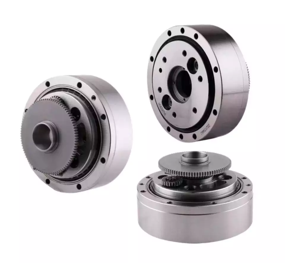
Transmission ratio
Choosing the right transmission ratio of cycloidal gearbox isn’t always easy. You might need to know the size of your gearbox before you can make an educated choice. You may also need to refer to the product catalog for guidance. For example, CZPT gearboxes have some unique ratios.
A cycloidal gear reducer is a compact and high-speed torque transmission device that reverses the direction of angular movement of the follower shaft. It consists of an eccentric cam positioned inside a cycloidal disc. Pin rollers on the follower shaft fit into matching holes in the cycloidal disc. In the process, the pins slide around the holes, in response to wobbling motion. The cycloidal disc is also capable of engaging the internal teeth of a ring-gear housing.
A cycloidal gear reducer can be used in a wide variety of applications, including industrial automation, robotics and power transmissions on boats and cranes. A cycloidal gear reducer is ideally suited for heavy duty applications with large payloads. They require specialized manufacturing processes, and are often used in equipment with precise output and high efficiency.
The cycloidal gear reducer is a relatively simple structure, but it does require some special tools. Cycloid gear reducers are also used to transmit torque, which is one of the reasons they are so popular in automation. Using a cycloidal gear reducer is a good choice for applications that require higher efficiency and lower backlash. It is also a good choice for applications where size is a concern. Cycloid gears are also a good choice for applications where high speed and high torque are required.
The transmission ratio of cycloidal gearbox is probably the most important function of a gearbox. You need to know the size of your gearbox and the type of gears it contains in order to make the right choice.
Vibration reduction
Considering the unique dynamics of a cycloidal gearbox, vibration reduction measures are required for a smooth operation. These measures can also help with the detection of faults.
A cycloidal gearbox is a gearbox with an eccentric bearing that rotates the center of the gears. It shares torque load with five outer rollers at any given time. It can be applied in many applications. It is a relatively inexpensive asset. However, if it fails, it can have significant economic impacts.
A typical input/output gearbox consists of a ring plate and two cranks mounted on the input shaft. The ring plate rotates when the input shaft rotates. There are two bearings on the output shaft.
The ring plate is a major noise source because it is not balanced. The cycloidal gear also produces noise when it meshes with the ring plate. This noise is generated by structural resonance. Several studies have been performed to solve this problem.
However, there is not much documented work on the condition monitoring of cycloidal gearboxes. In this article, we will introduce modern techniques for vibration diagnostics.
A cycloidal gearbox with a reduced reduction ratio has higher induced stresses in the cycloidal disc. In this case, the size of the output hole is larger and more material is removed from the cycloidal disc. This increase in the disc’s stresses leads to higher vibration amplitudes.
The load distribution along the width of the gear is an important design criterion. Using different gear profiles can help to optimize the transmission of torque. The contact stress of the cycloidal disc can also be investigated.
To determine the amplitude of the noise, the frequency of the gear mesh is multiplied by the shaft rate. If the RPM is relatively stable, the frequency can be used as a measure of magnitude. However, this is only accurate at close to failure.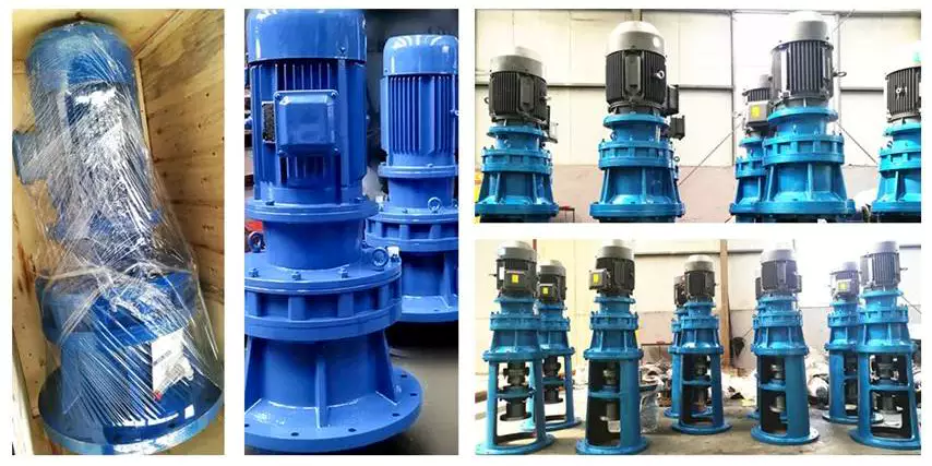
Comparison with planetary gearboxes
Several differences exist between cycloidal gearboxes and planetary gearboxes. They are related to gear geometry and manufacturing processes. Among them, there are:
– The output shaft of a cycloidal gearbox has a larger torque than the input shaft. The rotational speed of the output shaft is lower than the input shaft.
– The cycloid gear disc rotates at variable velocity, while the planetary gear has a fixed speed. Consequently, the cycloid disc and output flange transmission accuracy is lower than that of the planetary gears.
– The cycloidal gearbox has a larger gripping area than the planetary gear. This is an advantage of the cycloidal gearbox in that it can handle larger loads.
– The cycloid profile has a significant impact on the quality of contact meshing between the tooth surfaces. The width of the contact ellipses increases by 90%. This is a result of the elimination of undercuts of the lobes. In this way, the contact force on the cycloid disc is decreased significantly.
– The cycloid drive has lower backlash and high torsional stiffness. This allows a cycloidal drive to be more stable against shock loads. The cycloid drive is also a compact design, which is ideally suited for applications with large transmission ratios.
– The output hub of the cycloid gearbox has movable pins and rollers. These components are attached to the ring gear in the outer gearbox. The output shaft is also turned by the planet carrier. The output hub of the cycloid system is composed of two parts: the ring gear and the output flange.
– The input shaft of a cycloidal gearbox is connected to a servomotor. The input shaft is a cylindrical element that is fixed to the planet carrier.

editor by CX 2023-05-11