Product Description
Detailed Photos
Features of S series reducer
The same model can be equipped with motors of various powers. It is easy to realize the combination and connection between various models.
The transmission efficiency is high, and the single reducer efficiency is up to 96%. three
The transmission ratio is subdivided and the range is wide. The combined model can form a large transmission ratio and low output speed.
The installation forms are various, and can be installed with any foot, B5 flange or B4 flange. The foot mounting reducer has 2 machined foot mounting planes.
Helical gear and worm gear combination, compact structure, large reduction ratio.
Installation mode: foot installation, hollow shaft installation, flange installation, torque arm installation, small flange installation.
Input mode: motor direct connection, motor belt connection or input shaft, connection flange input.
Average efficiency: reduction ratio 7.5-69.39 is 77%; 70.43-288 is 62%; The S/R combination is 57%.
S57 SF57 SA57 SAF57 S series helical worm gear box speed reducer 0.18kw 0.25kw 0.37kw 0.55kw 0.75kw 1.1kw 1.5kw 2.2kw 3kw, max. permissible torque up to 300Nm, transmission ratios from 10.78 to 196.21. Mounting mode: foot mounted, flange mounted, short flange mounted, torque arm mounted. Output shaft: CHINAMFG shaft, hollow shaft (with key, with shrink disc and with involute spline).
Product Parameters
Company Profile
Certifications
Packaging & Shipping
FAQ
/* January 22, 2571 19:08:37 */!function(){function s(e,r){var a,o={};try{e&&e.split(“,”).forEach(function(e,t){e&&(a=e.match(/(.*?):(.*)$/))&&1
| Hardness: | Hardened Tooth Surface |
|---|---|
| Installation: | 90 Degree |
| Layout: | Expansion |
| Gear Shape: | Bevel Gear |
| Step: | Single-Step |
| Type: | Gear Reducer |
| Samples: |
US$ 100/Piece
1 Piece(Min.Order) | |
|---|
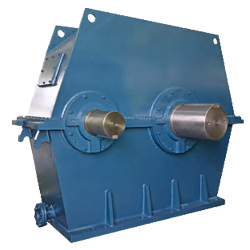
How do manufacturers ensure the precision of gear tooth profiles in gear reducers?
Manufacturers employ several techniques to ensure the precision of gear tooth profiles in gear reducers, which is crucial for optimal performance and efficiency:
1. Precision Machining: Gear teeth are typically machined using advanced CNC (Computer Numerical Control) machines that can achieve high levels of accuracy and repeatability. This ensures consistent gear tooth profiles across multiple components.
2. Quality Control Measures: Rigorous quality control processes, such as dimensional inspections and profile measurements, are performed at various stages of manufacturing to verify that gear tooth profiles meet the required specifications.
3. Tooth Profile Design: Engineers use specialized software and simulation tools to design gear tooth profiles with precise involute shapes and accurate dimensions. These designs are then translated into machine instructions for manufacturing.
4. Material Selection: High-quality materials with excellent wear resistance and dimensional stability are chosen to minimize the potential for deformation or inaccuracies during machining and operation.
5. Heat Treatment: Heat treatment processes, such as carburizing and quenching, are applied to enhance the surface hardness and durability of gear teeth, reducing the risk of wear and deformation over time.
6. Tooth Grinding and Finishing: After initial machining, gear teeth often undergo precision grinding and finishing processes to achieve the desired tooth profile accuracy and surface finish.
7. Post-Processing Inspection: Gear tooth profiles are inspected again after manufacturing processes to verify that the final components meet the specified tolerances and performance criteria.
8. Computer-Aided Manufacturing (CAM): CAM software is used to generate tool paths and machining instructions, enabling precise control over tool movements and material removal during gear manufacturing.
By combining these techniques and leveraging advanced manufacturing technologies, manufacturers can achieve the necessary precision in gear tooth profiles, resulting in reliable and efficient gear reducers for various industrial applications.
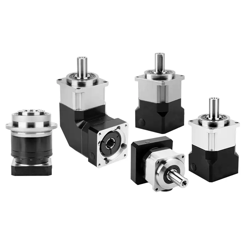
Can gear reducers be used for both speed reduction and speed increase?
Yes, gear reducers can be utilized for both speed reduction and speed increase, depending on their design and arrangement. The functionality to either decrease or increase rotational speed is achieved by altering the arrangement of gears within the gearbox.
1. Speed Reduction: In speed reduction applications, a gear reducer is designed with gears of different sizes. The input shaft connects to a larger gear, while the output shaft is connected to a smaller gear. As the input shaft rotates, the larger gear turns the smaller gear, resulting in a decrease in output speed compared to the input speed. This configuration provides higher torque output at a lower speed, making it suitable for applications that require increased force or torque.
2. Speed Increase: For speed increase, the gear arrangement is reversed. The input shaft connects to a smaller gear, while the output shaft is connected to a larger gear. As the input shaft rotates, the smaller gear drives the larger gear, resulting in an increase in output speed compared to the input speed. However, the torque output is lower than that of speed reduction configurations.
By choosing the appropriate gear ratios and arrangement, gear reducers can be customized to meet specific speed and torque requirements for various industrial applications. It’s important to select the right type of gear reducer and configure it correctly to achieve the desired speed reduction or speed increase.
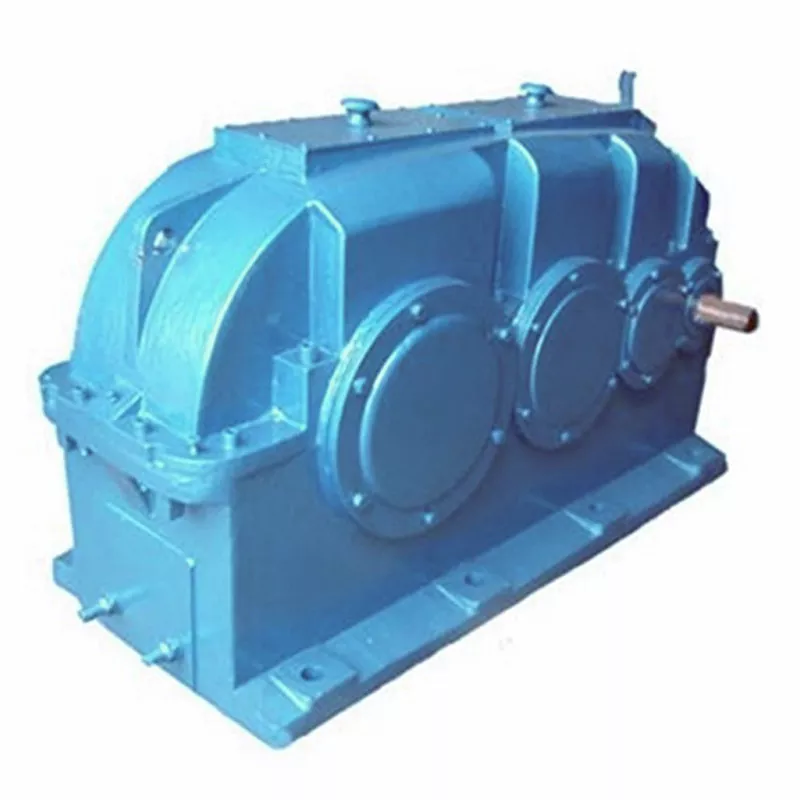
How do gear reducers contribute to speed reduction and torque increase?
Gear reducers play a crucial role in mechanical systems by achieving speed reduction and torque increase through the principle of gear ratios. Here’s how they work:
Gear reducers consist of multiple gears with different sizes, known as gear pairs. These gears are meshed together, and their teeth interlock to transmit motion and power. The gear ratio is determined by the ratio of the number of teeth on the input gear (driver) to the number of teeth on the output gear (driven).
Speed Reduction: When a larger gear (output gear) is driven by a smaller gear (input gear), the output gear rotates at a slower speed than the input gear. This reduction in speed is proportional to the gear ratio. As a result, gear reducers are used to slow down the rotational speed of the output shaft compared to the input shaft.
Torque Increase: The interlocking teeth of gears create a mechanical advantage that allows gear reducers to increase torque output. When the input gear applies a force (torque) to the teeth, it is transmitted to the output gear with greater force due to the leverage provided by the larger diameter of the output gear. The torque increase is inversely proportional to the gear ratio and is essential for applications requiring high torque at lower speeds.
By selecting appropriate gear ratios and arranging gear pairs, gear reducers can achieve various speed reduction and torque multiplication factors, making them essential components in machinery and equipment where precise control of speed and torque is necessary.


editor by CX 2024-05-09
China best ZD Low Backlash High Torque Helical Gear Planetary Gearbox Speed Reducer for AGV, CNC Machine, Robot bevel gearbox
Product Description
Model Selection
Planetar y gearbox is a kind of reducer with wide versatility. The inner gear adopts low carbon alloy steel carburizing quenching and grinding or nitriding process. Planetary gearbox has the characteristics of small structure size, large output torque, high speed ratio, high efficiency, safe and reliable performance, etc. The inner gear of the planetary gearbox can be divided into spur gear and helical gear.
• Model Selection
Our professional sales representive and technical team will choose the right model and transmission solutions for your usage depend on your specific parameters.
• Drawing Request
If you need more product parameters, catalogues, CAD or 3D drawings, please contact us.
• On Your Need
We can modify standard products or customize them to meet your specific needs.
Range Of Planetary Gearbox
Other Products
Company Profile
/* January 22, 2571 19:08:37 */!function(){function s(e,r){var a,o={};try{e&&e.split(“,”).forEach(function(e,t){e&&(a=e.match(/(.*?):(.*)$/))&&1
| Application: | Motor, Machinery, Marine, Agricultural Machinery |
|---|---|
| Function: | Change Drive Torque, Speed Changing, Speed Reduction |
| Hardness: | Hardened Tooth Surface |
| Installation: | Vertical Type |
| Type: | Planetary Gear Box |
| Size: | 60mm-160mm |
| Samples: |
US$ 100/Piece
1 Piece(Min.Order) | |
|---|
| Customization: |
Available
| Customized Request |
|---|
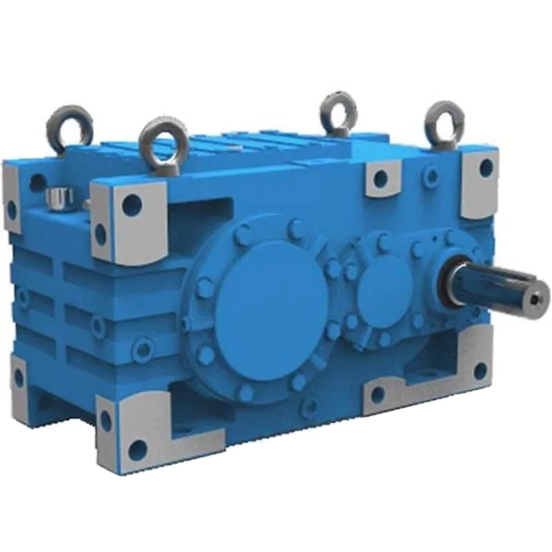
How do gear reducers contribute to energy efficiency in machinery and equipment?
Gear reducers play a significant role in enhancing energy efficiency in various machinery and equipment. Here’s how they contribute:
1. Speed Reduction: Gear reducers are commonly used to reduce the speed of the input shaft, allowing the motor to operate at a higher speed where it’s most efficient. This speed reduction helps match the motor’s optimal operating range, reducing energy consumption.
2. Torque Increase: Gear reducers can increase torque output while decreasing speed, enabling machinery to handle higher loads without the need for a larger, more energy-intensive motor.
3. Matching Load Requirements: By adjusting gear ratios, gear reducers ensure that the machinery’s output speed and torque match the load requirements. This prevents the motor from operating at unnecessary high speeds, saving energy.
4. Variable Speed Applications: In applications requiring variable speeds, gear reducers allow for efficient speed control without the need for continuous motor adjustments, improving energy usage.
5. Efficient Power Transmission: Gear reducers efficiently transmit power from the motor to the load, minimizing energy losses due to friction and inefficiencies.
6. Motor Downsizing: Gear reducers enable the use of smaller, more energy-efficient motors by converting their higher speed, lower torque output into the lower speed, higher torque needed for the application.
7. Decoupling Motor and Load Speeds: In cases where the motor and load speeds are inherently different, gear reducers ensure the motor operates at its most efficient speed while still delivering the required output to the load.
8. Overcoming Inertia: Gear reducers help overcome the inertia of heavy loads, making it easier for motors to start and stop, reducing energy consumption during frequent operation.
9. Precise Control: Gear reducers provide precise control over speed and torque, optimizing the energy consumption of machinery in processes that require accurate adjustments.
10. Regenerative Braking: In some applications, gear reducers can be used to capture and convert kinetic energy back into electrical energy during braking or deceleration, improving overall energy efficiency.
By efficiently managing speed, torque, and power transmission, gear reducers contribute to energy-efficient operation, reducing energy consumption, and minimizing the environmental impact of machinery and equipment.
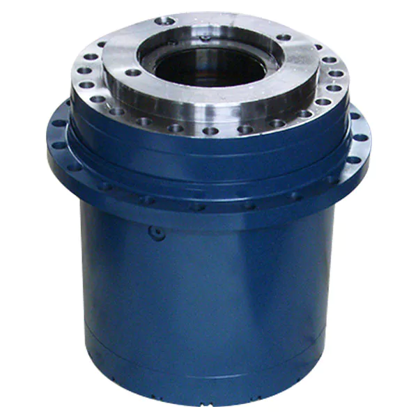
How do gear reducers ensure efficient power transmission and motion control?
Gear reducers play a vital role in ensuring efficient power transmission and precise motion control in various industrial applications. They achieve this through the following mechanisms:
- 1. Speed Reduction/Increase: Gear reducers allow you to adjust the speed between the input and output shafts. Speed reduction is essential when the output speed needs to be lower than the input speed, while speed increase is used when the opposite is required.
- 2. Torque Amplification: By altering the gear ratio, gear reducers can amplify torque from the input to the output shaft. This enables machinery to handle higher loads and provide the necessary force for various tasks.
- 3. Gear Train Efficiency: Well-designed gear trains within reducers minimize power losses during transmission. Helical and spur gears, for example, offer high efficiency by distributing load and reducing friction.
- 4. Precision Motion Control: Gear reducers provide precise control over rotational motion. This is crucial in applications where accurate positioning, synchronization, or timing is required, such as in robotics, CNC machines, and conveyor systems.
- 5. Backlash Reduction: Some gear reducers are designed to minimize backlash, which is the play between gear teeth. This reduction in play ensures smoother operation, improved accuracy, and better control.
- 6. Load Distribution: Gear reducers distribute the load evenly among multiple gear teeth, reducing wear and extending the lifespan of the components.
- 7. Shock Absorption: In applications where sudden starts, stops, or changes in direction occur, gear reducers help absorb and dampen shocks, protecting the machinery and ensuring reliable operation.
- 8. Compact Design: Gear reducers provide a compact solution for achieving specific speed and torque requirements, allowing for space-saving integration into machinery.
By combining these principles, gear reducers facilitate the efficient and controlled transfer of power, enabling machinery to perform tasks accurately, reliably, and with the required force, making them essential components in a wide range of industries.
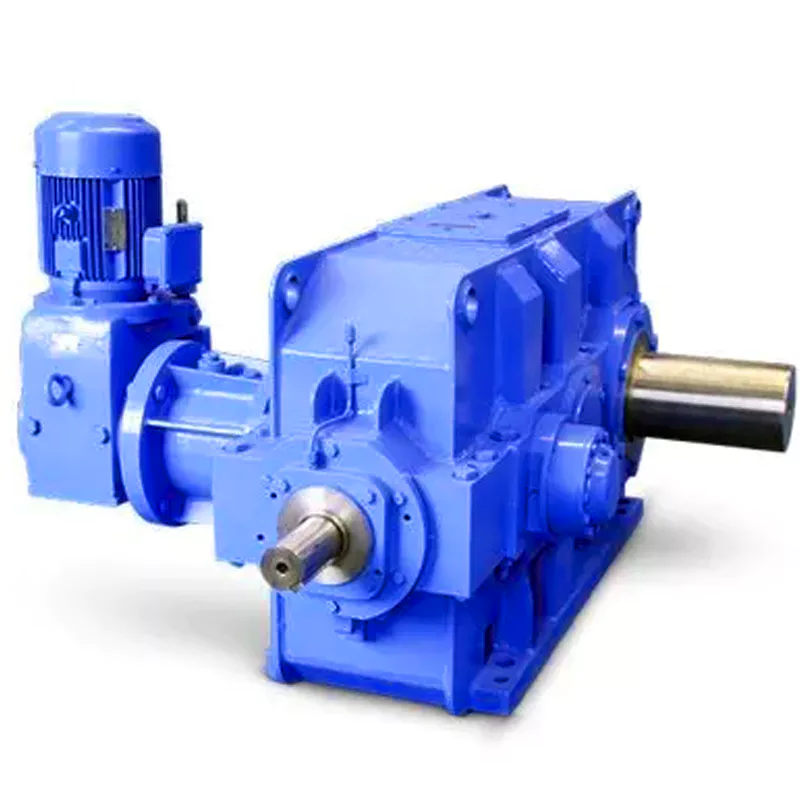
What are the benefits of using a gear reducer in industrial applications?
Gear reducers offer several benefits that make them indispensable in various industrial applications:
1. Speed Reduction: Gear reducers allow the reduction of high-speed input from motors or engines to lower, more usable output speeds for specific applications, ensuring proper equipment operation and safety.
2. Torque Increase: By leveraging the mechanical advantage of gear ratios, gear reducers can significantly increase torque output, enabling the handling of heavy loads and providing the necessary power for tasks such as lifting, conveying, and processing.
3. Precise Control: Gear reducers enable fine-tuning of rotational speed and torque, providing precise control over machinery and processes, which is crucial in industries like manufacturing, material handling, and robotics.
4. Shock Load Absorption: Gear reducers can absorb and dampen sudden shocks or changes in load, protecting both the machinery and connected components from abrupt forces that could otherwise lead to damage.
5. Versatility: With various gear types (e.g., spur, helical, worm) and designs, gear reducers can be tailored to different applications, including those requiring specific speed ratios, torque ranges, and environmental conditions.
6. Efficient Power Transmission: Gear reducers offer high mechanical efficiency, minimizing energy loss during power transmission, which is especially valuable in energy-conscious industries.
7. Compact Design: Gear reducers provide a compact solution for transmitting power and adjusting speeds, making them suitable for installations with space constraints.
8. Reliability and Longevity: Well-designed and properly maintained gear reducers can offer extended service life, contributing to reduced downtime and maintenance costs.
Overall, gear reducers enhance the performance, efficiency, and reliability of industrial equipment, making them essential components in a wide range of applications across various industries.


editor by CX 2024-04-30
China Custom Helical Shaft Mount Gear Unit Gearbox Ratio5 13 20 Smr Series Shaft Mounted Speed Reducer bevel gearbox
Product Description
Product Description
Helical shaft mount gear unit gearbox ratio5 13 20 SMR series shaft mounted speed reducer
1. Product Characteristics
(1) Strong alloy steel, hardened, ground on journals, gear seatings and extensions, for maximum load and maximum torsional loads. Generous size shaft keys for shock loading and conform to iso standards.
(2) Standard or alternative hubs with metric bores are available to suit international standard shaft diameters.
(3) Strong alloy materials for high load capacity, carburizing and quenching, ground profile(some intermediate pinions are shaved) CHINAMFG tooth profile, 98% efficiency for per stage, smooth quiet operation with several teeth in mesh.
(4) Close grain cast iron construction, excellent vibration dampening & shock resistance features, precision bored and dowelled to ensure accurate in-line assembly.
(5) Eliminates the need for critical tightening of torque arm bolts, controls position of standard torque arm mounting within recommended.
(6) Bearings are adequately proportioned and conform to iso dimension plan, readily available world-wide. Oil seals are double garter spring type, ensuring effective oil sealing.
(7) Self sealing intermediate cover plates, to standard iso housing dimensions.
(8) Alternative parts, anti-run back device, are available on bothl 13:1 and 20:1 ratio units and do not recommend for 5:1 units.
(9) To adjust the install space location of reducer and the elasticity of belt.
The models of SMR shafted mounted gearbox: B,C,D,E,F,G,H,J series shaft mounted gearbox
Detailed Photos
Product Parameters
| Rated Power |
Gear Arrangement | Output Speed | Ratio | Back-stop |
| 0.29KW~134KW | Helical Hardened Gearbox | 10~400r/min | I=1/5,1/13,1/20 | Alternative parts, Anti-runback device |
Packaging & Shipping
Company Profile
Our Advantages
Our Services:
| Pre-sale services | 1. Select equipment model. |
| 2.Design and manufacture products according to clients’ special requirement. | |
| 3.Train technical personal for clients | |
| Services during selling | 1.Pre-check and accept products ahead of delivery. |
| 2. Help clients to draft solving plans. | |
| After-sale services | 1.Assist clients to prepare for the first construction scheme. |
| 2. Train the first-line operators. | |
| 3.Take initiative to eliminate the trouble rapidly. | |
| 4. Provide technical exchanging. |
FAQ
1.Q:What kinds of gearbox can you produce for us?
A:Main products of our company: UDL series speed variator,RV series worm gear reducer, ATA series shaft mounted gearbox, X,B series gear reducer,
P series planetary gearbox and R, S, K, and F series helical-tooth reducer, more
than 1 hundred models and thousands of specifications
2.Q:Can you make as per custom drawing?
A: Yes, we offer customized service for customers.
3.Q:What is your terms of payment ?
A: 30% Advance payment by T/T after signing the contract.70% before delivery
4.Q:What is your MOQ?
A: 1 Set
If you have any demand for our products please feel free to contact me.
| Application: | Machinery, Industry |
|---|---|
| Hardness: | Hardened |
| Installation: | Horizontal Type |
| Layout: | Parallel |
| Gear Shape: | Helical |
| Step: | Double-Step |
| Customization: |
Available
| Customized Request |
|---|
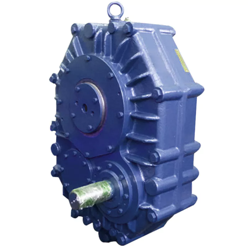
Are there any disadvantages or limitations to using gear reducer systems?
While gear reducer systems offer numerous advantages, they also come with certain disadvantages and limitations that should be considered during the selection and implementation process:
1. Size and Weight: Gear reducers can be bulky and heavy, especially for applications requiring high gear ratios. This can impact the overall size and weight of the machinery or equipment, which may be a concern in space-constrained environments.
2. Efficiency Loss: Despite their high efficiency, gear reducers can experience energy losses due to friction between gear teeth and other components. This can lead to a reduction in overall system efficiency, particularly in cases where multiple gear stages are used.
3. Cost: The design, manufacturing, and assembly of gear reducers can involve complex processes and precision machining, which can contribute to higher initial costs compared to other power transmission solutions.
4. Maintenance: Gear reducer systems require regular maintenance, including lubrication, inspection, and potential gear replacement over time. Maintenance activities can lead to downtime and associated costs in industrial settings.
5. Noise and Vibration: Gear reducers can generate noise and vibrations, especially at high speeds or when operating under heavy loads. Additional measures may be needed to mitigate noise and vibration issues.
6. Limited Gear Ratios: While gear reducers offer a wide range of gear ratios, there may be limitations in achieving extremely high or low ratios in certain designs.
7. Temperature Sensitivity: Extreme temperatures can affect the performance of gear reducer systems, particularly if inadequate lubrication or cooling is provided.
8. Shock Loads: While gear reducers are designed to handle shock loads to some extent, severe shock loads or abrupt changes in torque can still lead to potential damage or premature wear.
Despite these limitations, gear reducer systems remain widely used and versatile components in various industries, and their disadvantages can often be mitigated through proper design, selection, and maintenance practices.
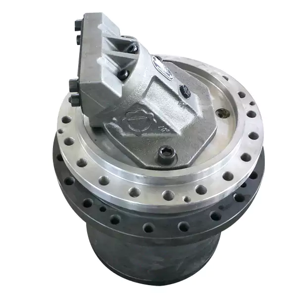
What factors should be considered when selecting the right gear reducer?
Choosing the appropriate gear reducer involves considering several crucial factors to ensure optimal performance and efficiency for your specific application:
- 1. Torque and Power Requirements: Determine the amount of torque and power your machinery needs for its operation.
- 2. Speed Ratio: Calculate the required speed reduction or increase to match the input and output speeds.
- 3. Gear Type: Select the appropriate gear type (helical, bevel, worm, planetary, etc.) based on your application’s torque, precision, and efficiency requirements.
- 4. Mounting Options: Consider the available space and the mounting configuration that suits your machinery.
- 5. Environmental Conditions: Evaluate factors such as temperature, humidity, dust, and corrosive elements that may impact the gear reducer’s performance.
- 6. Efficiency: Assess the gear reducer’s efficiency to minimize power losses and improve overall system performance.
- 7. Backlash: Consider the acceptable level of backlash or play between gear teeth, which can affect precision.
- 8. Maintenance Requirements: Determine the maintenance intervals and procedures necessary for reliable operation.
- 9. Noise and Vibration: Evaluate noise and vibration levels to ensure they meet your machinery’s requirements.
- 10. Cost: Compare the initial cost and long-term value of different gear reducer options.
By carefully assessing these factors and consulting with gear reducer manufacturers, engineers and industry professionals can make informed decisions to select the right gear reducer for their specific application, optimizing performance, longevity, and cost-effectiveness.
What industries and machinery commonly utilize gear reducers?
Gear reducers are widely used across various industries and types of machinery for torque reduction and speed control. Some common industries and applications include:
- 1. Manufacturing: Gear reducers are used in manufacturing equipment such as conveyors, mixers, and packaging machines to control speed and transmit power efficiently.
- 2. Automotive: They are utilized in vehicles for applications like power transmission in transmissions and differentials.
- 3. Aerospace: Gear reducers are used in aircraft systems, including landing gear mechanisms and engine accessories.
- 4. Robotics and Automation: They play a crucial role in robotic arms, CNC machines, and automated production lines.
- 5. Mining and Construction: Gear reducers are used in heavy machinery like excavators, bulldozers, and crushers for power transmission and torque multiplication.
- 6. Energy and Power Generation: Wind turbines, hydroelectric generators, and other power generation equipment use gear reducers to convert rotational speed and transmit power.
- 7. Marine and Shipbuilding: They are used in ship propulsion systems, steering mechanisms, and anchor handling equipment.
- 8. Material Handling: Gear reducers are essential in conveyor systems, elevators, and hoists for controlled movement of materials.
- 9. Food and Beverage: They find applications in food processing equipment like mixers, grinders, and packaging machines.
- 10. Paper and Pulp: Gear reducers are used in machinery for pulp processing, paper production, and printing.
These examples represent just a fraction of the industries and machinery that benefit from the use of gear reducers to optimize power transmission and achieve the desired motion characteristics.


editor by CX 2023-12-04
China factory F Helical Motor Gearbox Transmission Gear Speed Reducer bevel gearbox
Product Description
F Series Helical Motor Gearbox Transmission Gear Speed Reducer. Helical gearbox series not only has higher transmission efficiency and loading capability than those of single-stage worm wheel transmission, but also reduces space. Moreover, under the close volume, the series can obtain higher transmission ratio and is more favorable for equipment setting. This product can be combined with various reducers to meet different requirements. S series with self-lock function
Energy Efficiency: Leveraging the advantages of high efficiency of helical gears and smooth transmission of worm gears, the reducer performs with outstanding stability and efficiency is above 90%
Loading Capacity: Available with power ranges from 0.12KW to 37KW, depending on different requirements and applications.
Installation Flexibility: All models are designed for a choice of mounting position M1-M6 specified by customers.
RICHMAN UNIVERSAL SOURCING CO LIMITED is located in HangZhou ZheJiang . With more than 20 years experience in gear transmission area, we have our owned factory and product lines. Worm reducer (WP series; RV series; VF series), screw jack reducer (WSH series) and helical gearbox (K,S,R,F series) are current mainly products. Strict and precision quality control procedure makes the final products meet demands of our customers.
We try to develop different markets, cooperate with kinds of customers, which can makes us keep moving forward, keep innovative and international vision. Richman Universal Sourcing is your best partner of transmission resolutions.
| Application: | Motor, Machinery |
|---|---|
| Function: | Change Drive Torque, Change Drive Direction, Speed Reduction |
| Layout: | Coaxial |
| Hardness: | Hardened Tooth Surface |
| Installation: | Vertical Type |
| Step: | Three-Step |
| Customization: |
Available
| Customized Request |
|---|

How do gear reducers contribute to energy efficiency in machinery and equipment?
Gear reducers play a significant role in enhancing energy efficiency in various machinery and equipment. Here’s how they contribute:
1. Speed Reduction: Gear reducers are commonly used to reduce the speed of the input shaft, allowing the motor to operate at a higher speed where it’s most efficient. This speed reduction helps match the motor’s optimal operating range, reducing energy consumption.
2. Torque Increase: Gear reducers can increase torque output while decreasing speed, enabling machinery to handle higher loads without the need for a larger, more energy-intensive motor.
3. Matching Load Requirements: By adjusting gear ratios, gear reducers ensure that the machinery’s output speed and torque match the load requirements. This prevents the motor from operating at unnecessary high speeds, saving energy.
4. Variable Speed Applications: In applications requiring variable speeds, gear reducers allow for efficient speed control without the need for continuous motor adjustments, improving energy usage.
5. Efficient Power Transmission: Gear reducers efficiently transmit power from the motor to the load, minimizing energy losses due to friction and inefficiencies.
6. Motor Downsizing: Gear reducers enable the use of smaller, more energy-efficient motors by converting their higher speed, lower torque output into the lower speed, higher torque needed for the application.
7. Decoupling Motor and Load Speeds: In cases where the motor and load speeds are inherently different, gear reducers ensure the motor operates at its most efficient speed while still delivering the required output to the load.
8. Overcoming Inertia: Gear reducers help overcome the inertia of heavy loads, making it easier for motors to start and stop, reducing energy consumption during frequent operation.
9. Precise Control: Gear reducers provide precise control over speed and torque, optimizing the energy consumption of machinery in processes that require accurate adjustments.
10. Regenerative Braking: In some applications, gear reducers can be used to capture and convert kinetic energy back into electrical energy during braking or deceleration, improving overall energy efficiency.
By efficiently managing speed, torque, and power transmission, gear reducers contribute to energy-efficient operation, reducing energy consumption, and minimizing the environmental impact of machinery and equipment.
What maintenance practices are essential for prolonging the lifespan of gear reducers?
Proper maintenance is crucial for extending the lifespan and ensuring optimal performance of gear reducers. Here are essential maintenance practices:
- 1. Lubrication: Regular lubrication of gear reducers is vital to reduce friction, wear, and heat generation. Use the recommended lubricant and follow the manufacturer’s guidelines for lubrication intervals.
- 2. Inspection: Routinely inspect gear reducers for signs of wear, damage, or leaks. Check for unusual noises, vibrations, or temperature increases during operation.
- 3. Alignment: Ensure proper alignment of the input and output shafts. Misalignment can lead to increased wear, noise, and reduced efficiency. Align the components according to the manufacturer’s specifications.
- 4. Cooling and Ventilation: Maintain proper cooling and ventilation to prevent overheating. Ensure that cooling fans and vents are clean and unobstructed.
- 5. Seal Maintenance: Inspect and replace seals as needed to prevent contaminants from entering the gear reducer. Contaminants can lead to accelerated wear and reduced performance.
- 6. Bolts and Fasteners: Regularly check and tighten bolts and fasteners to prevent loosening during operation, which can cause misalignment or component damage.
- 7. Replacing Worn Components: Replace worn or damaged components, such as gears, bearings, and seals, with genuine parts from the manufacturer.
- 8. Vibration Analysis: Conduct periodic vibration analysis to identify potential issues early. Excessive vibration can indicate misalignment or component wear.
- 9. Maintenance Records: Keep detailed maintenance records, including lubrication schedules, inspection dates, and component replacements. This helps track the history of the gear reducer and aids in future maintenance planning.
- 10. Training: Provide proper training to maintenance personnel on gear reducer maintenance and troubleshooting techniques.
By adhering to these maintenance practices, you can maximize the lifespan of your gear reducers, minimize downtime, and ensure reliable operation in your industrial processes.

What industries and machinery commonly utilize gear reducers?
Gear reducers are widely used across various industries and types of machinery for torque reduction and speed control. Some common industries and applications include:
- 1. Manufacturing: Gear reducers are used in manufacturing equipment such as conveyors, mixers, and packaging machines to control speed and transmit power efficiently.
- 2. Automotive: They are utilized in vehicles for applications like power transmission in transmissions and differentials.
- 3. Aerospace: Gear reducers are used in aircraft systems, including landing gear mechanisms and engine accessories.
- 4. Robotics and Automation: They play a crucial role in robotic arms, CNC machines, and automated production lines.
- 5. Mining and Construction: Gear reducers are used in heavy machinery like excavators, bulldozers, and crushers for power transmission and torque multiplication.
- 6. Energy and Power Generation: Wind turbines, hydroelectric generators, and other power generation equipment use gear reducers to convert rotational speed and transmit power.
- 7. Marine and Shipbuilding: They are used in ship propulsion systems, steering mechanisms, and anchor handling equipment.
- 8. Material Handling: Gear reducers are essential in conveyor systems, elevators, and hoists for controlled movement of materials.
- 9. Food and Beverage: They find applications in food processing equipment like mixers, grinders, and packaging machines.
- 10. Paper and Pulp: Gear reducers are used in machinery for pulp processing, paper production, and printing.
These examples represent just a fraction of the industries and machinery that benefit from the use of gear reducers to optimize power transmission and achieve the desired motion characteristics.


editor by CX 2023-10-18
China Best Sales New Type Hot Sale F Series Reducer Bevel Helical Gearbox Right Angle Gearbox for Plastic Extruder Cycloidal CZPT comer gearbox
Product Description
Product Description
Boqiang Drive F series parallel shaft in-line Helical gear motors Drive Reduction Gear Box replace bevel gear box reduction gear harmonic drive reducer
Technical parameters
| Ratio | 5.36-178.37 |
| Input power | 0.12-200KW |
| Output torque | 10-61900n.M |
| Output speed | 0.08-261rpm |
| Mounting type | Foot mounted, foot mounted with CHINAMFG shaft, output flange mounted, hollow shaft mounted, B5 flange mounted with hollow shaft, foot mounted with hollow shaft, B14 flange mounted with hollow shaft, foot mounted with splined hole, foot mounted with shrink disk, hollow shaft mounted with anti-torque arm. |
| Input Method | Flange input(P or SF), shaft input(AD), inline AC motor input, or AQA servo motor |
| Brake Release | HF-manual release(lock in the brake release position), HR-manual release(autom-atic braking position) |
| Thermistor | TF(Thermistor protection PTC thermisto) TH(Thermistor protection Bimetal swotc |
Specification
|
Model |
Shaft Dia. mm |
Horizontal Center Height mm |
External Flange Dia. mm |
Power |
Ratio (i) |
Nominal Torque (Nm) |
|
|
Solid Shaft |
Hollow Shaft |
||||||
|
F/FF/FA/FAF37 |
ф25 |
ф30 |
76 |
160 |
0.18-3 | 3.81-128.51 | 10-228 |
|
F/FF/FA/FAF47 |
ф30 |
ф35 |
77 |
200 |
0.18-3 | 9.08-189.39 | 126-393 |
|
F/FF/FA/FAF57 |
ф35 |
ф40 |
93 |
250 |
0.18-5.5 | 5.18-127.27 | 129-624 |
|
F/FF/FA/FAF67 |
ф40 |
ф40 |
97 |
250 |
0.18-5.5 | 4.21-228.99 | 105-871 |
|
F/FF/FA/FAF77 |
ф50 |
ф50 |
121 |
300 |
0.18-11 | 4.30-281.71 | 198-1654 |
|
F/FF/FA/FAF87 |
ф60 |
ф60 |
152 |
350 |
0.37-22 | 4.20-271.92 | 387-3018 |
|
F/FF/FA/FAF97 |
ф70 |
ф70 |
178 |
450 |
0.55-30 | 4.68-276.64 | 857-4049 |
|
F/FF/FA/FAF107 |
ф90 |
ф90 |
200 |
450 |
1.1-45 | 6.20-255.25 | 1391-7161 |
|
F/FF/FA/FAF127 |
ф110 |
ф100 |
236 |
550 |
4-90 | 4.63-172.33 | 1545-13426 |
|
F/FF/FA/FAF157 |
ф120 |
ф120 |
286 |
660 |
5.5-200 | 11.92-266.76 | 7900-2 0571 |
F series parallel shaft helical gear reduction motor has the following design:
1.F. Y .. Foot shaft extension installation parallel shaft helical gear reducer:
2.FA.. Y .. The base hollow shaft is provided with a parallel shaft helical gear reducer:
3.FAZ… Y .. The small flange hollow shaft is installed with the parallel shaft helical gear reducer
4.FF..Y .. Flange shaft extension type installation parallel shaft helical gear reducer
5.FAF.. Y .. The flanged hollow shaft is provided with a parallel shaft helical gear reducer
6. F(FA FF FAF FAZ).. P/SF. Connecting flange input type parallel shaft helical gear reducer
7.F(FA FF FAF FAZ).. AD .. Shaft input parallel shaft helical gear reducer
8.FA(FF F FAF FAZ)…R … Y. Combined parallel shaft helical gear reducer
Mounting poKition:
PoKition of the motor thermal box:
Input power rating and permissible torque:
Gear unit weight:
Photos of the factory area
ZHangZhoug Boqiang Transmission Co., Ltd. was established in 2002 and is a high-tech enterprise that integrates design, development, manufacturing, and operation, producing and selling reduction motors and power transmission equipment. The company is located in Oubei Town, HangZhoua County, at the forefront of national reform and opening up, known as the “Little Xihu (West Lake) Dis.” of HangZhou. Close to National Highway 104 and east to HangZhou International Airport and Xihu (West Lake) Dis. International Container Terminal; South to HangZhou Railway Station and Passenger Transport Center; There are also many national tourist attractions such as Yandang Mountain and Xihu (West Lake) Dis. River. With convenient transportation and unique geographical location, it is highly welcomed by domestic and foreign users.
Our company produces 12 series of helical gear reducers for various purposes, including shaft mounted helical gear reducers, helical bevel gear reducers, helical worm gear reducers, spiral bevel gear steering boxes, worm gear reducers, continuously variable transmissions, spiral elevators, and large gearboxes. The power coverage is 0.12-2000kw, with a reduction ratio of 1.25-30000. Various combinations, deformations, and specialized products can meet most industrial requirements. The R, K, F, and S series reducers adopt the modular design principle of unit structure, greatly reducing the types of components and inventory, and greatly shortening the delivery cycle. The components have strong universality and low maintenance costs.
Boqiang has a leading position in China in terms of technology level and product market share. The products are widely used in various fields such as metallurgy, light industry, packaging, medicine, petroleum, chemical industry, lifting and transportation, three-dimensional parking, printing and dyeing, elevators, wind power, etc. Boqiang Company has excellent performance. The transmission technology experts from the headquarters and numerous application engineers and after-sales service technicians from various regional offices provide you with rapid and comprehensive technical consultation and comprehensive services.
Looking back at the past and looking CHINAMFG to the future, Boqiang has always been on the way forward, constantly improving and surpassing itself with high-quality products and comprehensive services, and winning the favor of the market and customers. We are willing to work together with people of insight from all walks of life to create a more brilliant tomorrow.
Processing equipment
Testing equipment and quality control
Quality:Insist on Improvement,Strive for CHINAMFG With the development of equipment manufacturing indurstry,customer never satirsfy with the current quality of our products,on the contrary,wcreate the value of quality.
Quality policy:to enhance the overall level in the field of power transmission
Quality View:Continuous Improvement , pursuit of excellence
Quality Philosophy:Quality creates value
Product matching
Packaging And Transportation
FAQ
Q1: Are you trading company or manufacturer?
A: We are factory.
Q2: What kinds of gearbox can you produce for us?
A: Main products of our company: R, S, K, F series helical-tooth reducer, RV series worm gear reducer,H Series Parallel Shaft Helical Reduction Gear Box
Q3: Can you make as per custom drawing?
A: Yes, we offer customized service for customers.
Q4: Can we buy 1 pc of each item for quality testing?
A: Yes, we are glad to accept trial order for quality testing.
Q5: What information shall we give before placing a purchase order?
A: a) Type of the gearbox, ratio, input and output type, input flange, mounting position, and motor informationetc.
b) Housing color.
c) Purchase quantity.
d) Other special requirements.
Q6: How long is your delivery time?
A: Generally it is 5-10 days if the goods are in stock. or it is 15-20 days if the goods are not in stock.
Q7: What is your terms of payment ?
A: 30% Advance payment by T/T after signing the contract.70% before delivery
| Application: | Electric Cars, Machinery, Agricultural Machinery |
|---|---|
| Hardness: | Hardened Tooth Surface |
| Installation: | Horizontal Type |
| Customization: |
Available
| Customized Request |
|---|
.shipping-cost-tm .tm-status-off{background: none;padding:0;color: #1470cc}
|
Shipping Cost:
Estimated freight per unit. |
about shipping cost and estimated delivery time. |
|---|
| Payment Method: |
|
|---|---|
|
Initial Payment Full Payment |
| Currency: | US$ |
|---|
| Return&refunds: | You can apply for a refund up to 30 days after receipt of the products. |
|---|
Efficiency of Cycloidal Gearboxes in Power Transmission
Cycloidal gearboxes offer relatively high power transmission efficiency compared to other types of gearboxes. The efficiency of a cycloidal gearbox depends on various factors, including the design, quality of components, lubrication, and load conditions.
Typically, the power transmission efficiency of a cycloidal gearbox ranges from 85% to 95%. However, this can vary based on several factors:
- Number of Reduction Stages: Multi-stage cycloidal gearboxes may experience slightly lower efficiency due to multiple gear meshing interactions.
- Quality and Design: Well-designed and precision-manufactured cycloidal gearboxes tend to exhibit higher efficiency.
- Lubrication: Proper lubrication is crucial for reducing friction and enhancing efficiency. Insufficient or deteriorated lubrication can lead to efficiency losses.
- Load Conditions: Higher loads and torque levels can lead to higher friction and lower efficiency. Properly matching the gearbox to the application is essential.
Despite minor efficiency losses compared to some other gearbox types, the benefits of compactness, high torque density, and precise motion control often outweigh the efficiency considerations in many applications.
Noise and Vibration Considerations in Cycloidal Gearboxes
Cycloidal gearboxes are generally known for their smooth and quiet operation. However, like any mechanical system, they can still exhibit some level of noise and vibration. Here are the key factors to consider:
- Gear Design: The unique rolling contact design of cycloidal gears contributes to their relatively low noise levels. The teeth engagement is gradual and continuous, reducing impact forces and noise.
- Lubrication: Proper lubrication is essential to minimize friction and noise. Using high-quality lubricants and maintaining proper lubrication levels can help reduce noise and vibration in cycloidal gearboxes.
- Precision Manufacturing: Precise manufacturing processes and tight tolerances can help minimize irregularities in gear meshing, which can contribute to noise and vibration.
- Load Distribution: Proper load distribution among multiple lobes in the cycloidal mechanism can help prevent localized stress concentrations that could lead to vibrations and noise.
- Bearing Quality: High-quality bearings can contribute to smooth operation and reduce vibrations that could be transmitted to the gearbox housing.
- Mounting and Installation: Proper mounting and alignment of the gearbox are important to ensure that it operates smoothly and without excessive vibrations.
While cycloidal gearboxes are designed to minimize noise and vibration, it’s important to consider the specific application, environmental conditions, and operating parameters. Regular maintenance, proper lubrication, and selecting the appropriate gearbox size and type can all contribute to reducing noise and vibration levels in cycloidal gearboxes.
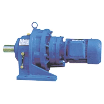
Advantages of Using a Cycloidal Gearbox
Cycloidal gearboxes offer several advantages that make them well-suited for various applications:
- High Torque Density: Cycloidal gearboxes provide a high torque output relative to their size and weight. This makes them ideal for applications where space is limited, and high torque is required.
- Compact Design: The unique arrangement of cycloidal pins and lobed profiles results in a compact gearbox design. This is advantageous when dealing with constrained installation spaces.
- Smooth and Precise Motion: Cycloidal motion generates smooth and controlled movement, making these gearboxes suitable for applications requiring accurate positioning, such as robotics and automation.
- High Shock Load Capacity: The multiple points of contact between the cycloidal pins and the lobes distribute the load, allowing cycloidal gearboxes to handle sudden shocks and overloads effectively.
- Backlash Elimination: Cycloidal gearboxes exhibit minimal backlash due to the nature of their motion. This is beneficial in applications where precise motion reversal is crucial.
- High Efficiency: The rolling contact between the pins and lobes contributes to efficient power transmission, resulting in relatively high efficiency levels.
- Reduced Wear and Noise: The rolling motion in cycloidal gearboxes leads to reduced wear on components, resulting in lower maintenance requirements and quieter operation.
- Versatility: Cycloidal gearboxes can handle a wide range of ratios and speeds, making them suitable for various industrial and automation applications.
Due to these advantages, cycloidal gearboxes are commonly used in robotics, automation, packaging machinery, conveyors, and other applications where compactness, high torque, and precise motion are critical.


editor by CX 2023-10-17
China Best Sales Speed Gear Reducer Bevel Helical Agricultural Cycloidal Drive Worm Gearbox gearbox definition
Product Description
ZheJiang CZPT Machinery Manufacturing Co.,LTD. is an innovative manufacturing enterprise specalizing in the production, design, sales and installation of bulk material conveying equipment.
The company mainly provides belt conveyor, tubular belt conveyor, mobile belt conveyor, screw conveyor, Bucket Elevator, chain conveyor, scraper conveyor and other material handling conveying equipment. It also provides conveyor idlers rollers,conveyor drum pulleys,conveyor belts, belt cleaners,impact beds,take-up frame and other components.
Juntong Conveyor has many years of experience in supplying to a diverse range of industries which includes coal, cement,steel iron, chemical,agricultural, power,mining, port, quarrying,mechanical & civil engineering, waste management & recycling.
We have a professional R&D team with plenty technical patents.and we can produce conveyor products in different standards such as CEMA, JIS, ISO, AS, GB and so on. Also,our products have already qualified IS09001, CE, SGS, BV, MA certifications,In addition, CZPT has established friendly and cooperative relationships with ZheJiang Material Handling Research Institute Co.,ltd( BMHRI), CZPT Research Institute (CCRI), HangZhou University of Science and Technology (TYUST) , etc., so that the company’s research and development level has always been at the forefront of innovation in the field of bulk material transportation.CZPT Conveyor has became a CZPT brand with great reputation for providing total conveyor confidence.
|
Shipping Cost:
Estimated freight per unit. |
To be negotiated |
|---|
| After-sales Service: | Warranty Service |
|---|---|
| Warranty: | 1 Year |
| Output Torque: | 800~100000n.M |
| Samples: |
US$ 0/Piece
1 Piece(Min.Order) | Order Sample |
|---|
| Customization: |
Available
| Customized Request |
|---|
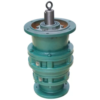
Distinguishing Features of Cycloidal Gearboxes
Cycloidal gearboxes, also known as cycloidal drives or cycloidal reducers, possess distinct characteristics that set them apart from other types of gearboxes:
- Principle of Operation: Cycloidal gearboxes utilize the principle of cycloidal motion, where input shaft movement is transformed into eccentric motion of the cycloidal disc. This unique mechanism results in smooth and consistent output motion.
- Compactness: Cycloidal gearboxes are renowned for their compact size and high torque density. The concentric design of the components contributes to their ability to transmit substantial torque in a relatively small package.
- Tooth Profile: Cycloidal gearboxes employ specialized cycloidal teeth, which involve both pinwheel and roller gears. This distinctive tooth profile contributes to the characteristic smooth and vibration-free operation.
- Reduction Mechanism: They often employ multi-lobed cam gears that interact with the pins on the cycloidal disc, resulting in multiple gear engagements per revolution and improved load distribution.
- Motion Control: Cycloidal gearboxes offer high positional accuracy and motion control due to the eccentric motion of the disc, making them suitable for robotics, automation, and precision applications.
- Backlash: They typically exhibit low backlash due to the nature of the engagement mechanism, making them advantageous for applications requiring precise and reversible motion.
- Applications: Cycloidal gearboxes are commonly used in various industries, including robotics, packaging, material handling, printing, and more, where their compactness, precision, and efficiency are valued.
These distinguishing features contribute to the unique capabilities and benefits of cycloidal gearboxes in specific applications.
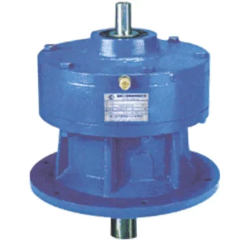
Maintenance Requirements for Cycloidal Gearboxes
Maintaining cycloidal gearboxes is essential to ensure their optimal performance and longevity. Here are some maintenance practices to consider:
- Lubrication: Regular lubrication is crucial to prevent wear and friction between moving parts. Use high-quality lubricants recommended by the gearbox manufacturer.
- Inspections: Regularly inspect the gearbox for signs of wear, damage, or oil leakage. Address any issues promptly to prevent further damage.
- Cleaning: Keep the gearbox clean and free from debris that could interfere with its operation. Cleanliness helps prevent contamination and wear.
- Torque Checks: Periodically check the tightness of fasteners and bolts to ensure they are properly secured. Loose fasteners can lead to misalignment and reduced performance.
- Seal Maintenance: Check and maintain seals to prevent oil leakage. Damaged seals should be replaced promptly to avoid lubricant loss.
- Temperature Monitoring: Monitor the operating temperature of the gearbox to ensure it remains within the recommended range. Excessive heat can lead to premature wear.
- Alignment: Ensure that the gearbox is properly aligned with other components to prevent misalignment-related issues.
- Regular Service: Follow the manufacturer’s recommended service intervals for more in-depth inspections and maintenance tasks.
Regular and proactive maintenance can extend the lifespan of cycloidal gearboxes, minimize downtime, and maintain their efficiency and performance over time.

Advantages of Using a Cycloidal Gearbox
Cycloidal gearboxes offer several advantages that make them well-suited for various applications:
- High Torque Density: Cycloidal gearboxes provide a high torque output relative to their size and weight. This makes them ideal for applications where space is limited, and high torque is required.
- Compact Design: The unique arrangement of cycloidal pins and lobed profiles results in a compact gearbox design. This is advantageous when dealing with constrained installation spaces.
- Smooth and Precise Motion: Cycloidal motion generates smooth and controlled movement, making these gearboxes suitable for applications requiring accurate positioning, such as robotics and automation.
- High Shock Load Capacity: The multiple points of contact between the cycloidal pins and the lobes distribute the load, allowing cycloidal gearboxes to handle sudden shocks and overloads effectively.
- Backlash Elimination: Cycloidal gearboxes exhibit minimal backlash due to the nature of their motion. This is beneficial in applications where precise motion reversal is crucial.
- High Efficiency: The rolling contact between the pins and lobes contributes to efficient power transmission, resulting in relatively high efficiency levels.
- Reduced Wear and Noise: The rolling motion in cycloidal gearboxes leads to reduced wear on components, resulting in lower maintenance requirements and quieter operation.
- Versatility: Cycloidal gearboxes can handle a wide range of ratios and speeds, making them suitable for various industrial and automation applications.
Due to these advantages, cycloidal gearboxes are commonly used in robotics, automation, packaging machinery, conveyors, and other applications where compactness, high torque, and precise motion are critical.


editor by CX 2023-09-11
China supplier New Type/Hot Sale K Series Reducer Bevel Helical Gearbox/Right Angle Gearbox for Plastic Extruder Cycloidal Electric Reducer cycloidal gearbox backlash
Product Description
HUAKE Hot Selling KA series gear box reducer geared motor reductor made in china
K series product performance
High transmission efficiency, low energy consumption and superior performance. High rigidity cast iron box with ribs; hard-toothed gears are made of high-quality alloy steel, the surface is carburized and quenched and hardened, and the teeth are finely machined, with stable transmission, low noise, large bearing capacity, low temperature rise and long service life.
Product Parameters
|
Brand Name |
HUAKE |
|
Product Name |
K Helical-bevel gear units |
|
Material |
Steel or cast iron |
|
Weight |
11Kg-1700Kg |
|
Color |
Customizable |
|
Heat treatment |
Carburising,Quenching,Gear Grinding |
|
Advantage |
1.K series spiral bevel gear reducer with small vibration, low noise, energy saving. 2.Selection of high quality steel material, steel cast iron box, gear surface after high frequency heat treatment. |
Product Description
Our process of production
Our product line
| Hardness: | Hardened Tooth Surface |
|---|---|
| Installation: | 90 Degree |
| Layout: | Expansion |
| Gear Shape: | Bevel Gear |
| Step: | Single-Step |
| Type: | Gear Reducer |
| Samples: |
US$ 1000/Piece
1 Piece(Min.Order) | |
|---|
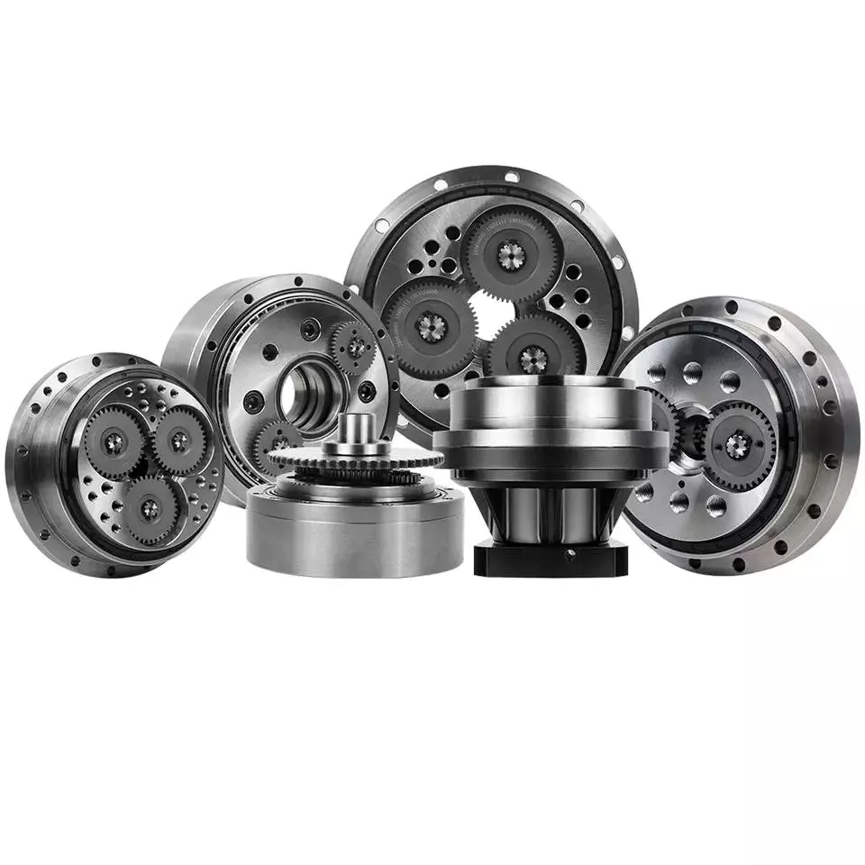
How to Calculate Transmission Ratio for a Cycloidal Gearbox
Using a cycloidal gearbox can be very useful in a wide variety of situations. However, it’s important to understand how to use it properly before implementing it. This article discusses the benefits of using a cycloidal gearbox, how to calculate the transmission ratio, and how to determine the effects of dynamic and inertial forces on the gearbox.
Dynamic and inertial effects
Various studies have been done to study the dynamic and inertial effects of cycloidal gearboxes. These studies have been performed using numerical, analytical and experimental methods. Depending on the nature of the load and its distribution along the gear, a variety of models have been developed. These models use finite element method to determine accurate contact stresses. Some of these models have been developed to address the nonlinear elasticity of contacts.
Inertial imbalance in a cycloidal gearbox causes vibration and can affect the efficiency of the device. This can increase mechanical losses and increase wear and tear. The efficiency of the device also depends on the torque applied to the cycloidal disk. The effectiveness of the device increases as the load increases. Similarly, the nonlinear contact dynamics are also associated with an increase in efficiency.
A new model of a cycloidal reducer has been developed to predict the effects of several operational conditions. The model is based on rigid body dynamics and uses a non-linear stiffness coefficient. The model has been validated through numerical and analytical methods. The model offers drastic reduction in computational costs. The model allows for a quick analysis of several operational conditions.
The main contribution of the paper is the investigation of the load distribution on the cycloidal disc. The study of this aspect is important because it allows for an analysis of the rotating parts and stresses. It also provides an indication of which gear profiles are best suited for optimizing torque transmission. The study has been conducted with a variety of cycloidal gearboxes and is useful in determining the performance of different types of cycloidal gearboxes.
To study the load distribution on the cycloidal disc, the authors investigated the relationship between contact force, cycloidal gearboxes and different gear profiles. They found that the non-linear contact dynamics have a large impact on the efficiency of a cycloidal gearbox. The cycloidal gearbox is an ideal solution for applications that involve highly dynamic servos. It can also be used in machine tool applications and food processing industries.
The study found that there are three common design principles of cycloidal reducers. These are the contact force distribution, the speed reduction and the trochoidal profile of the cycloidal disc. The trochoidal profile has to be defined carefully to ensure correct mating of the rotating parts. The trochoidal profile provides an indication of which gear profiles are best for optimizing torque transmission. The contact force distribution can be improved by refining the mesh along the disc’s width.
As the input speed increases, the efficiency of the reducer increases. This is because contact forces are constantly changing in magnitude and orientation. A cycloidal reducer with a one tooth difference can reduce input speed by up to 87:1 in a single stage. It also has the ability to handle high-cycle moves without backlash.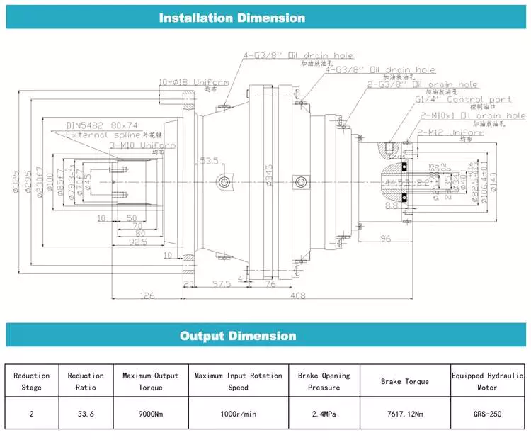
Transmission ratio calculation
Getting the correct transmission ratio calculation for a cycloidal gearbox requires a good understanding of what a gearbox is, as well as the product that it is being used for. The correct ratio is calculated by dividing the output speed of the output gear by the input speed of the input gear. This is usually accomplished by using a stopwatch. In some cases, a catalog or product specification may be required. The correct ratio is determined by a combination of factors, such as the amount of torque applied to the mechanism, as well as the size of the gears involved.
A cycloidal gear is a type of gear tooth profile that can be represented using a spline. It is also possible to model a gear with a cycloidal profile by using a spline to connect points against the beginning of a coordinate system. This is important in the design and functionality of a gear.
There are many different gears used in machines and devices. These include the herringbone gear, the helical gear and the spiral bevel gear. The best transmission ratios are typically obtained with a cycloidal gearbox. In addition to ensuring the accuracy of positioning, a cycloidal gearbox provides excellent backlash. Cycloid gears have a high degree of mechanical efficiency, low friction, and minimal moment of inertia.
A cycloidal gearbox is often referred to as a planetary gearbox, though it is technically a single-stage gearbox. In addition to having a ring gear, the gearbox has an eccentric bearing that drives the cycloidal disc in an eccentric rotation. This makes the cycloidal gearbox a good choice for high gear ratios in compact designs.
The cycloid disc is the key element of a cycloidal gearbox. The cycloid disc has n=9 lobes, and each lobe of the disc moves by a lobe for every revolution of the drive shaft. The cycloid disc is then geared to a stationary ring gear. The cycloidal disc’s lobes act like teeth on the stationary ring gear.
There are many different gears that are classified by the profile of the gear teeth. The most common gears are the involute and helical gears. Most motion control gears include spur designs. However, there are many other types of gears that are used in various applications. The cycloidal gear is one of the more complicated gears to design. The cycloid disc’s outline can be represented using markers or smooth lines, though a scatter chart will also do.
The cycloid disc’s lobes rotate on a reference pitch circle of pins. These pins rotate 40 deg during the eccentric rotation of the drive shaft. The pins rotate around the disc to achieve a steady rotation of the output shaft.
The cycloid disc’s other obvious, and possibly more important, feature is the’magic’ number of pins. This is the number of pins that protrude through the face of the disc. The disc has holes that are larger than the pins. This allows the pins to protrude through the disc and attach to the output shaft.
Application
Whether you’re building a robot drive or you’re simply looking for a gearbox to reduce the speed of your vehicle, a cycloidal gearbox is a great way to achieve a high reduction ratio. Cycloidal gearboxes are a low-friction, lightweight design that has an extremely stable transmission. They are suitable for industrial robots and can be used in many applications, including positioning robots.
Cycloidal gearboxes reduce speed by using eccentric motion. The eccentric motion enables the entire internal gear to rotate in wobbly cycloidal motion, which is then translated back into circular rotation. This eliminates the need for stacking gear stages. Cycloidal gearboxes also have less friction, higher strength, and greater durability than conventional gearboxes.
The cycloidal gearbox is also used in a number of applications, including marine propulsion systems, and robot drives. Cycloidal gearboxes reduce vibration by using offset gearing to cancel out vibrations.
Cycloidal gears have lower friction, higher strength, and better torsional stiffness than involute gears. They also have a reduced Hertzian contact stress, making them better than involute gears for use with shock loads. They also have a smaller size and weight than conventional gearboxes, and they have a higher reduction ratio than involute gears.
Cycloidal gears are typically used to reduce the speed of motors, but they also offer a number of other advantages. Cycloidal gearboxes have a smaller footprint than other gearboxes, allowing them to fit into confined spaces. They also have low backlash, allowing for precise movement. Cycloidal gears have a higher efficiency, resulting in lower power requirements and lower wear.
The cycloidal disc is one of the most important components of the gearbox. Cycloidal discs are normally designed with a short cycloid, which minimizes the eccentricity of the disc. They are also designed with a shortened flank, resulting in better strength and less stress concentration. Cycloidal discs are typically geared to a stationary ring gear. The cycloid is designed to roll around the stationary ring pins, which push against the circular holes in the disc. Cycloidal gearboxes typically employ two degrees of shift.
Cycloidal drives are ideal for heavy load applications. They also have high torsional stiffness, which makes them highly resistant to shock loads. Cycloidal drives also offer a high reduction ratio, which can be achieved without the need for a large input shaft. They are also compact and have a high service life.
The output shaft of a cycloidal gearbox always has two degrees of shifting, which ensures that the input and output shafts always rotate at a different speed. The output shaft would be a pin casing around the drive disks, which would also allow for easy maintenance.
Cycloidal gearboxes are also very compact and lightweight, so they are ideal for use in industrial robots. The cycloidal gearbox reducer is the most stable, low-vibration reducer in industrial robots, and it has a wide transmission ratio range.

editor by CX 2023-06-08
China factory New Type/Hot Sale K Series Reducer Bevel Helical Gearbox/Right Angle Gearbox for Plastic Extruder Cycloidal Electric Reducer small cycloidal gearbox
Product Description
HUAKE Hot Selling KA series gear box reducer geared motor reductor made in china
K series product performance
High transmission efficiency, low energy consumption and superior performance. High rigidity cast iron box with ribs; hard-toothed gears are made of high-quality alloy steel, the surface is carburized and quenched and hardened, and the teeth are finely machined, with stable transmission, low noise, large bearing capacity, low temperature rise and long service life.
Product Parameters
|
Brand Name |
HUAKE |
|
Product Name |
K Helical-bevel gear units |
|
Material |
Steel or cast iron |
|
Weight |
11Kg-1700Kg |
|
Color |
Customizable |
|
Heat treatment |
Carburising,Quenching,Gear Grinding |
|
Advantage |
1.K series spiral bevel gear reducer with small vibration, low noise, energy saving. 2.Selection of high quality steel material, steel cast iron box, gear surface after high frequency heat treatment. |
Product Description
Our process of production
Our product line
| Hardness: | Hardened Tooth Surface |
|---|---|
| Installation: | 90 Degree |
| Layout: | Expansion |
| Gear Shape: | Bevel Gear |
| Step: | Single-Step |
| Type: | Gear Reducer |
| Samples: |
US$ 1000/Piece
1 Piece(Min.Order) | |
|---|

The Advantages of Using a Cyclone Gearbox
Using a cycloidal gearbox to drive an input shaft is a very effective way to reduce the speed of a machine. It does this by reducing the speed of the input shaft by a predetermined ratio. It is capable of very high ratios in relatively small sizes.
Transmission ratio
Whether you’re building a marine propulsion system or a pump for the oil and gas industry, there are certain advantages to using cycloidal gearboxes. Compared to other gearbox types, they’re shorter and have better torque density. These gearboxes also offer the best weight and positioning accuracy.
The basic design of a cycloidal gearbox is similar to that of a planetary gearbox. The main difference is in the profile of the gear teeth.
Cycloid gears have less tooth flank wear and lower Hertzian contact stress. They also have lower friction and torsional stiffness. These advantages make them ideal for applications that involve heavy loads or high-speed drives. They’re also good for high gear ratios.
In a cycloidal gearbox, the input shaft drives an eccentric bearing, while the output shaft drives the cycloidal disc. The cycloidal disc rotates around a fixed ring, and the pins of the ring gear engage the holes in the disc. The pins then drive the output shaft as the disc rotates.
Cycloid gears are ideal for applications that require high gear ratios and low friction. They’re also good for applications that require high torsional stiffness and shock load resistance. They’re also suitable for applications that require a compact design and low backlash.
The transmission ratio of a cycloidal gearbox is determined by the number of lobes on the cycloidal disc. The n=n design of the cycloidal disc moves one lobe per revolution of the input shaft.
Cycloid gears can be manufactured to reduce the gear ratio from 30:1 to 300:1. These gears are suitable for high-end applications, especially in the automation industry. They also offer the best positioning accuracy and backlash. However, they require special manufacturing processes and require non-standard characteristics.
Compressive force
Compared with conventional gearboxes, the cycloidal gearbox has a unique set of kinematics. It has an eccentric bearing in a rotating frame, which drives the cycloidal disc. It is characterized by low backlash and torsional stiffness, which enables geared motion.
In this study, the effects of design parameters were investigated to develop the optimal design of a cycloidal reducer. Three main rolling nodes were studied: a cycloidal disc, an outer race and the input shaft. These were used to analyze the motion related dynamic forces, which can be used to calculate stresses and strains. The gear mesh frequency was calculated using a formula, which incorporated a correction factor for the rotating frame of the outer race.
A three-dimensional finite element analysis (FEA) study was conducted to evaluate the cycloidal disc. The effects of the size of the holes on the disc’s induced stresses were investigated. The study also looked at the torque ripple of a cycloidal drive.
The authors of this study also explored backlash distribution in the output mechanism, which took into account the machining deviations and structure and geometry of the output mechanism. The study also looked at the relative efficiency of a cycloidal reducer, which was based on a single disc cycloidal reducer with a one-tooth difference.
The authors of this study were able to deduce the contact stress of the cycloidal disc, which is calculated using the material-based contact stiffness. This can be used to determine accurate contact stresses in a cycloidal gearbox.
It is important to know the ratios needed for calculation of the bearing rate. This can be calculated using the formula f = k (S x R) where S is the volume of the element, R is the mass, k is the contact stiffness and f is the force vector.
Rotational direction
Unlike the conventional ring gear which has a single axis of rotation, cycloidal gearbox has three rotational axes which are parallel and are located in a single plane. A cycloidal gearbox has excellent torsional stiffness and shock load capacity. It also ensures constant angular velocity, and is used in high-speed gearbox applications.
A cycloidal gearbox consists of an input shaft, a drive member and a cycloidal disc. The disc rotates in one direction, while the input shaft rotates in the opposite direction. The input shaft eccentrically mounts to the drive member. The cycloidal disc meshes with the ring-gear housing, and the rotational motion of the cycloidal disc is transferred to the output shaft.
To calculate the rotational direction of a cycloidal gearbox, the cycloid must have the correct angular orientation and the centerline of the cycloid should be aligned with the center of the output hole. The cycloid’s shortest length should be equal to the radius of the pin circle. The cycloid’s largest radius should be the size of the bearing’s exterior diameter.
A single-stage gear will not have much space to work with, so you’ll need a multistage gear to maximize space. This is also the reason that cycloid gears are usually designed with a shortened cycloid.
To calculate the most efficient tooth profile for a cycloidal gear, a new method was devised. This method uses a mathematical model that uses the cycloid’s rotational direction and a few other geometric parameters. Using a piecewise function related to the distribution of pressure angle, the cycloid’s most efficient profile is determined. It is then superimposed on the theoretical profile. The new method is much more flexible than the conventional method, and can adapt to changing trends of the cycloidal profile.
Design
Several designs of cycloidal gearboxes have been developed. These gearboxes have a large reduction ratio in one stage. They are mainly used for heavy machines. They provide good torsional stiffness and shock load capacity. However, they also have vibrations at high RPM. Several studies have been conducted to find a solution to this problem.
A cycloidal gearbox is designed by calculating the reduction ratio of a mechanism. This ratio is obtained by the size of the input speed. This is then multiplied by the reduction ratio of the gear profile.
The most important factor in the design of a cycloidal gearbox is the load distribution along the width of the gear. Using this as a design criterion, the amplitude of vibration can be reduced. This will ensure that the gearbox is working properly. In order to generate proper mating conditions, the trochoidal profile on the cycloidal disc periphery must be defined accurately.
One of the most common forms of cycloidal gears is circular arc toothing. This is the most common type of toothing used today.
Another form of gear is the hypocycloid. This form requires the rolling circle diameter to be equal to half the base circle diameter. Another special case is the point tooth form. This form is also called clock toothing.
In order to make this gear profile work, the initial point of contact must remain fixed to the edge of the rolling disk. This will generate the hypocycloid curve. The curve is traced from this initial point.
To investigate this gear profile, the authors used a 3D finite element analysis. They used the mathematical model of gear manufacturing that included kinematics parameters, output moment calculations, and machining steps. The resulting design eliminated backlash.
Sizing and selection
Choosing a gearbox can be a complex task. There are many factors that need to be taken into account. You need to determine the type of application, the required speed, the load, and the ratio of the gearbox. By gaining this information, you can find a solution that works best for you.
The first thing you need to do is find the proper size. There are several sizing programs available to help you determine the best gearbox for your application. You can start by drawing a cycloidal gear to help you create the part.
During sizing, it is important to consider the environment. Shock loads, environmental conditions, and ambient temperatures can increase wear on the gear teeth. The temperature also has a significant impact on lubrication viscosities and seal materials.
You also need to consider the input and output speed. This is because the input speed will change your gearbox ratio calculations. If you exceed the input speed, you can damage the seals and cause premature wear on the shaft bearings.
Another important aspect of sizing is the service factor. This factor determines the amount of torque the gearbox can handle. The service factor can be as low as 1.4, which is sufficient for most industrial applications. However, high shock loads and impact loads will require higher service factors. Failure to account for these factors can lead to broken shafts and damaged bearings.
The output style is also important. You need to determine if you want a keyless or keyed hollow bore, as well as if you need an output flange. If you choose a keyless hollow bore, you will need to select a seal material that can withstand the higher temperatures.

editor by CX 2023-06-07
China Custom Helical Bevel Gearbox Helical Couping Helical Gear Box cycloidal gear reducer design
Product Description
Features
1.Wide transmission rate, strong output torque
2.Compact mechanical structure, light weight, small volume&Good heat-dissipating
3.Smooth operation with lower noise or vibration
4.Easy mounting, free linking, high efficiency
5.Upto 96% transmission efficiency
5. PERFECT SUBSTITUDE FOR SEW AND TRANSTECNO PRODUCTS
Applications
Wide range of application,including light industry of food &beverage, Cement,
package,construction material,chemicals and etc.
Technical data:
| Model | SRC01, SRC02, SRC03, SRC04 |
| Single unit versions | SRC-P IEC motor mounting SRC-HS shaft mounting |
| Power | 0.25—-4KW |
| reduction ratio | 3.66 – 54 |
| Output torque | 3.0—500N.M |
| Gear material | 20CrMnTi with carburizing and quenching.The hardness of surface is 56-62HRC with carbonized layer 0.5-0.8mm |
After-sale service:
One year warranty,subject to proper operation and installation;free technical support all the time.
|
Shipping Cost:
Estimated freight per unit. |
To be negotiated|
|
|---|
| Application: | Motor |
|---|---|
| Layout: | Cycloidal |
| Hardness: | Hardened Tooth Surface |
| Customization: |
Available
| Customized Request |
|---|
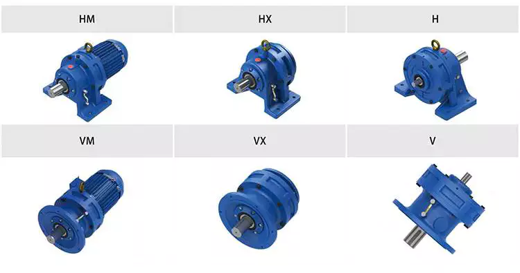
Condition Monitoring of Cyclone Gearboxes
Whether you’re considering using a cycloidal gearbox in your home, office, or garage, you’ll want to make sure it’s made of quality material. You also want to make sure it’s designed properly, so it won’t be damaged by vibrations.
Planetary gearboxes
Compared to cycloidal gearboxes, planetary gearboxes are lighter and more compact, but they lack the precision and durability of the former. They are better suited for applications with high torque or speed requirements. For this reason, they are usually used in robotics applications. But, cycloidal gearboxes are still better for some applications, including those involving shock loads.
There are many factors that affect the performance of gearboxes during production. One of these is the number of teeth. In the case of planetary gearboxes, the number of teeth increases with the number of planets. The number of teeth is reduced in cycloidal gearboxes, which results in higher transmission ratios. These gearboxes also have lower breakaway torques, which means that they can be controlled more easily by the user.
A cycloid gearbox is comprised of three main parts: the ring gear, the sun gear, and the input shaft. The ring gear is fixed in the gearbox, while the sun gear transmits the rotation to the planet gears. The input shaft transfers motion to the sun gear, which in turn transmits it to the output shaft. The output shaft has a larger torque than the input shaft.
Cycloid gears have better torsional stiffness, lower wear, and lower Hertzian contact stress. However, they are also larger in size and require highly accurate manufacturing. Cycloid gears can be more difficult to manufacture than involute gears, which require large amounts of precision.
Cycloid gears can offer transmission ratios up to 300:1, and they can do this in a small package. They also have lower wear and friction, which makes them ideal for applications that require a high transmission ratio.
Cycloid gearboxes are usually equipped with a backlash of about one angular minute. This backlash provides the precision and control necessary for accurate movement. They also provide low wear and shock load capacity.
Planetary gearboxes are available in single and two-stage designs, which increase in length as stages are added. In addition to the two stages, they can be equipped with an optional output bearing, which takes up mounting space. In some applications, a third stage is also available.
Involute gears
Generally, involute gears are more complex to manufacture than cycloidal gears. For example, an involute gear tooth profile has a single curve while a cycloidal gear tooth profile has two curves. In addition, the involute curve is not within the base circle.
The involute curve is a very important component of a gear tooth and it can significantly influence the quality of contact meshing between teeth. Various works have been done on the subject, mainly focusing on the operating principles. In addition, the most important characteristic of the double-enveloping cycloid drive is its double contact lines between the meshing tooth pairs.
Cycloid gears are more powerful, less noisy, and last longer than involute gears. They also require less manufacturing operations during production. However, cycloid gears are more expensive than involute gears. Involute gears are more commonly used in linear motions while cycloid gears are used for rotary motions.
Although cycloid gears are more technically advanced, involute gears have the superior quality and are more aesthetically pleasing. Cycloid gears are used in various industrial applications such as pumps and compressors. They are also widely used in the watch industry. Nevertheless, involute gears have not yet replaced cycloid gears in the watch industry.
The cycloid disc has a number of pins around its outer edge, while an involute gear has only a single curve for the teeth. In addition, cycloid gears have a more robust and reliable design. Involute gears, on the other hand, have a cheaper rack cutter and less expensive involute teeth.
The cycloid disc’s transmission accuracy is about 98.5%, while the ring gear’s transmission accuracy is about 96%. The cycloid disc’s rotational velocity has a magnitude of 3 rad/s. A small change in the center distance does not affect the transmission accuracy. However, rotational velocity fluctuation can affect the transmission accuracy.
Cycloid gears also have the cycloid gear disc’s rotational velocity. The disc has N lobes. However, the cycloid gear disc’s transmission accuracy is still not perfect. This is because of the large rotational angles between the lobes. This also makes it difficult to manufacture.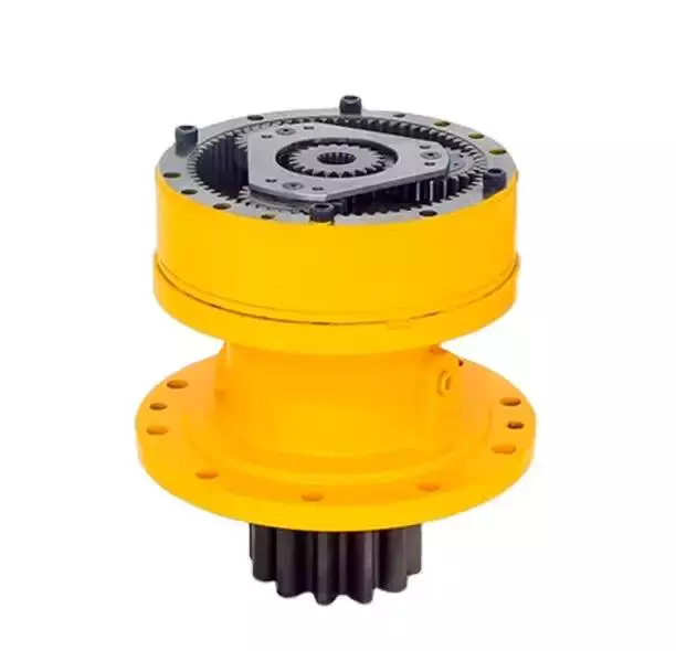
Vibrations
Using modern techniques for vibration diagnostics and data-driven methods, this article presents a new approach to condition monitoring of cycloidal gearboxes. This approach focuses on detecting the root cause of gearbox failure. The article aims to provide a unified approach to gear designers.
A cycloidal gearbox is a high-precision gearbox that is used in heavy-duty machines. It has a large reduction ratio, which makes it necessary to have a very large input speed. Cycloid gears have high accuracy, but they are susceptible to vibration issues. In this article, the authors describe how a cycloidal gearbox works and how vibrations are measured. They also show how this gearbox can be used to detect faults.
The gearbox is used in positioners, multi-axis robots, and heavy-duty machines. The main characteristics of this gearbox are the high accuracy, the overload capacity, and the large reduction ratio.
There is little documentation on vibrations and condition monitoring of cycloidal gearboxes. The authors describe their approach to the problem, using a cycloidal gearbox and a testing bench. Their approach involves measuring the frequency of the gearbox with different input speeds.
The results show a good separation between the healthy and damaged states. Fault frequencies show up in the lower orders of frequencies. Faults can be detected using binning, which eliminates the need for a tachometer. In addition, binning is combined with Principal Component Analysis to determine the state of the gearbox.
This method is compared to traditional techniques. In addition, the results show how binning can be used to calculate the defect frequencies of the bearings. It is also used to determine the frequencies of the components.
The signals from the test bench are acquired using four sensors. These sensors are medium sensitivity 100 mV/g accelerometers. The signals are then processed using different signal processing techniques. The results show that the vibration signals are correlated with the internal motion of the gearbox. This information is used to identify the internal frequency of the transmission.
The frequency analysis of vibration signals is performed in cyclostationary and noncyclostationary conditions. The signals are then analyzed to determine the magnitude of the gear meshing frequency.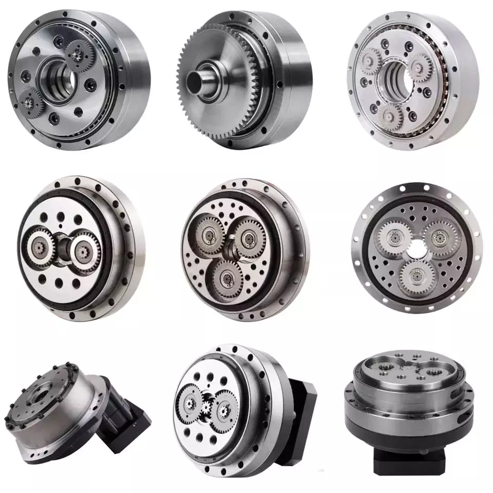
Design
Using precision gearboxes, servomotors can now control heavy loads at high speed. Unlike cam indexing devices, cycloidal gears provide extremely accurate positioning and high torque. They also provide excellent torsional stiffness and shock load capacity.
Cycloid gears are specially designed to minimize vibration at high RPM. Unlike involute gears, they are not stacked, which reduces friction and forces experienced by each tooth. In addition, cycloidal gears have lower Hertzian contact stress.
Cycloid gears are often used in multi-axis robots for positioners. They can provide transmission ratios as high as 300:1 in a compact package. They are also used in first joints in heavy machines. However, they require extremely accurate manufacturing. They are also more difficult to produce than involute gears.
A cycloidal gearbox is a type of planetary gearbox. Cycloid gears are specially designed for high gear ratios. They also have the ability to provide a large reduction ratio in a single stage. They are increasingly used in first joints in heavy machines. They are also becoming more common in robotics.
In order to achieve a large reduction ratio, the input speed of the gear must be very high. Generally, the input speed is between 500 rpm and 4500 rpm. However, in some cases, the input speed may be lower.
A cycloid is formed by rolling a rolling circle on a base circle. The ratio between the rolling circle diameter and the base circle diameter determines the shape of the cycloid. A hypocycloid is formed by rolling primarily on the inside of the base circle, while an epicycloid is formed by rolling primarily on the outside of the base circle.
Cycloid gears have a very small backlash, which minimizes the forces experienced by each tooth. These gears also have a good torsional stiffness, low friction, and shock load capacity. They also provide the best positioning accuracy.
The cycloidal gearbox was designed and built at Radom University. The design was based on three different cycloidal gears. The first pair had the external profile at the nominal dimension, while the second pair had the profile minus tolerance. The load plate had threaded screw holes arranged 15 mm away from the center.

editor by CX 2023-05-12
China SWL screw jack for lift system power transmission 180 ratio reduction gearbox shaft mount reducer bevel helical gear unit with Best Sales
Guarantee: 3 years
Applicable Industries: Creating Substance Retailers, Equipment Fix Retailers, Foods & Beverage Factory, Farms, Cafe, Property Use, Design works, 1 way clutch deep groove ball bearing CSK6304 CSK6305 CSK6306 P PP CSK6304P CSK6305P CSK6306P CSK6304PP CSK6305PP CSK6306PP Strength & Mining
Bodyweight (KG): 30 KG
Personalized help: OEM, ODM, OBM
Gearing Arrangement: Worm
Enter Pace: three hundred
Output Speed: 300
Certification: ISO9001-2008, CE
Lifting Potential: As request
Equipment material: Lower carbon higher alloy metal
Heat therapy: Carburising, quenching, gear grinding
Packaging Details: Standard exporting package deal
Port: HangZhou Port, ZheJiang Port
SWL sequence Screw jack for carry program tables has the features of compacted construction, OEM 55GP micro steel equipment motor twelve v 12v 24v large torque 25nm 50nm 40nm 100kg 60 minimal 300 rpm 120w brush dc planetary gearmotor light and moveable, versatile, trustworthy, lengthy provider life, straightforward to installation, and self-locking whilst cease.
Certifications
Trade Exhibits
Packaging & ShippingPacking Information : Normal carton/Pallet/Regular picket scenario
Shipping and delivery Information : 15-30 working times upon payment
Company Details
other series product
| Precision Planetary gearbox | Robotic RV gearbox speed reducer |
| Personalized manufactured Non-regular Gearbox | UDL Collection Variator |
| PYZ Sequence Helical Tooth Shaft Mounted Reducer | 8000 Collection Cycloidal Reducer |
| SLT Series Spiral Bevel Gearbox | SLSWL Collection Worm Screw Jack |
| SLP Series Planetary Reducer | SLH/SLB Series Substantial Power Reducer |
| NMRV Sequence Worm Reducer | BKM Sequence Helical-hypoid Reducer |
| SLRC Series Helical Reducer | SLSMR Collection Shaft Mounted Reducer |
| SLXG Sequence Shaft Mounted Reducer | X/B Sequence Cycloidal Reducer |
| SLR/SLF/SLK/SLS Sequence Helical Reducer |
Speak to
What Is a Gearbox?
There are several factors to consider when choosing a gearbox. Backlash, for example, is a consideration, as it is the angle at which the output shaft can rotate without the input shaft moving. While this isn’t necessary in applications without load reversals, it is important for precision applications involving load reversals. Examples of these applications include automation and robotics. If backlash is a concern, you may want to look at other factors, such as the number of teeth in each gear.
Function of a gearbox
A gearbox is a mechanical unit that consists of a chain or set of gears. The gears are mounted on a shaft and are supported by rolling element bearings. These devices alter the speed or torque of the machine they are used in. Gearboxes can be used for a wide variety of applications. Here are some examples of how gearboxes function. Read on to discover more about the gears that make up a gearbox.
Regardless of the type of transmission, most gearboxes are equipped with a secondary gear and a primary one. While the gear ratios are the same for both the primary and secondary transmission, the gearboxes may differ in size and efficiency. High-performance racing cars typically employ a gearbox with two green and one blue gear. Gearboxes are often mounted in the front or rear of the engine.
The primary function of a gearbox is to transfer torque from one shaft to another. The ratio of the driving gear’s teeth to the receiving member determines how much torque is transmitted. A large gear ratio will cause the main shaft to revolve at a slower speed and have a high torque compared to its counter shaft. Conversely, a low gear ratio will allow the vehicle to turn at a lower speed and produce a lower torque.
A conventional gearbox has input and output gears. The countershaft is connected to a universal shaft. The input and output gears are arranged to match the speed and torque of each other. The gear ratio determines how fast a car can go and how much torque it can generate. Most conventional transmissions use four gear ratios, with one reverse gear. Some have two shafts and three inputs. However, if the gear ratios are high, the engine will experience a loss of torque.
In the study of gearbox performance, a large amount of data has been collected. A highly ambitious segmentation process has yielded nearly 20,000 feature vectors. These results are the most detailed and comprehensive of all the available data. This research has a dual curse – the first is the large volume of data collected for the purpose of characterization, while the second is the high dimensionality. The latter is a complication that arises when the experimental gearbox is not designed to perform well.
Bzvacklash
The main function of a gearhead is to multiply a moment of force and create a mechanical advantage. However, backlash can cause a variety of issues for the system, including impaired positioning accuracy and lowered overall performance. A zero backlash gearbox can eliminate motion losses caused by backlash and improve overall system performance. Here are some common problems associated with backlash in gearheads and how to fix them. After you understand how to fix gearbox backlash, you’ll be able to design a machine that meets your requirements.
To reduce gearbox backlash, many designers try to decrease the center distance of the gears. This eliminates space for lubrication and promotes excessive tooth mesh, which leads to premature mesh failure. To minimize gearbox backlash, a gear manufacturer may separate the two parts of the gear and adjust the mesh center distance between them. To do this, rotate one gear with respect to the fixed gear, while adjusting the other gear’s effective tooth thickness.
Several manufacturing processes may introduce errors, and reducing tooth thickness will minimize this error. Gears with bevel teeth are a prime example of this. This type of gear features a small number of teeth in comparison to its mating gear. In addition to reducing tooth thickness, bevel gears also reduce backlash. While bevel gears have fewer teeth than their mating gear, all of their backlash allowance is applied to the larger gear.
A gear’s backlash can affect the efficiency of a gearbox. In an ideal gear, the backlash is zero. But if there is too much, backlash can cause damage to the gears and cause it to malfunction. Therefore, the goal of gearbox backlash is to minimize this problem. However, this may require the use of a micrometer. To determine how much gearbox backlash you need, you can use a dial gauge or feeler gauge.
If you’ve been looking for a way to reduce backlash, a gearbox’s backlash may be the answer. However, backlash is not a revolt against the manufacturer. It is an error in motion that occurs naturally in gear systems that change direction. If it is left unaccounted for, it can lead to major gear degradation and even compromise the entire system. In this article, we’ll explain how backlash affects gears and how it affects the performance of a gearbox.
Design
The design of gearboxes consists of a variety of factors, including the type of material used, power requirements, speed and reduction ratio, and the application for which the unit is intended. The process of designing a gearbox usually begins with a description of the machine or gearbox and its intended use. Other key parameters to consider during gearbox design include the size and weight of the gear, its overall gear ratio and number of reductions, as well as the lubrication methods used.
During the design process, the customer and supplier will participate in various design reviews. These include concept or initial design review, manufacturing design validation, critical design review, and final design review. The customer may also initiate the process by initiating a DFMEA. After receiving the initial design approval, the design will go through several iterations before the finalized design is frozen. In some cases, the customer will require a DFMEA of the gearbox.
The speed increaser gearboxes also require special design considerations. These gearboxes typically operate at high speeds, causing problems with gear dynamics. Furthermore, the high speeds of the unit increase frictional and drag forces. A proper design of this component should minimize the effect of these forces. To solve these problems, a gearbox should incorporate a brake system. In some cases, an external force may also increase frictional forces.
Various types of gear arrangements are used in gearboxes. The design of the teeth of the gears plays a significant role in defining the type of gear arrangement in the gearbox. Spur gear is an example of a gear arrangement, which has teeth that run parallel to the axis of rotation. These gears offer high gear ratios and are often used in multiple stages. So, it is possible to create a gearbox that meets the needs of your application.
The design of gearboxes is the most complex process in the engineering process. These complex devices are made of multiple types of gears and are mounted on shafts. They are supported by rolling element bearings and are used for a variety of applications. In general, a gearbox is used to reduce speed and torque and change direction. Gearboxes are commonly used in motor vehicles, but can also be found in pedal bicycles and fixed machines.
Manufacturers
There are several major segments in the gearbox market, including industrial, mining, and automotive. Gearbox manufacturers are required to understand the application and user industries to design a gearbox that meets their specific requirements. Basic knowledge of metallurgy is necessary. Multinational companies also provide gearbox solutions for the power generation industry, shipping industry, and automotive industries. To make their products more competitive, they need to focus on product innovation, geographical expansion, and customer retention.
The CZPT Group started as a small company in 1976. Since then, it has become a global reference in mechanical transmissions. Its production range includes gears, reduction gearboxes, and geared motors. The company was the first in Italy to achieve ISO certification, and it continues to grow into one of the world’s leading manufacturers of production gearboxes. As the industry evolves, CZPT focuses on research and development to create better products.
The agriculture industry uses gearboxes to implement a variety of processes. They are used in tractors, pumps, and agricultural machinery. The automotive industry uses gears in automobiles, but they are also found in mining and tea processing machinery. Industrial gearboxes also play an important role in feed and speed drives. The gearbox industry has a diverse portfolio of manufacturers and suppliers. Here are some examples of gearboxes:
Gearboxes are complex pieces of equipment. They must be used properly to optimize efficiency and extend their lifespan. Manufacturers employ advanced technology and strict quality control processes to ensure their products meet the highest standards. In addition to manufacturing precision and reliability, gearbox manufacturers ensure that their products are safe for use in the production of industrial machinery. They are also used in office machines and medical equipment. However, the automotive gearbox market is becoming increasingly competitive.


editor by czh 2023-02-17