Product Description
Product Description
RC Series Coaxial Helical Gear Box Flange Mounted Gear Reducer
Components:
1. Housing:Aluminum Alloys
2. Gears:Hardened Helical Gears
3. Input Configurations:Hollow Shaft with IEC Normalized Motor Flange /Solid Shaft Input
4. Applicable Motors:IEC-normalized Motors and Brake Motors/Explosion-proof Motors/Inverter Motors/Servo Motors
5. Output Configurations:Solid Shaft with B5 Output Flange/Solid Shaft with B14 Output Flange
Models:
RC(Foot-mounted): RC01,RC02,RC03,RC04
RCF(B5 Flange-mounted): RCF01,RCF02,RCF03,RCF04
RCZ(B14 Flange-mounted): RCZ01,RCZ02,RCZ03,RCZ04
Features:
1. Modular design, dismountable frame foot, optional different frame sizes and flanges
2. Aluminum housing, compact structures, light weight
3. Carburizing and grinding hardened gears, sturdy and durable
4. Multiple mounting positions
5. Low noise
Detailed Photos
Product Parameters
Applications:Textile, Food, Ceramics, Packaging, Logistics, Plastics Industry
Installation:Foot-mounted/B5 Flange-mounted/B14 Flange-mounted
Lubrication:Oil-bath and Splash Lubrication/Cooling:/Natural Cooling
| Frame Sizes | Power | Ratio | Max. Torque |
| 01,02,03,04 | 0.12kW~4kW | 3.66~54 | 120N.m~500N.m |
Packaging & Shipping
Company Profile
Our Advantages
Our Services:
| Pre-sale services | 1. Select equipment model. |
| 2.Design and manufacture products according to clients’ special requirement. | |
| 3.Train technical personal for clients | |
| Services during selling | 1.Pre-check and accept products ahead of delivery. |
| 2. Help clients to draft solving plans. | |
| After-sale services | 1.Assist clients to prepare for the first construction scheme. |
| 2. Train the first-line operators. | |
| 3.Take initiative to eliminate the trouble rapidly. | |
| 4. Provide technical exchanging. |
FAQ
1.Q:What kinds of gearbox can you produce for us?
A:Main products of our company: UDL series speed variator,RV series worm gear reducer, ATA series shaft mounted gearbox, X,B series gear reducer,
P series planetary gearbox and R, S, K, and F series helical-tooth reducer, more
than 1 hundred models and thousands of specifications
2.Q:Can you make as per custom drawing?
A: Yes, we offer customized service for customers.
3.Q:What is your terms of payment ?
A: 30% Advance payment by T/T after signing the contract.70% before delivery
4.Q:What is your MOQ?
A: 1 Set
If you have any demand for our products please feel free to contact me.
/* January 22, 2571 19:08:37 */!function(){function s(e,r){var a,o={};try{e&&e.split(“,”).forEach(function(e,t){e&&(a=e.match(/(.*?):(.*)$/))&&1
| Application: | Machinery |
|---|---|
| Function: | Change Drive Torque, Speed Changing, Speed Reduction |
| Layout: | Coaxial |
| Hardness: | Hardened Tooth Surface |
| Installation: | Horizontal Type |
| Step: | Single-Step |
| Samples: |
US$ 10/Piece
1 Piece(Min.Order) | |
|---|
| Customization: |
Available
| Customized Request |
|---|
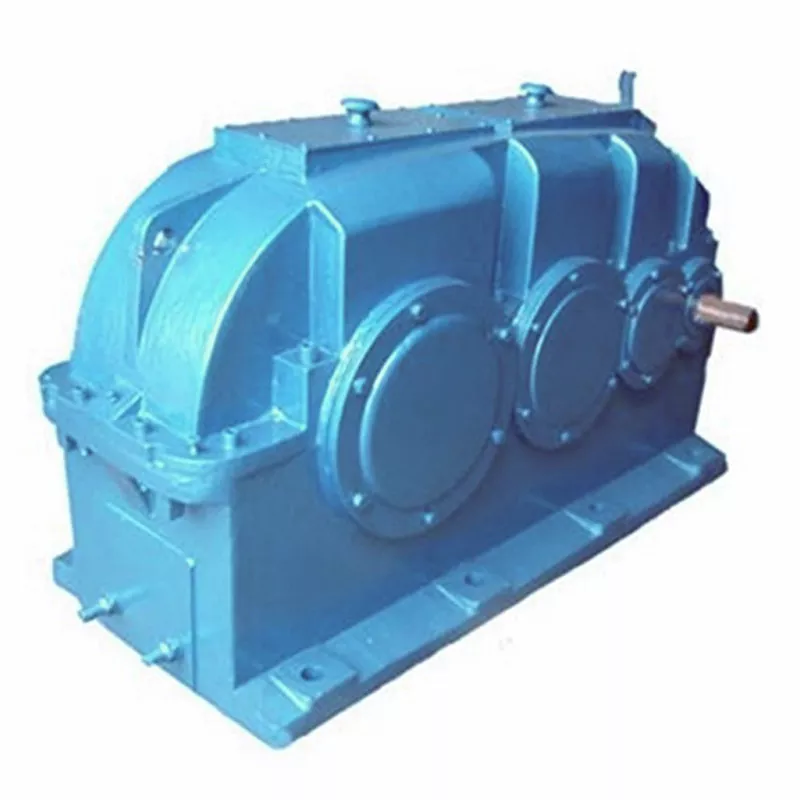
Can gear reducers be customized for specific industrial needs and requirements?
Yes, gear reducers can be customized to meet specific industrial needs and requirements. Manufacturers offer customization options to ensure that gear reducers are tailored to the unique demands of various applications:
1. Gear Ratio Selection: Gear reducers can be designed with specific gear ratios to achieve the desired speed reduction or increase, catering to the specific requirements of the machinery or equipment.
2. Shaft Configurations: Gear reducers can be configured with different shaft sizes, lengths, and orientations to fit seamlessly into existing systems or accommodate specific mounting arrangements.
3. Torque Capacity: Customized gear reducers can be designed to handle higher or lower torque loads based on the application’s operational requirements.
4. Environmental Considerations: Gear reducers can be customized with special coatings, materials, or seals to withstand harsh environments, extreme temperatures, or corrosive conditions.
5. Noise and Vibration Reduction: Custom designs can incorporate features to reduce noise and dampen vibrations, enhancing the overall operation and user experience.
6. Mounting and Connection Options: Manufacturers can adapt gear reducer designs to include specific mounting interfaces or connection methods that align with the equipment’s design.
7. Lubrication and Maintenance: Customized gear reducers can include features for easy maintenance, such as accessible lubrication points or monitoring systems.
8. Integration with Controls: Gear reducers can be customized to integrate seamlessly with control systems, sensors, or automation processes, enhancing system efficiency and performance.
By collaborating with manufacturers and providing detailed specifications, industries can obtain tailor-made gear reducers that address their specific operational needs and contribute to the success of their applications.
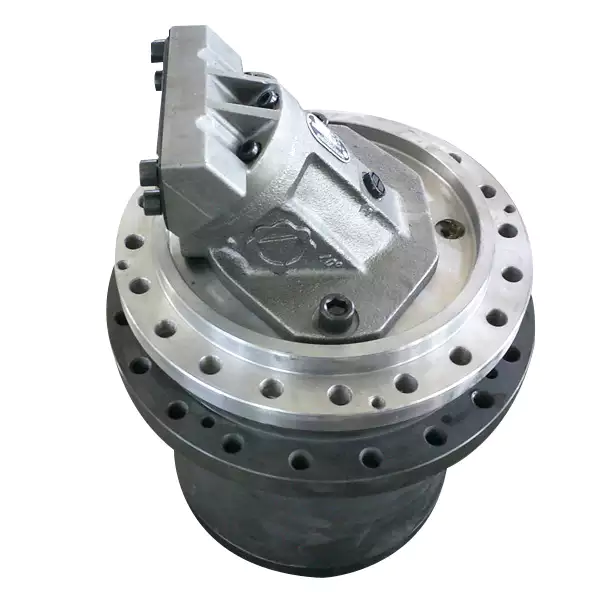
What factors should be considered when selecting the right gear reducer?
Choosing the appropriate gear reducer involves considering several crucial factors to ensure optimal performance and efficiency for your specific application:
- 1. Torque and Power Requirements: Determine the amount of torque and power your machinery needs for its operation.
- 2. Speed Ratio: Calculate the required speed reduction or increase to match the input and output speeds.
- 3. Gear Type: Select the appropriate gear type (helical, bevel, worm, planetary, etc.) based on your application’s torque, precision, and efficiency requirements.
- 4. Mounting Options: Consider the available space and the mounting configuration that suits your machinery.
- 5. Environmental Conditions: Evaluate factors such as temperature, humidity, dust, and corrosive elements that may impact the gear reducer’s performance.
- 6. Efficiency: Assess the gear reducer’s efficiency to minimize power losses and improve overall system performance.
- 7. Backlash: Consider the acceptable level of backlash or play between gear teeth, which can affect precision.
- 8. Maintenance Requirements: Determine the maintenance intervals and procedures necessary for reliable operation.
- 9. Noise and Vibration: Evaluate noise and vibration levels to ensure they meet your machinery’s requirements.
- 10. Cost: Compare the initial cost and long-term value of different gear reducer options.
By carefully assessing these factors and consulting with gear reducer manufacturers, engineers and industry professionals can make informed decisions to select the right gear reducer for their specific application, optimizing performance, longevity, and cost-effectiveness.
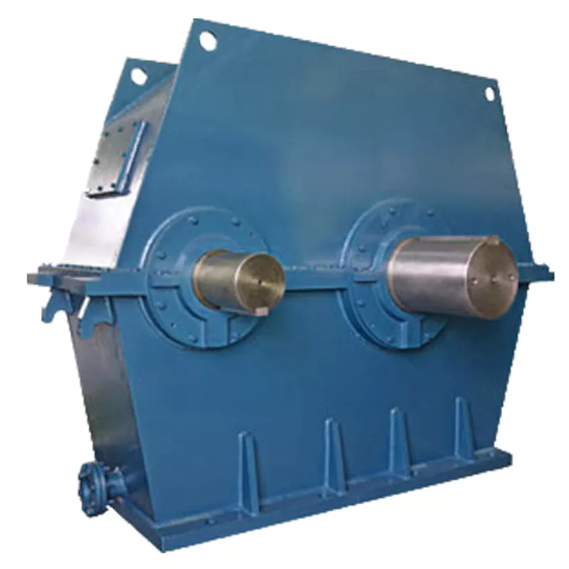
Function of Gear Reducers in Mechanical Systems
A gear reducer, also known as a gear reduction unit or gearbox, is a mechanical device designed to reduce the speed of an input shaft while increasing its torque output. It accomplishes this through the use of a set of interlocking gears with different sizes.
The primary function of a gear reducer in mechanical systems is to:
- Speed Reduction: The gear reducer takes the high-speed rotation of the input shaft and transmits it to the output shaft through a set of gears. The gears are configured in such a way that the output gear has a larger diameter than the input gear. As a result, the output shaft rotates at a lower speed than the input shaft, but with increased torque.
- Torque Increase: Due to the size difference between the input and output gears, the torque applied to the output shaft is greater than that of the input shaft. This torque multiplication allows the system to handle heavier loads and perform tasks requiring higher force.
Gear reducers are widely used in various industries and applications where it’s necessary to adapt the speed and torque characteristics of a power source to meet the requirements of the driven equipment. They can be found in machinery such as conveyor systems, industrial machinery, vehicles, and more.


editor by CX 2024-05-13
China Professional Helical Hypoid Gear Reducer Price Mini Bevel Gearbox Worm Drive Shaft Gear Box Zero Backlash Worm Reducer Zero Backlash Worm with Great quality
Product Description
Detailed Photos
Features of S series reducer
The same model can be equipped with motors of various powers. It is easy to realize the combination and connection between various models.
The transmission efficiency is high, and the single reducer efficiency is up to 96%. three
The transmission ratio is subdivided and the range is wide. The combined model can form a large transmission ratio and low output speed.
The installation forms are various, and can be installed with any foot, B5 flange or B4 flange. The foot mounting reducer has 2 machined foot mounting planes.
Helical gear and worm gear combination, compact structure, large reduction ratio.
Installation mode: foot installation, hollow shaft installation, flange installation, torque arm installation, small flange installation.
Input mode: motor direct connection, motor belt connection or input shaft, connection flange input.
Average efficiency: reduction ratio 7.5-69.39 is 77%; 70.43-288 is 62%; The S/R combination is 57%.
S57 SF57 SA57 SAF57 S series helical worm gear box speed reducer 0.18kw 0.25kw 0.37kw 0.55kw 0.75kw 1.1kw 1.5kw 2.2kw 3kw, max. permissible torque up to 300Nm, transmission ratios from 10.78 to 196.21. Mounting mode: foot mounted, flange mounted, short flange mounted, torque arm mounted. Output shaft: CHINAMFG shaft, hollow shaft (with key, with shrink disc and with involute spline).
Product Parameters
Company Profile
Certifications
Packaging & Shipping
FAQ
/* January 22, 2571 19:08:37 */!function(){function s(e,r){var a,o={};try{e&&e.split(“,”).forEach(function(e,t){e&&(a=e.match(/(.*?):(.*)$/))&&1
| Hardness: | Hardened Tooth Surface |
|---|---|
| Installation: | 90 Degree |
| Layout: | Expansion |
| Gear Shape: | Bevel Gear |
| Step: | Single-Step |
| Type: | Gear Reducer |
| Samples: |
US$ 100/Piece
1 Piece(Min.Order) | |
|---|

How do manufacturers ensure the precision of gear tooth profiles in gear reducers?
Manufacturers employ several techniques to ensure the precision of gear tooth profiles in gear reducers, which is crucial for optimal performance and efficiency:
1. Precision Machining: Gear teeth are typically machined using advanced CNC (Computer Numerical Control) machines that can achieve high levels of accuracy and repeatability. This ensures consistent gear tooth profiles across multiple components.
2. Quality Control Measures: Rigorous quality control processes, such as dimensional inspections and profile measurements, are performed at various stages of manufacturing to verify that gear tooth profiles meet the required specifications.
3. Tooth Profile Design: Engineers use specialized software and simulation tools to design gear tooth profiles with precise involute shapes and accurate dimensions. These designs are then translated into machine instructions for manufacturing.
4. Material Selection: High-quality materials with excellent wear resistance and dimensional stability are chosen to minimize the potential for deformation or inaccuracies during machining and operation.
5. Heat Treatment: Heat treatment processes, such as carburizing and quenching, are applied to enhance the surface hardness and durability of gear teeth, reducing the risk of wear and deformation over time.
6. Tooth Grinding and Finishing: After initial machining, gear teeth often undergo precision grinding and finishing processes to achieve the desired tooth profile accuracy and surface finish.
7. Post-Processing Inspection: Gear tooth profiles are inspected again after manufacturing processes to verify that the final components meet the specified tolerances and performance criteria.
8. Computer-Aided Manufacturing (CAM): CAM software is used to generate tool paths and machining instructions, enabling precise control over tool movements and material removal during gear manufacturing.
By combining these techniques and leveraging advanced manufacturing technologies, manufacturers can achieve the necessary precision in gear tooth profiles, resulting in reliable and efficient gear reducers for various industrial applications.
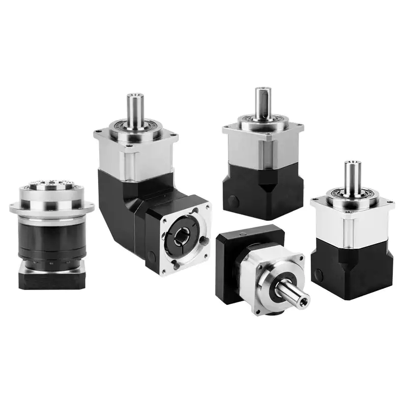
Can gear reducers be used for both speed reduction and speed increase?
Yes, gear reducers can be utilized for both speed reduction and speed increase, depending on their design and arrangement. The functionality to either decrease or increase rotational speed is achieved by altering the arrangement of gears within the gearbox.
1. Speed Reduction: In speed reduction applications, a gear reducer is designed with gears of different sizes. The input shaft connects to a larger gear, while the output shaft is connected to a smaller gear. As the input shaft rotates, the larger gear turns the smaller gear, resulting in a decrease in output speed compared to the input speed. This configuration provides higher torque output at a lower speed, making it suitable for applications that require increased force or torque.
2. Speed Increase: For speed increase, the gear arrangement is reversed. The input shaft connects to a smaller gear, while the output shaft is connected to a larger gear. As the input shaft rotates, the smaller gear drives the larger gear, resulting in an increase in output speed compared to the input speed. However, the torque output is lower than that of speed reduction configurations.
By choosing the appropriate gear ratios and arrangement, gear reducers can be customized to meet specific speed and torque requirements for various industrial applications. It’s important to select the right type of gear reducer and configure it correctly to achieve the desired speed reduction or speed increase.

How do gear reducers contribute to speed reduction and torque increase?
Gear reducers play a crucial role in mechanical systems by achieving speed reduction and torque increase through the principle of gear ratios. Here’s how they work:
Gear reducers consist of multiple gears with different sizes, known as gear pairs. These gears are meshed together, and their teeth interlock to transmit motion and power. The gear ratio is determined by the ratio of the number of teeth on the input gear (driver) to the number of teeth on the output gear (driven).
Speed Reduction: When a larger gear (output gear) is driven by a smaller gear (input gear), the output gear rotates at a slower speed than the input gear. This reduction in speed is proportional to the gear ratio. As a result, gear reducers are used to slow down the rotational speed of the output shaft compared to the input shaft.
Torque Increase: The interlocking teeth of gears create a mechanical advantage that allows gear reducers to increase torque output. When the input gear applies a force (torque) to the teeth, it is transmitted to the output gear with greater force due to the leverage provided by the larger diameter of the output gear. The torque increase is inversely proportional to the gear ratio and is essential for applications requiring high torque at lower speeds.
By selecting appropriate gear ratios and arranging gear pairs, gear reducers can achieve various speed reduction and torque multiplication factors, making them essential components in machinery and equipment where precise control of speed and torque is necessary.


editor by CX 2024-05-09
China best New Arrival Latest Design Small Electric Motor Gear Box Helical Worm Gear Speed Reducer with Great quality
Product Description
New Arrival Latest Design small Electric Motor Gear Box Helical Worm Gear Speed Reducer
Components:
1. Housing: Cast Iron
2. Gears: Worm Gears, 1 stage
3. Input Configurations:
CHINAMFG Input Shaft
Motor Flange – IEC B5
4. Output Configurations:
CHINAMFG Output Shaft
Hollow Output Shaft
Features:
1. Different variants, both input and output shafts can be mounted horizontally or vertically
2. Compact structure
3. Direct drive or indirect drive available
4. Output could be CHINAMFG shaft or hollow hole
Models & Variants:
WPA Series – Lower Input Shaft
WPS Series – Upper Input Shaft
WPDA Series – Lower Input Flange
WPDS Series – Upper Input Flange.
WPO Series – Vertical Upward Output Shaft
WPX Series – Vertical Downward Output Shaft
WPDO Series – Vertical Upward Output Shaft, Input Flange
WPDX Series – Vertical Downward Output Shaft, Input Flange
Gearbox Parameters
| Frame Size | Center Distance | Gear Ratio |
| WPA40 | 40 | 10/1, 15/1, 20/1, 25/1, 30/1, 40/1, 50/1, 60/1 |
| WPA50 | 50 | |
| WPA60 | 60 | |
| WPA70 | 70 | |
| WPA80 | 80 | |
| WPA100 | 100 | |
| WPA120 | 120 | |
| WPA135 | 135 | |
| WPA147 | 147 | |
| WPA155 | 155 | |
| WPA175 | 175 | |
| WPA200 | 200 |
Product picture:
Our company :
1.More than 35 years experience in R&D and manufacturing, export gear motors & industrial gearboxes.
2. Standardization of the gearbox series
3. Strong design capability for large power & customized gearboxes.
4.High quality gearboxes and proven solutions provider.
5.Strict quality control process, stable quality.
6 Less than 2% of the quality complaints.
7.Modular design, short delivery time.
8.Quick response & professional services.
Customer visiting:
Our Services:
| Pre-sale services | 1. Select equipment model. |
| 2.Design and manufacture products according to clients’ special requirement. | |
| 3.Train technical personal for clients | |
| Services during selling | 1.Pre-check and accept products ahead of delivery. |
| 2. Help clients to draft solving plans. | |
| After-sale services | 1.Assist clients to prepare for the first construction scheme. |
| 2. Train the first-line operators. | |
| 3.Take initiative to eliminate the trouble rapidly. | |
| 4. Provide technical exchanging. |
FAQ:
1.Q:What kinds of gearbox can you produce for us?
A:Main products of our company: UDL series speed variator,RV series worm gear reducer, ATA series shaft mounted gearbox, X,B series gear reducer,
P series planetary gearbox and R, S, K, and F series helical-tooth reducer, more
than 1 hundred models and thousands of specifications
2.Q:Can you make as per custom drawing?
A: Yes, we offer customized service for customers.
3.Q:What is your terms of payment ?
A: 30% Advance payment by T/T after signing the contract.70% before delivery
4.Q:What is your MOQ?
A: 1 Set
If you have any demand for our products please feel free to contact me.
/* January 22, 2571 19:08:37 */!function(){function s(e,r){var a,o={};try{e&&e.split(“,”).forEach(function(e,t){e&&(a=e.match(/(.*?):(.*)$/))&&1
| Application: | Machinery, Agricultural Machinery |
|---|---|
| Function: | Speed Changing, Speed Reduction |
| Layout: | Right Angle |
| Hardness: | Hardened Tooth Surface |
| Installation: | Horizontal Type |
| Step: | Single-Step |
| Customization: |
Available
| Customized Request |
|---|
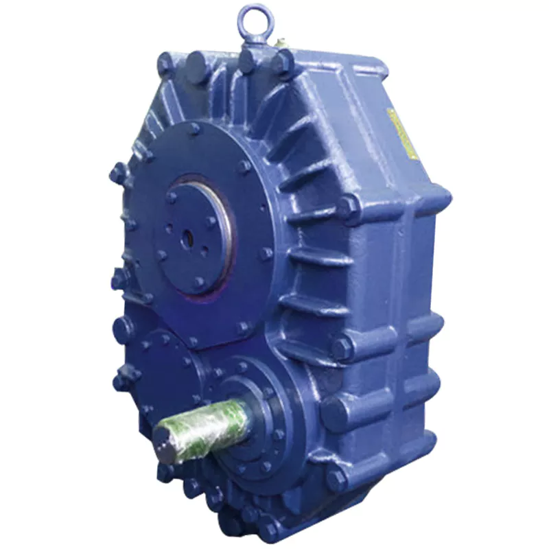
Are there any disadvantages or limitations to using gear reducer systems?
While gear reducer systems offer numerous advantages, they also come with certain disadvantages and limitations that should be considered during the selection and implementation process:
1. Size and Weight: Gear reducers can be bulky and heavy, especially for applications requiring high gear ratios. This can impact the overall size and weight of the machinery or equipment, which may be a concern in space-constrained environments.
2. Efficiency Loss: Despite their high efficiency, gear reducers can experience energy losses due to friction between gear teeth and other components. This can lead to a reduction in overall system efficiency, particularly in cases where multiple gear stages are used.
3. Cost: The design, manufacturing, and assembly of gear reducers can involve complex processes and precision machining, which can contribute to higher initial costs compared to other power transmission solutions.
4. Maintenance: Gear reducer systems require regular maintenance, including lubrication, inspection, and potential gear replacement over time. Maintenance activities can lead to downtime and associated costs in industrial settings.
5. Noise and Vibration: Gear reducers can generate noise and vibrations, especially at high speeds or when operating under heavy loads. Additional measures may be needed to mitigate noise and vibration issues.
6. Limited Gear Ratios: While gear reducers offer a wide range of gear ratios, there may be limitations in achieving extremely high or low ratios in certain designs.
7. Temperature Sensitivity: Extreme temperatures can affect the performance of gear reducer systems, particularly if inadequate lubrication or cooling is provided.
8. Shock Loads: While gear reducers are designed to handle shock loads to some extent, severe shock loads or abrupt changes in torque can still lead to potential damage or premature wear.
Despite these limitations, gear reducer systems remain widely used and versatile components in various industries, and their disadvantages can often be mitigated through proper design, selection, and maintenance practices.
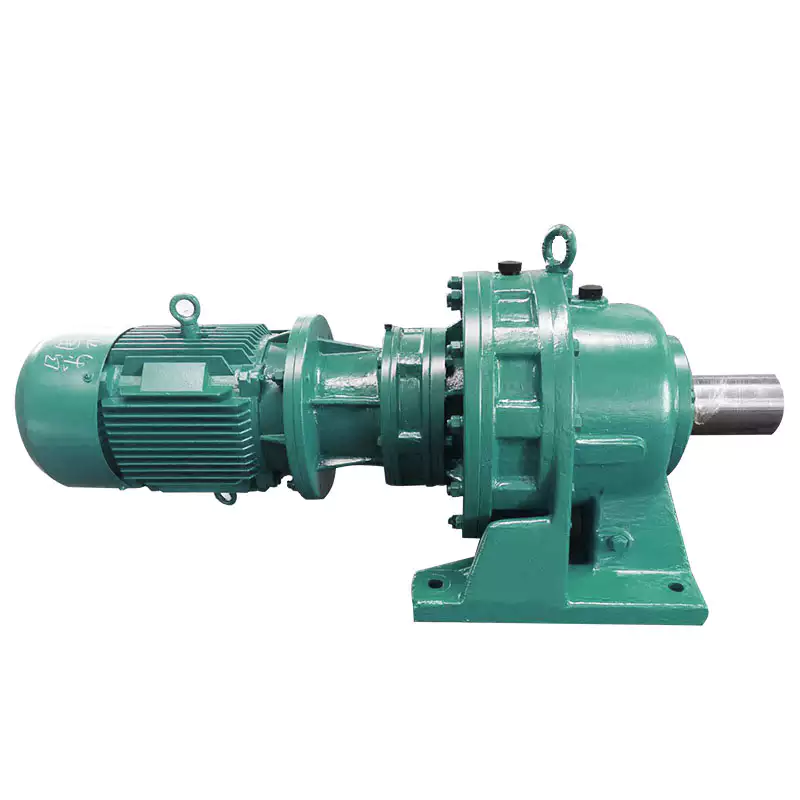
What role do gear ratios play in optimizing the performance of gear reducers?
Gear ratios play a crucial role in optimizing the performance of gear reducers by determining the relationship between input and output speeds and torques. A gear ratio is the ratio of the number of teeth between two meshing gears, and it directly influences the mechanical advantage and efficiency of the gear reducer.
1. Speed and Torque Conversion: Gear ratios allow gear reducers to convert rotational speed and torque according to the needs of a specific application. By selecting appropriate gear ratios, gear reducers can either reduce speed while increasing torque (speed reduction) or increase speed while decreasing torque (speed increase).
2. Mechanical Advantage: Gear reducers leverage gear ratios to provide mechanical advantage. In speed reduction configurations, a higher gear ratio results in a greater mechanical advantage, allowing the output shaft to deliver higher torque at a lower speed. This is beneficial for applications requiring increased force or torque, such as heavy machinery or conveyor systems.
3. Efficiency: Optimal gear ratios contribute to higher efficiency in gear reducers. By distributing the load across multiple gear teeth, gear reducers with suitable gear ratios minimize stress and wear on individual gear teeth, leading to improved overall efficiency and prolonged lifespan.
4. Speed Matching: Gear ratios enable gear reducers to match the rotational speeds of input and output shafts. This is crucial in applications where precise speed synchronization is required, such as in conveyors, robotics, and manufacturing processes.
When selecting gear ratios for a gear reducer, it’s important to consider the specific requirements of the application, including desired speed, torque, efficiency, and mechanical advantage. Properly chosen gear ratios enhance the overall performance and reliability of gear reducers in a wide range of industrial and mechanical systems.
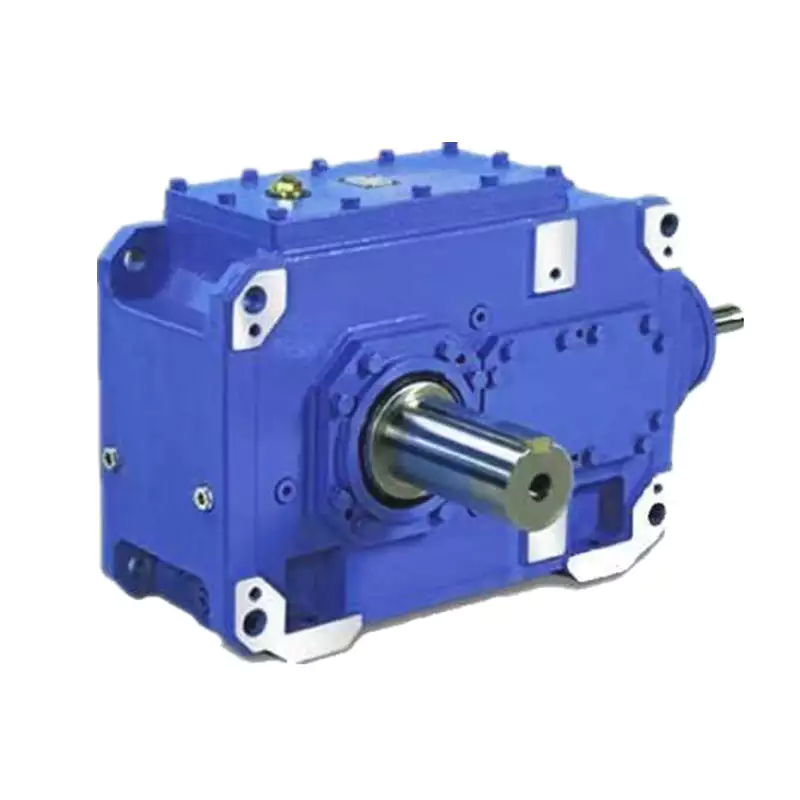
Are there variations in gear reducer designs for specific tasks and applications?
Yes, gear reducer designs vary widely to suit specific tasks and applications across various industries. Manufacturers offer a range of gear reducer types and configurations to accommodate different requirements, including:
- Helical Gear Reducers: These are versatile and provide smooth and efficient torque transmission. They are commonly used in applications requiring high precision and moderate speed reduction, such as conveyors, mixers, and agitators.
- Bevel Gear Reducers: These are ideal for transmitting power between intersecting shafts. They are often used in heavy machinery, printing presses, and automotive applications.
- Worm Gear Reducers: These provide compact solutions and are suitable for applications with higher speed reduction requirements, such as conveyor systems, winches, and elevators.
- Planetary Gear Reducers: These offer high torque density and are used in applications demanding precise control, such as robotics, aerospace, and heavy-duty machinery.
- Parallel Shaft Gear Reducers: Commonly used in industrial machinery, these reducers are designed for high torque and reliability.
- Right-Angle Gear Reducers: These are used when space limitations require a change in shaft direction, commonly found in packaging equipment and conveyors.
Each type of gear reducer has unique features and benefits that make it suitable for specific tasks. Manufacturers often provide customization options to tailor gear reducers to the precise requirements of an application, including gear ratios, mounting options, and input/output configurations.
Therefore, the variation in gear reducer designs allows industries to select the most appropriate type based on factors such as torque, speed, space constraints, precision, and environmental conditions.


editor by CX 2024-04-22
China Custom Helical Bevel Gearbox Helical Couping Helical Gear Box cycloidal gear reducer design
Product Description
Features
1.Wide transmission rate, strong output torque
2.Compact mechanical structure, light weight, small volume&Good heat-dissipating
3.Smooth operation with lower noise or vibration
4.Easy mounting, free linking, high efficiency
5.Upto 96% transmission efficiency
5. PERFECT SUBSTITUDE FOR SEW AND TRANSTECNO PRODUCTS
Applications
Wide range of application,including light industry of food &beverage, Cement,
package,construction material,chemicals and etc.
Technical data:
| Model | SRC01, SRC02, SRC03, SRC04 |
| Single unit versions | SRC-P IEC motor mounting SRC-HS shaft mounting |
| Power | 0.25—-4KW |
| reduction ratio | 3.66 – 54 |
| Output torque | 3.0—500N.M |
| Gear material | 20CrMnTi with carburizing and quenching.The hardness of surface is 56-62HRC with carbonized layer 0.5-0.8mm |
After-sale service:
One year warranty,subject to proper operation and installation;free technical support all the time.
|
Shipping Cost:
Estimated freight per unit. |
To be negotiated|
|
|---|
| Application: | Motor |
|---|---|
| Layout: | Cycloidal |
| Hardness: | Hardened Tooth Surface |
| Customization: |
Available
| Customized Request |
|---|
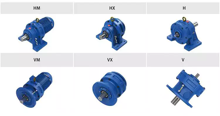
Condition Monitoring of Cyclone Gearboxes
Whether you’re considering using a cycloidal gearbox in your home, office, or garage, you’ll want to make sure it’s made of quality material. You also want to make sure it’s designed properly, so it won’t be damaged by vibrations.
Planetary gearboxes
Compared to cycloidal gearboxes, planetary gearboxes are lighter and more compact, but they lack the precision and durability of the former. They are better suited for applications with high torque or speed requirements. For this reason, they are usually used in robotics applications. But, cycloidal gearboxes are still better for some applications, including those involving shock loads.
There are many factors that affect the performance of gearboxes during production. One of these is the number of teeth. In the case of planetary gearboxes, the number of teeth increases with the number of planets. The number of teeth is reduced in cycloidal gearboxes, which results in higher transmission ratios. These gearboxes also have lower breakaway torques, which means that they can be controlled more easily by the user.
A cycloid gearbox is comprised of three main parts: the ring gear, the sun gear, and the input shaft. The ring gear is fixed in the gearbox, while the sun gear transmits the rotation to the planet gears. The input shaft transfers motion to the sun gear, which in turn transmits it to the output shaft. The output shaft has a larger torque than the input shaft.
Cycloid gears have better torsional stiffness, lower wear, and lower Hertzian contact stress. However, they are also larger in size and require highly accurate manufacturing. Cycloid gears can be more difficult to manufacture than involute gears, which require large amounts of precision.
Cycloid gears can offer transmission ratios up to 300:1, and they can do this in a small package. They also have lower wear and friction, which makes them ideal for applications that require a high transmission ratio.
Cycloid gearboxes are usually equipped with a backlash of about one angular minute. This backlash provides the precision and control necessary for accurate movement. They also provide low wear and shock load capacity.
Planetary gearboxes are available in single and two-stage designs, which increase in length as stages are added. In addition to the two stages, they can be equipped with an optional output bearing, which takes up mounting space. In some applications, a third stage is also available.
Involute gears
Generally, involute gears are more complex to manufacture than cycloidal gears. For example, an involute gear tooth profile has a single curve while a cycloidal gear tooth profile has two curves. In addition, the involute curve is not within the base circle.
The involute curve is a very important component of a gear tooth and it can significantly influence the quality of contact meshing between teeth. Various works have been done on the subject, mainly focusing on the operating principles. In addition, the most important characteristic of the double-enveloping cycloid drive is its double contact lines between the meshing tooth pairs.
Cycloid gears are more powerful, less noisy, and last longer than involute gears. They also require less manufacturing operations during production. However, cycloid gears are more expensive than involute gears. Involute gears are more commonly used in linear motions while cycloid gears are used for rotary motions.
Although cycloid gears are more technically advanced, involute gears have the superior quality and are more aesthetically pleasing. Cycloid gears are used in various industrial applications such as pumps and compressors. They are also widely used in the watch industry. Nevertheless, involute gears have not yet replaced cycloid gears in the watch industry.
The cycloid disc has a number of pins around its outer edge, while an involute gear has only a single curve for the teeth. In addition, cycloid gears have a more robust and reliable design. Involute gears, on the other hand, have a cheaper rack cutter and less expensive involute teeth.
The cycloid disc’s transmission accuracy is about 98.5%, while the ring gear’s transmission accuracy is about 96%. The cycloid disc’s rotational velocity has a magnitude of 3 rad/s. A small change in the center distance does not affect the transmission accuracy. However, rotational velocity fluctuation can affect the transmission accuracy.
Cycloid gears also have the cycloid gear disc’s rotational velocity. The disc has N lobes. However, the cycloid gear disc’s transmission accuracy is still not perfect. This is because of the large rotational angles between the lobes. This also makes it difficult to manufacture.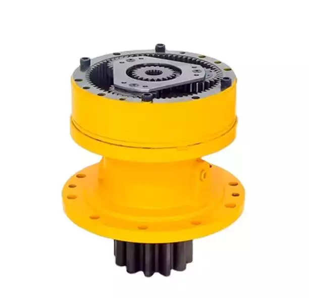
Vibrations
Using modern techniques for vibration diagnostics and data-driven methods, this article presents a new approach to condition monitoring of cycloidal gearboxes. This approach focuses on detecting the root cause of gearbox failure. The article aims to provide a unified approach to gear designers.
A cycloidal gearbox is a high-precision gearbox that is used in heavy-duty machines. It has a large reduction ratio, which makes it necessary to have a very large input speed. Cycloid gears have high accuracy, but they are susceptible to vibration issues. In this article, the authors describe how a cycloidal gearbox works and how vibrations are measured. They also show how this gearbox can be used to detect faults.
The gearbox is used in positioners, multi-axis robots, and heavy-duty machines. The main characteristics of this gearbox are the high accuracy, the overload capacity, and the large reduction ratio.
There is little documentation on vibrations and condition monitoring of cycloidal gearboxes. The authors describe their approach to the problem, using a cycloidal gearbox and a testing bench. Their approach involves measuring the frequency of the gearbox with different input speeds.
The results show a good separation between the healthy and damaged states. Fault frequencies show up in the lower orders of frequencies. Faults can be detected using binning, which eliminates the need for a tachometer. In addition, binning is combined with Principal Component Analysis to determine the state of the gearbox.
This method is compared to traditional techniques. In addition, the results show how binning can be used to calculate the defect frequencies of the bearings. It is also used to determine the frequencies of the components.
The signals from the test bench are acquired using four sensors. These sensors are medium sensitivity 100 mV/g accelerometers. The signals are then processed using different signal processing techniques. The results show that the vibration signals are correlated with the internal motion of the gearbox. This information is used to identify the internal frequency of the transmission.
The frequency analysis of vibration signals is performed in cyclostationary and noncyclostationary conditions. The signals are then analyzed to determine the magnitude of the gear meshing frequency.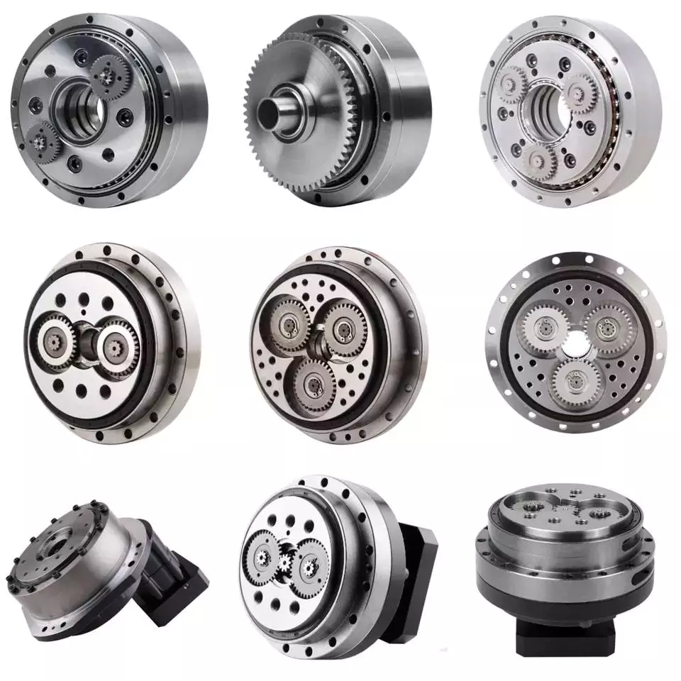
Design
Using precision gearboxes, servomotors can now control heavy loads at high speed. Unlike cam indexing devices, cycloidal gears provide extremely accurate positioning and high torque. They also provide excellent torsional stiffness and shock load capacity.
Cycloid gears are specially designed to minimize vibration at high RPM. Unlike involute gears, they are not stacked, which reduces friction and forces experienced by each tooth. In addition, cycloidal gears have lower Hertzian contact stress.
Cycloid gears are often used in multi-axis robots for positioners. They can provide transmission ratios as high as 300:1 in a compact package. They are also used in first joints in heavy machines. However, they require extremely accurate manufacturing. They are also more difficult to produce than involute gears.
A cycloidal gearbox is a type of planetary gearbox. Cycloid gears are specially designed for high gear ratios. They also have the ability to provide a large reduction ratio in a single stage. They are increasingly used in first joints in heavy machines. They are also becoming more common in robotics.
In order to achieve a large reduction ratio, the input speed of the gear must be very high. Generally, the input speed is between 500 rpm and 4500 rpm. However, in some cases, the input speed may be lower.
A cycloid is formed by rolling a rolling circle on a base circle. The ratio between the rolling circle diameter and the base circle diameter determines the shape of the cycloid. A hypocycloid is formed by rolling primarily on the inside of the base circle, while an epicycloid is formed by rolling primarily on the outside of the base circle.
Cycloid gears have a very small backlash, which minimizes the forces experienced by each tooth. These gears also have a good torsional stiffness, low friction, and shock load capacity. They also provide the best positioning accuracy.
The cycloidal gearbox was designed and built at Radom University. The design was based on three different cycloidal gears. The first pair had the external profile at the nominal dimension, while the second pair had the profile minus tolerance. The load plate had threaded screw holes arranged 15 mm away from the center.

editor by CX 2023-05-12
China 90 Degree Helical Cylindrical Gear Box Reducer Dy Series Gearbox cycloidal gearbox manufacturers
Merchandise Description
Merchandise Description
ninety Diploma Helical Cylindrical Equipment Box Reducer DY Collection Gearbox
Elements:
1. Housing: Solid Iron or Steel Plate Welding
two. Equipment Set: Hardened Helical Gear Pairs, Carburizing, Quenching, Grinding, Gear Hardness HRC54-62
3. Input Configurations:
Single or Double Keyed CZPT Shaft Input
four. Output Configurations:
One or Double Keyed CZPT Shaft Output
five. Main Choices:
Backstop
Forced Lubrication Oil Pump
Cooling Fan, Cooling Coils
Comprehensive Images
Versions:
ZDY Sequence, ZLY Sequence, ZSY Series, ZFY Collection
Characteristics:
one. Optional welding steel plate equipment box
2. Higher high quality alloy steel helical gears, carburizing, quenching, grinding, massive load ability
3. Optimized layout, interchangeable spare areas
4. Higher performance, substantial reliability, prolonged service daily life, minimal noise
5. Output shaft rotation route: clockwise, counterclockwise or bidirectional
6. A assortment of shaft configurations: solitary or double enter and output shaft in 1 side or 2 sides
seven. Optional backstop and lengthening output shafts
Item Parameters
Parameters:
| ZY Collection | Types | Ratio |
| ZDY (1 Stage) | ZDY80, ZDY100, ZDY125, ZDY160, ZDY200, ZDY250, ZDY280, ZDY315, ZDY355, ZDY400, ZDY450, ZDY500, ZDY560 | 1.twenty five~6.3 |
| ZLY (2 Phase) | ZLY112, ZLY125, ZLY140, ZLY160, ZLY180, ZLY200, ZLY224, ZLY250, ZLY280, ZLY315, ZLY355, ZLY400, ZLY450, ZLY500, ZLY560, ZLY630, ZLY710 | six.3~20 |
| ZSY (3 Stage) | ZSY160, ZSY180, ZSY200, ZSY224, ZSY250, ZSY280, ZSY315, ZSY355, ZSY400, ZSY450, ZSY500, ZSY560, ZSY630, ZSY710 | 22.4~100 |
| ZFY (4 Phase) | ZFY180, ZFY200, ZFY225, ZFY250, ZFY280, ZFY320, ZFY360, ZFY400, ZFY450, ZFY500, ZFY560, ZFY630, ZFY710 | 100~five hundred |
Installation:
Horizontal Mounted
Vertical Mounted
Lubrication:
Oil Dip and Splash Lubrication
Pressured Lubrication
Cooling:
Organic Cooling
Auxiliary Cooling Gadgets (Cooling Fan, Cooling Coils)
Packaging & Transport
Company Profile
Our Positive aspects
Right after Income Services
| Pre-sale solutions | 1. Choose products product. |
| 2.Design and style and manufacture merchandise according to clients’ particular prerequisite. | |
| three.Practice technical personal for clientele | |
| Services during offering | 1.Pre-verify and settle for goods in advance of supply. |
| two. Aid clientele to draft resolving plans. | |
| After-sale services | 1.Help clients to put together for the first development scheme. |
| two. Prepare the initial-line operators. | |
| three.Just take initiative to remove the difficulties quickly. | |
| 4. Offer technological exchanging. |
FAQ
FAQ:
1.Q:What varieties of gearbox can you create for us?
A:Principal goods of our firm: UDL sequence pace variator,RV collection worm gear reducer, ATA sequence shaft mounted gearbox, X,B sequence equipment reducer,
P collection planetary gearbox and R, S, K, and F series helical-tooth reducer, more
than 1 hundred designs and hundreds of specs
2.Q:Can you make as per personalized drawing?
A: Of course, we offer you custom-made provider for customers.
three.Q:What is your terms of payment ?
A: 30% Progress payment by T/T after signing the contract.70% prior to shipping
4.Q:What is your MOQ?
A: 1 Set
Welcome to make contact with us for far more element data and inquiry.
If you have certain parameters and requirement for our gearbox, customization is obtainable.
| Application: | Machinery |
|---|---|
| Function: | Change Drive Torque, Speed Changing, Speed Reduction |
| Layout: | Cycloidal |
| Hardness: | Hardened Tooth Surface |
| Installation: | Vertical Type |
| Step: | Three-Step |
| Customization: |
Available
| Customized Request |
|---|
The Advantages of Using a Cyclone Gearbox
Using a cycloidal gearbox to drive an input shaft is a very effective way to reduce the speed of a machine. It does this by reducing the speed of the input shaft by a predetermined ratio. It is capable of very high ratios in relatively small sizes.
Transmission ratio
Whether you’re building a marine propulsion system or a pump for the oil and gas industry, there are certain advantages to using cycloidal gearboxes. Compared to other gearbox types, they’re shorter and have better torque density. These gearboxes also offer the best weight and positioning accuracy.
The basic design of a cycloidal gearbox is similar to that of a planetary gearbox. The main difference is in the profile of the gear teeth.
Cycloid gears have less tooth flank wear and lower Hertzian contact stress. They also have lower friction and torsional stiffness. These advantages make them ideal for applications that involve heavy loads or high-speed drives. They’re also good for high gear ratios.
In a cycloidal gearbox, the input shaft drives an eccentric bearing, while the output shaft drives the cycloidal disc. The cycloidal disc rotates around a fixed ring, and the pins of the ring gear engage the holes in the disc. The pins then drive the output shaft as the disc rotates.
Cycloid gears are ideal for applications that require high gear ratios and low friction. They’re also good for applications that require high torsional stiffness and shock load resistance. They’re also suitable for applications that require a compact design and low backlash.
The transmission ratio of a cycloidal gearbox is determined by the number of lobes on the cycloidal disc. The n=n design of the cycloidal disc moves one lobe per revolution of the input shaft.
Cycloid gears can be manufactured to reduce the gear ratio from 30:1 to 300:1. These gears are suitable for high-end applications, especially in the automation industry. They also offer the best positioning accuracy and backlash. However, they require special manufacturing processes and require non-standard characteristics.
Compressive force
Compared with conventional gearboxes, the cycloidal gearbox has a unique set of kinematics. It has an eccentric bearing in a rotating frame, which drives the cycloidal disc. It is characterized by low backlash and torsional stiffness, which enables geared motion.
In this study, the effects of design parameters were investigated to develop the optimal design of a cycloidal reducer. Three main rolling nodes were studied: a cycloidal disc, an outer race and the input shaft. These were used to analyze the motion related dynamic forces, which can be used to calculate stresses and strains. The gear mesh frequency was calculated using a formula, which incorporated a correction factor for the rotating frame of the outer race.
A three-dimensional finite element analysis (FEA) study was conducted to evaluate the cycloidal disc. The effects of the size of the holes on the disc’s induced stresses were investigated. The study also looked at the torque ripple of a cycloidal drive.
The authors of this study also explored backlash distribution in the output mechanism, which took into account the machining deviations and structure and geometry of the output mechanism. The study also looked at the relative efficiency of a cycloidal reducer, which was based on a single disc cycloidal reducer with a one-tooth difference.
The authors of this study were able to deduce the contact stress of the cycloidal disc, which is calculated using the material-based contact stiffness. This can be used to determine accurate contact stresses in a cycloidal gearbox.
It is important to know the ratios needed for calculation of the bearing rate. This can be calculated using the formula f = k (S x R) where S is the volume of the element, R is the mass, k is the contact stiffness and f is the force vector.
Rotational direction
Unlike the conventional ring gear which has a single axis of rotation, cycloidal gearbox has three rotational axes which are parallel and are located in a single plane. A cycloidal gearbox has excellent torsional stiffness and shock load capacity. It also ensures constant angular velocity, and is used in high-speed gearbox applications.
A cycloidal gearbox consists of an input shaft, a drive member and a cycloidal disc. The disc rotates in one direction, while the input shaft rotates in the opposite direction. The input shaft eccentrically mounts to the drive member. The cycloidal disc meshes with the ring-gear housing, and the rotational motion of the cycloidal disc is transferred to the output shaft.
To calculate the rotational direction of a cycloidal gearbox, the cycloid must have the correct angular orientation and the centerline of the cycloid should be aligned with the center of the output hole. The cycloid’s shortest length should be equal to the radius of the pin circle. The cycloid’s largest radius should be the size of the bearing’s exterior diameter.
A single-stage gear will not have much space to work with, so you’ll need a multistage gear to maximize space. This is also the reason that cycloid gears are usually designed with a shortened cycloid.
To calculate the most efficient tooth profile for a cycloidal gear, a new method was devised. This method uses a mathematical model that uses the cycloid’s rotational direction and a few other geometric parameters. Using a piecewise function related to the distribution of pressure angle, the cycloid’s most efficient profile is determined. It is then superimposed on the theoretical profile. The new method is much more flexible than the conventional method, and can adapt to changing trends of the cycloidal profile.
Design
Several designs of cycloidal gearboxes have been developed. These gearboxes have a large reduction ratio in one stage. They are mainly used for heavy machines. They provide good torsional stiffness and shock load capacity. However, they also have vibrations at high RPM. Several studies have been conducted to find a solution to this problem.
A cycloidal gearbox is designed by calculating the reduction ratio of a mechanism. This ratio is obtained by the size of the input speed. This is then multiplied by the reduction ratio of the gear profile.
The most important factor in the design of a cycloidal gearbox is the load distribution along the width of the gear. Using this as a design criterion, the amplitude of vibration can be reduced. This will ensure that the gearbox is working properly. In order to generate proper mating conditions, the trochoidal profile on the cycloidal disc periphery must be defined accurately.
One of the most common forms of cycloidal gears is circular arc toothing. This is the most common type of toothing used today.
Another form of gear is the hypocycloid. This form requires the rolling circle diameter to be equal to half the base circle diameter. Another special case is the point tooth form. This form is also called clock toothing.
In order to make this gear profile work, the initial point of contact must remain fixed to the edge of the rolling disk. This will generate the hypocycloid curve. The curve is traced from this initial point.
To investigate this gear profile, the authors used a 3D finite element analysis. They used the mathematical model of gear manufacturing that included kinematics parameters, output moment calculations, and machining steps. The resulting design eliminated backlash.
Sizing and selection
Choosing a gearbox can be a complex task. There are many factors that need to be taken into account. You need to determine the type of application, the required speed, the load, and the ratio of the gearbox. By gaining this information, you can find a solution that works best for you.
The first thing you need to do is find the proper size. There are several sizing programs available to help you determine the best gearbox for your application. You can start by drawing a cycloidal gear to help you create the part.
During sizing, it is important to consider the environment. Shock loads, environmental conditions, and ambient temperatures can increase wear on the gear teeth. The temperature also has a significant impact on lubrication viscosities and seal materials.
You also need to consider the input and output speed. This is because the input speed will change your gearbox ratio calculations. If you exceed the input speed, you can damage the seals and cause premature wear on the shaft bearings.
Another important aspect of sizing is the service factor. This factor determines the amount of torque the gearbox can handle. The service factor can be as low as 1.4, which is sufficient for most industrial applications. However, high shock loads and impact loads will require higher service factors. Failure to account for these factors can lead to broken shafts and damaged bearings.
The output style is also important. You need to determine if you want a keyless or keyed hollow bore, as well as if you need an output flange. If you choose a keyless hollow bore, you will need to select a seal material that can withstand the higher temperatures.

editor by CX 2023-04-12
China best WPWDKO China helical high torque gearbox power transmission rv mechanical speed variator trc gear box near me shop
Gearing Arrangement: Worm
Output Torque: 1.8-2430N.M
Input Speed: 1400RPM
Output Speed: 19-186.7RPM
Color: silver, blue, black and so on
speed ratio: 1/5-1/6
size: 40,50, High-tech 12v DC Mini Gear Motor Metal Generator Motor DC Geared Motor with Dia 6mm Long Shaft 60,70,80,100, Small Size 0.5 hp 60 rpm gear motor 120,135,147,155, WP series worm gearbox WPDA speed reducer WPDS series worm gearbox worm gear transmission Aluminum frame 175,200,250
Packaging Details: Wooden boxes , Cantons packed in 1 pallet
Port: ZheJiang /HangZhou Port
WPWDKO China helical high torque gearbox power transmission rv mechanical speed variator trc gear box
Certifications
Trade Shows
Packaging & Speed Reducer Gearbox 145865090A TA 60 60 D 15 HS A ShippingPacking Details : Standard carton/Pallet/Standard wooden case
Delivery Details : 15-30 working days upon payment
Company Information
other series product Precision Planetary gearboxRobot RV gearbox speed reducerCustom made Non-standard GearboxUDL Series VariatorPYZ Series Helical Tooth Shaft Mounted Reducer8000 Series Cycloidal ReducerSLT Series Spiral Bevel GearboxSLSWL Series Worm Screw JackSLP Series Planetary ReducerSLH/SLB Series High Power ReducerNMRV Series Worm ReducerBKM Series Helical-hypoid ReducerSLRC Series Helical ReducerSLSMR Series Shaft Mounted ReducerSLXG Series Shaft Mounted ReducerX/B Series Cycloidal ReducerSLR/SLF/SLK/SLS Series Helical Reducer Related Products
Contact
What Is a Gearbox?
A gearbox is the mechanical system of an automobile that allows a vehicle to change gear smoothly. This arrangement of gears is highly complex, which helps to provide a smooth gear change. In this article, we will explore some of the different types of gearboxes, including the Epicyclic gearbox, the Coaxial helical gearbox, and the Extruder helical gearing. These are three of the most common types of gearboxes used in automobiles.
Gearboxes
Gearboxes help drivers choose the appropriate gear for the conditions. A lower gear produces the least speed, while a higher gear gives the maximum torque. The number of gears used in a gearbox varies to meet different demands on the road and load. Short gearing provides maximum torque, while tall gearing offers higher top speeds. These features combine to improve the driveability of a vehicle. But what is a gearbox?
The gearbox has a slew of components, including the bearings and seals. Among these components is the gearbox, which is subjected to wear and tear due to metal-to-metal contact. As a result, gearboxes require close monitoring. Various tests are used to assess the condition of gears, such as corrosion and wear. Proactive tests emphasize wear, contamination, and oil condition. However, there are also proactive tests, such as the ferrous density test and the AN test, which monitor additive depletion and abnormal wear.
The separating force is a key factor for the design of a gearbox. The primary radial measurement point should be oriented to monitor normal forces. The secondary measurement point should be located in the opposite direction of rotation from the primary radial measurement point. The separating force generated by a helical gear set is called tangential force. The primary and secondary radial measurement points should be positioned so as to provide information about both normal and tangential forces.
Manual gearboxes are often manual. The driver can control the synchromesh by using a selector rod. This rod moves the synchromesh to engage the gear. Reverse gears are not synchromesh because they are used only when the vehicle is at a standstill. In older cars, the first gear often lacked synchromesh due to cost or lack of torque. Drivers could still use first gear with a double-declutch.
Coaxial helical gearbox
The R series rigid tooth flank helical gearbox features high versatility and good combination. They have a wide range of motor power and allow for fine classification of transmission ratios. The R series gearbox has several advantages, including high efficiency, long service life, and low vibration. This series of gearbox can be combined with a wide range of reducers and variators. Its size and high performance makes it an ideal choice for applications that require maximum torque and load transfer.
The main feature of a helical gearbox is that it presents a fixed velocity ratio, even if the center gaps are not perfectly set. This is sometimes referred to as the fundamental rule of gearing. A helical gearbox is similar to paper spur gears in terms of radial pitch, since the shafts in the helical gearbox cross at an angle. The center gap of a helical gearbox is the same for both the left and right-handed counterparts.
The EP Series is another popular model of a Coaxial helical gearbox. This series has high torque and a maximum reduction ratio of 25.6:1. It is an ideal choice for the plastic industry, and CZPT offers an extensive range of models. Their center distance ranges from 112 mm to 450 mm. The EP Series has several models with different center distances. In addition to high torque and efficiency, this gearbox has low noise and vibration, and it is easy to assemble and disassemble.
Another type of Coaxial helical gearboxes is the planetary gearbox. They have a high efficiency and power density. Unlike coaxial helical gearboxes, planetary gearboxes have an axis on the same direction as the output shaft. They are easy to integrate into existing drive trains. In addition, they are compact and easy to integrate with existing drive trains. For servo applications, they are another great choice.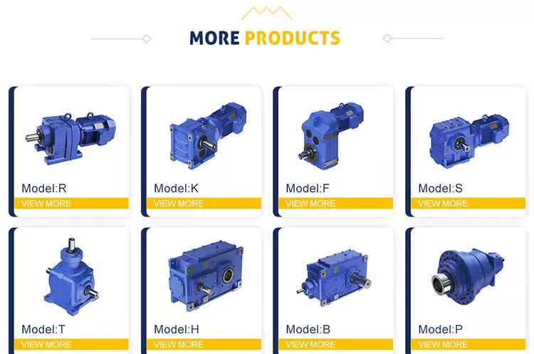
Epicyclic gearbox
An epicyclic gearbox is a type of automatic gearbox used to drive cars. Its primary advantage is its compact design, and it is more reliable and efficient than manual gearboxes. It is comprised of a sun gear and two planetary gears, encased in a ring gear called the Annulus. This system is useful for drivers who need to shift gears frequently, as they will become tired if the gears are suddenly changed.
An epicyclic gearbox consists of three different types of gears: ring gear, sun gear, and annular ring gear. The ring gear is the outermost gear and has angular-cut teeth on its inner surface. It is used in conjunction with planetary gears to provide high-speed ratios to vehicles. The sun gear also reverses the direction of the output shaft. This helps reduce transmission error.
An epicyclic gearbox uses multiple planets to transfer power between the planets. This type of gearbox is lightweight and features a high power density. This gearbox has several benefits over a standard single-stage parallel axis gearbox, including multiple load paths, unequal load sharing, and phased meshing. Furthermore, epicyclic gearboxes require more complex transmission error optimisation than their counterparts, including more than one stage.
The objective of epicyclic gearbox research is to provide the lowest transmission error possible. The process includes an initial design and detailed specification. The system is defined by its load spectrum and required ratio. Deflections of the elastic mesh are calculated to understand their strength and how much energy the system can handle. Finally, micro-geometric corrections minimize transmission error. These improvements are crucial to the overall efficiency of an epicyclic gearbox.
Extruder helical gearing
The helix in an extruder helical gearing is fixed at an angle, enabling more interaction with the shaft in the same direction as it moves. As a result, the shaft and the bearing are in constant contact for a long period of time. Typically, extruder helical gearing is used in applications where there is low excitement, such as steel, rolling mills, conveyors, and the oil industry. The bevel gear train also plays a role in these applications.
The CZPT AEX extruder drive gear is specifically developed for this specific application. The gears are compact and lightweight and offer exceptional power density and a long service life. These extruder gears are highly reliable, and they can be used in a wide range of applications, including rubber processing, food production, and recycling plants. CZPT offers both standard and custom gearing for your extruder.
Another advantage of helical gearing is its versatility. Since the helical gearing teeth are inclined at a specific angle, they can be adjusted to meet the specific needs of a given application. These gears also have the advantage of eliminating noise and shock from straight teeth. Unlike other gearing types, they are able to achieve a wide range of loads, from small to large. These helical gears are very durable and are the best option for high-load applications.
In addition to this, asymmetric helical gears have increased flexibility, while asymmetrical helical gears have lower flexural stiffness. The ratio of teeth to the shaft has a positive effect on the strength of the gear. Furthermore, asymmetrical helical gears are easier to manufacture. But before you purchase your next extruder gear, make sure you know what you’re getting into.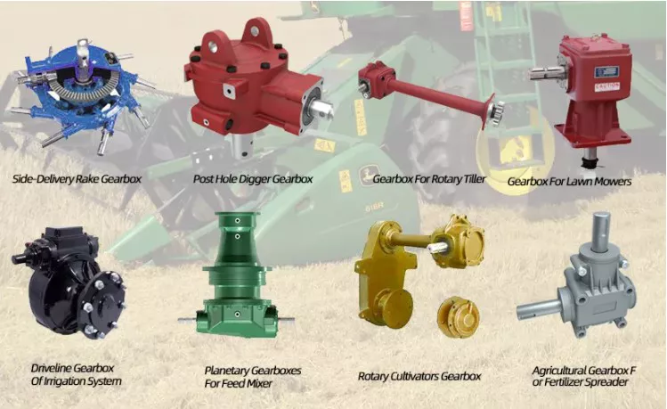
1 speed gearbox
CZPT Group Components produces the one speed gearbox. It has the potential to make cars more efficient and environmentally friendly. The gear ratio of a car’s drivetrain is crucial for reaching maximum power and speed. Typically, a one-speed gearbox delivers a maximum of 200 hp. But the speed at which a car can reach this power must be high to get the full benefit from the electric motor. So, how can a one-speed gearbox improve the speed and torque of a car?
A one-speed gearbox is a mechanical device used to switch between second and third gears. It can include multiple gear sets, such as a shared middle gear for switching between second and third gears. It can also have an intermediate gear set that represents a switchable gear in both partial transmissions. The invention also includes a mechanism that makes it easier to change gears. The patent claims are detailed below. A typical one-speed gearbox may include two parts.
Generally, a one-speed gearbox will have up to seven forward gears, with each of these corresponding to a different speed. A one-speed gearbox can have five different gear sets and five different gear levels. It can have synchronized gear sets or last-shelf gear sets. In either case, the gears are arranged in a way that maximizes their efficiency. If the gears are placed on opposite sides of a car, the transmission may be a two-speed one.
CZPT Transmission specializes in the production of high-speed gearboxes. The company’s Milltronics HBM110XT gearbox machine is the perfect tool for this job. This machine has a large working table and a heavy-duty load capacity, making it a versatile option for many kinds of applications. There are also a wide variety of CZPT gearboxes for the automotive industry.


China Custom Spur Helical Gear Box 2 Speed Reducer Power Tiller Agricultural Gearbox with Reverse with high quality
Warranty: 3 years
Applicable Industries: Building Material Shops, Manufacturing Plant, Machinery Repair Shops, Food & Beverage Factory, Farms, Home Use, Retail, Energy & Mining
Customized support: OEM, Drive Shaft Vertical Hollow Shaft Electric Motors Worm Hollow Shaft ODM, OBM, R&D
Gearing Arrangement: Bevel / Miter
Output Torque: 20~5000N.m
Input Speed: 540rpm, etc
Output Speed: 540rpm, etc
Product name: Spur Helical Gear Box Speed Reducer Power Tiller Agricultural Gearbox
Quality: 100% Test
Packing: Wooden Box
Housing Material: Iron Cating/ Almuinium
Use: Agricultural
OEM: Accepable
Keyword: Gearboxes
Certification: ISO9001:2015, ISO9001:2015
Gear Ratio: Customize
Color: Customize
Packaging Details: Standard Export Wooden Cartons of Gearbox
Item No.:
Show Room
Ratio and Shaft:
OEM acceptable
Key word
Agricultural Machinery Gearbox
Company Introduction HangZhou CZPT Machinery Co., Ltd is a factory that manufactures good & high quality Gearbox and other Agricultural machinery parts, factory wholesale Car drive shaft oem 201911 Rear Axle Shaft Driveshaft auto parts for Ferrari starting from 2571. The factory own the proficient skill with a number of patents. ProfessionalR&D office, Test laboratory, CNC lathe workshop operated by professionals. ResponsibleAttitude determines everything, details determine success or failure. We are responsible for your products. Scientific managementStrict company system and scientific material management will reduce the error rate. Our Advantages Our Services & Strength* OEM service of gearbox and other agricultural parts .* R&D service of automation equipment.* Sample testing support. * Factory visits.* Technical consultation on product selection and guidance on installation and use. FAQ Q: Are you trading company or manufacturer ?A: We are exactly a factory.Q: Do you provide samples ? is it free or extra ?A: Yes, we could offer the sample for free charge but do not pay the cost of freight.Q: How long is your delivery time ? What is your terms of payment ?A: Generally it is 40-45 days. The time may vary depending on the product and the level of customization. For standard products, In stock Fenjin MB170 marine gearbox for boat the payment is: 30% T/T in advance, balance before shippment.Q: What is the exact MOQ or price for your product ?A: As an OEM company, we can provide and adapt our products to a wide range of needs.Thus, MOQ and price may greatly vary with size, material and further specifications; For instance, costly products or standard products will usually have a lower MOQ. Please contact us with all relevant details to get the most accurate quotation.If you have another question, please feel free to contact us. Contact Us
The Different Types of Gearboxes
There are many different types of gearboxes. Some brands have more than one type. In this article, we’ll discuss the planetary gearbox, the worm reduction gearbox, the shaft mounted gearbox, and the one speed gearbox. This article will also help you determine which type of gearbox is best for your vehicle. And don’t worry if you don’t know the terminology yet. We’ll explain each type in detail so that you know what you’re getting yourself into.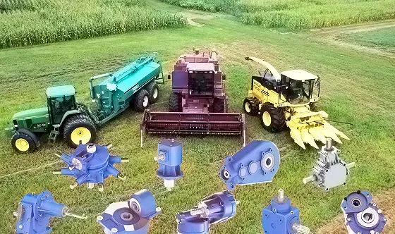
Planetary gearbox
Planetary gears have many advantages. The multiple gears in a planetary gearbox mesh simultaneously during operation. As such, they provide high efficiency and transmit high transmittable torque. These gears are widely used in various industries and are resistant to high shock loads and demanding conditions. CZPT is one of the companies that offer planetary gearboxes. Its products do not require special tools for assembly, and its scalable design minimizes safety stock.
Among the numerous benefits of planetary gearing is its compactness and lightweight. As such, it is suitable for wide applications with space and weight constraints. However, to truly appreciate its benefits, it is necessary to understand its mechanisms. Here are some of the most common details about planetary gearing:
The planetary gearbox has two mounted gears: an input shaft and an output shaft. Each gear has multiple teeth that are attached to a carrier and rotate with the input shaft. The carrier is connected to the output shaft. A planetary gear is mounted on both gears via a carrier. The carrier rotates in order to drive the planetary gear. The sun gear is often the input gear. The other gear is called the outer gear.
Planetary gearboxes are highly customizable. The size, mounting, and housing options vary, as do the reduction ratios and input speeds. Different types can be manufactured for different applications and include options such as electrical or mechanical preload. The final design of a planetary gearbox can be highly customized, based on the specifications of the application. By combining engineering excellence and ongoing innovation, planetary gearboxes provide years of trouble-free operation.
A planetary gearbox can be either an electric motor or a manual one. The latter has more features than the former, and can be used in applications where space is an issue. The primary features of a planetary gearbox include its backlash, torque, and ratio. Secondary features include noise, corrosion resistance, and construction. A planetary gearbox is a highly versatile gearbox that can drive anything from simple machinery to advanced electrical systems.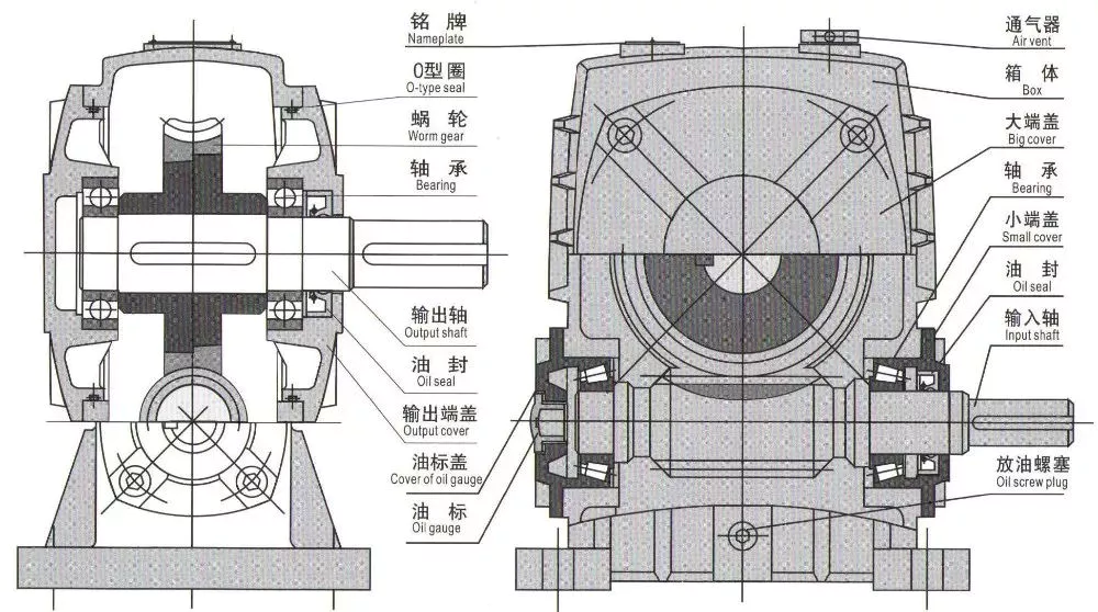
Worm reduction gearbox
The global worm reduction gearbox market report compiles key insights from the industry to help you improve your business strategy. This report will help you create a comprehensive business document that will enhance your company’s competitive edge. To obtain this report, visit our website now! Read our latest report to find out what you can expect from the global worm reduction gearbox market. Alternatively, request a sample copy for more details. Here is a sneak peek of the report:
Worm gears are made with different thread counts and are usually not matched with the CZPT standard. In general, a single thread worm should be used with a single thread worm. Worm gears have either right or left threads, and their thread count will be different as well. This type of gear is used to reduce the speed of a rotating shaft. The speed reduction ratio will be about 50 percent if the worms have the same thread count as the CZPT gears.
The standard gear set transfers power at the peak load point of a tooth, called the pitchline. The worm gear moves slowly against the wheel’s metal surface. The worm gear is also more complex than the standard gear because the worm is sliding rather than rolling. Worm gears are hard to lubricate. Moreover, the sliding contact between the gear and worm increases the complexity of the gear set. They can be a great solution for applications where noise is a significant factor.
The axial pitch and circular pitch of the worm are equal. The ratio of these two indices determines the speed of transmission. For a worm reduction gearbox to work, the axial pitch and the circular pitch must match. The pitch angle of a worm can either be left-handed or right-handed. The lead of a worm is the distance one thread travels in one revolution. The lead angle is the angle tangent to the thread helix of the cylinder’s pitch. When a worm mesh is reversed, the majority of the mesh will be on the receding arc.
Worm gears generate more heat than their counterparts, so it is important to choose a worm reduction gearbox carefully. You will want to choose the material and amount of lubricating oil carefully. Worm gears are generally made of tin bronze. The paired worms are hardened to HRC45-55. In general, they are durable, lasting up to ten years. But they will wear out – and they wear out – so you may want to consider some other factors.
Shaft-mounted gearbox
Shaft-mounted gearboxes are designed for a variety of mining and quarry applications. Their high reliability and low maintenance make them an excellent choice in these types of applications. Shaft-mounted gearboxes also feature an optional backstop device that prevents the unit from rotating in one direction. This makes them an excellent choice for applications where alignment accuracy is an issue. Here are some of the benefits of using a shaft-mounted gearbox:
Shaft-mounted gearboxes are typically constructed of aluminium, and come in sizes ranging from 050 to 125. They feature a variety of reduction ratios and ensure optimum efficiency in all operating conditions. New S series sizes, 140 and 150, extend the application range of shaft-mounted gearmotors. They are both backed by a two-year warranty. For even greater peace of mind, Shaft-mounted gearboxes are available with a range of warranty options.
The most common applications for a Shaft-mounted gearbox include traction-driven applications where a low-speed shaft is required for operation. They also are suitable for applications without a foundation, where the motor is mounted next to the reducer. To prevent the gear drive from rotating, a torque arm is attached between the motor and the shaft. Small-sized shaft-mounted gear drives are usually made without motor mount kits, which can make them an excellent choice for conveying light loads.
Another important feature of a Shaft-mounted gearbox is its mounting position. The reduced motion through the drive is redirected through the shaft, creating additional forces. These additional forces can affect the performance of the gearbox, causing vibrations and noise. Consequently, it is important to replace worn or damaged belts on a regular basis. Further, shaft-mounted gearboxes can be affected by problems with other components and amplify vibrations.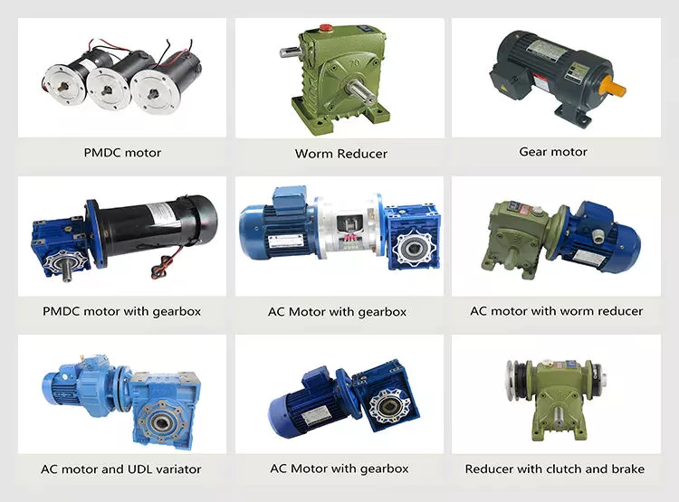
1 speed gearbox
CZPT Group Components produces one speed gearboxes. These transmissions are produced in the CZPT Group’s Kassel plant. They are compact and robust, and are designed for easy integration. The Bosch Rexroth GD1 one-speed gearbox is easy to install horizontally or vertically. The Plug and Drive system integrates the gearbox with the existing cooling system. There are many other benefits to this gearbox.
With an ID.3 electric drive motor, the maximum torque is delivered at 16,000 rpm. This single-speed transmission offers high power density and excellent noise-reduction, making it ideal for electric vehicles. The e-drive motor is extremely quiet and requires precision manufacturing. The e-drive motor also enables a wide range of driving conditions. It can reverse when needed, and reaches its maximum speed at 16,000.
The single-speed gearbox is a standard feature on most electric vehicles. Some electric vehicles, such as the Porsche Taycan, will be equipped with a two-speed gearbox. This gearbox offers more top speed and range, but it is more complex than a standard single-speed gearbox. CZPT doesn’t need to add complexity to its electric vehicles. After all, a 355 horsepower family wagon is not likely to need a dual-speed gearbox.
In addition to simplifying the transmission, the patent claims also address improvements in structural design. Fig. 5 shows a schematic representation of a transmission 50′, wherein gear sets Z1 and Z4 are exchanged between partial transmissions. This switch matrix also reflects the synchronized gears and lastshelf gears. Hydraulically betatigte Lamellenkupplungen (HBA) also form a last-shelf gear.
Another advantage of the patent claim is that it offers numerous functional freedoms, which is especially valuable in the design of an automobile. One of the patent claims identifies a tosatzlicher middle gear that allows a driver to switch between second and third gears, with a single gearbox. In a conventional one-speed transmission, the tosatzlicher middle gear is attached to the second and first part gearbox. The latter has a second and third gear.


China Standard K series Reliable quality Helical-Bevel Geared Motor Helical Gear box speed reducers with hollow shaft with Great quality
Warranty: 1YEAR
Applicable Industries: Building Material Shops, Manufacturing Plant, Machinery Repair Shops, Construction works , Energy & Mining
Gearing Arrangement: Helical
Output Torque: 14-62800N.m
Input Speed: 1400r/min
Output Speed: 0.08-261r/min
Transmission type: Helical
Output torque: 14-62800N.m
Input speed: 1400r/min
Output speed: 0.08-261r/min
Transmission ration: 5.36-17550
Permitted overhung load: 2350-190000N
Packaging Details: PACKING: CARTONS
Port: NingBo
Transmission type
Helical
Output torque
14-62800N.m
Input speed
1400r/min
Output speed
0.08-261r/min
Transmission ration
5.36-17550
Permitted overhung load
2350-190000N
Product Show
Model specification
Company Information
Packaging & Shipping
FAQQ1: Wonder if you accept small orders? A1: Do not worry. Feel free to contact us .in order to get more orders and give our clients more convener ,we accept small order.
Q2: Can you send products to my country? A2: Sure, 12mm – 32mm Wholesales Price Stainless Steel Chain Link Steel Marine Mooring Stud Link Anchor Link Chain we can. If you do not have your own ship forwarder, we can help you.
Q3: Can you do OEM for me? A3: We accept all OEM orders,just contact us and give me your design.we will offer you a reasonable price and make samples for you ASAP.
Q4: What’s your payment terms ? A4: By T/T,LC AT SIGHT,30% deposit in advance, balance 70% before shipment.
Q5: How can I place the order? A5: First sign the PI,pay deposit, High quality excellent parallel shaft gearbox then we will arrange the production.After finished production need you pay balance. Finally we will ship the Goods.
Q6: What information shall we give before placing a purchase order? A6: a)Type of the gearbox, ratio, input and output type, input flange, mounting position, and motor informationetc. b) Housing color. c) Purchase quantity. d) Other special requirements.
Q7:How to choose a gearbox which meets our requirement? A7:You can refer to our catalogue to choose the gearbox or we can help to choose when you provide the technical information of required output torque, output speed and motor parameter etc.
What Is a Gearbox?
There are several factors to consider when choosing a gearbox. Backlash, for example, is a consideration, as it is the angle at which the output shaft can rotate without the input shaft moving. While this isn’t necessary in applications without load reversals, it is important for precision applications involving load reversals. Examples of these applications include automation and robotics. If backlash is a concern, you may want to look at other factors, such as the number of teeth in each gear.
Function of a gearbox
A gearbox is a mechanical unit that consists of a chain or set of gears. The gears are mounted on a shaft and are supported by rolling element bearings. These devices alter the speed or torque of the machine they are used in. Gearboxes can be used for a wide variety of applications. Here are some examples of how gearboxes function. Read on to discover more about the gears that make up a gearbox.
Regardless of the type of transmission, most gearboxes are equipped with a secondary gear and a primary one. While the gear ratios are the same for both the primary and secondary transmission, the gearboxes may differ in size and efficiency. High-performance racing cars typically employ a gearbox with two green and one blue gear. Gearboxes are often mounted in the front or rear of the engine.
The primary function of a gearbox is to transfer torque from one shaft to another. The ratio of the driving gear’s teeth to the receiving member determines how much torque is transmitted. A large gear ratio will cause the main shaft to revolve at a slower speed and have a high torque compared to its counter shaft. Conversely, a low gear ratio will allow the vehicle to turn at a lower speed and produce a lower torque.
A conventional gearbox has input and output gears. The countershaft is connected to a universal shaft. The input and output gears are arranged to match the speed and torque of each other. The gear ratio determines how fast a car can go and how much torque it can generate. Most conventional transmissions use four gear ratios, with one reverse gear. Some have two shafts and three inputs. However, if the gear ratios are high, the engine will experience a loss of torque.
In the study of gearbox performance, a large amount of data has been collected. A highly ambitious segmentation process has yielded nearly 20,000 feature vectors. These results are the most detailed and comprehensive of all the available data. This research has a dual curse – the first is the large volume of data collected for the purpose of characterization, while the second is the high dimensionality. The latter is a complication that arises when the experimental gearbox is not designed to perform well.
Bzvacklash
The main function of a gearhead is to multiply a moment of force and create a mechanical advantage. However, backlash can cause a variety of issues for the system, including impaired positioning accuracy and lowered overall performance. A zero backlash gearbox can eliminate motion losses caused by backlash and improve overall system performance. Here are some common problems associated with backlash in gearheads and how to fix them. After you understand how to fix gearbox backlash, you’ll be able to design a machine that meets your requirements.
To reduce gearbox backlash, many designers try to decrease the center distance of the gears. This eliminates space for lubrication and promotes excessive tooth mesh, which leads to premature mesh failure. To minimize gearbox backlash, a gear manufacturer may separate the two parts of the gear and adjust the mesh center distance between them. To do this, rotate one gear with respect to the fixed gear, while adjusting the other gear’s effective tooth thickness.
Several manufacturing processes may introduce errors, and reducing tooth thickness will minimize this error. Gears with bevel teeth are a prime example of this. This type of gear features a small number of teeth in comparison to its mating gear. In addition to reducing tooth thickness, bevel gears also reduce backlash. While bevel gears have fewer teeth than their mating gear, all of their backlash allowance is applied to the larger gear.
A gear’s backlash can affect the efficiency of a gearbox. In an ideal gear, the backlash is zero. But if there is too much, backlash can cause damage to the gears and cause it to malfunction. Therefore, the goal of gearbox backlash is to minimize this problem. However, this may require the use of a micrometer. To determine how much gearbox backlash you need, you can use a dial gauge or feeler gauge.
If you’ve been looking for a way to reduce backlash, a gearbox’s backlash may be the answer. However, backlash is not a revolt against the manufacturer. It is an error in motion that occurs naturally in gear systems that change direction. If it is left unaccounted for, it can lead to major gear degradation and even compromise the entire system. In this article, we’ll explain how backlash affects gears and how it affects the performance of a gearbox.
Design
The design of gearboxes consists of a variety of factors, including the type of material used, power requirements, speed and reduction ratio, and the application for which the unit is intended. The process of designing a gearbox usually begins with a description of the machine or gearbox and its intended use. Other key parameters to consider during gearbox design include the size and weight of the gear, its overall gear ratio and number of reductions, as well as the lubrication methods used.
During the design process, the customer and supplier will participate in various design reviews. These include concept or initial design review, manufacturing design validation, critical design review, and final design review. The customer may also initiate the process by initiating a DFMEA. After receiving the initial design approval, the design will go through several iterations before the finalized design is frozen. In some cases, the customer will require a DFMEA of the gearbox.
The speed increaser gearboxes also require special design considerations. These gearboxes typically operate at high speeds, causing problems with gear dynamics. Furthermore, the high speeds of the unit increase frictional and drag forces. A proper design of this component should minimize the effect of these forces. To solve these problems, a gearbox should incorporate a brake system. In some cases, an external force may also increase frictional forces.
Various types of gear arrangements are used in gearboxes. The design of the teeth of the gears plays a significant role in defining the type of gear arrangement in the gearbox. Spur gear is an example of a gear arrangement, which has teeth that run parallel to the axis of rotation. These gears offer high gear ratios and are often used in multiple stages. So, it is possible to create a gearbox that meets the needs of your application.
The design of gearboxes is the most complex process in the engineering process. These complex devices are made of multiple types of gears and are mounted on shafts. They are supported by rolling element bearings and are used for a variety of applications. In general, a gearbox is used to reduce speed and torque and change direction. Gearboxes are commonly used in motor vehicles, but can also be found in pedal bicycles and fixed machines.
Manufacturers
There are several major segments in the gearbox market, including industrial, mining, and automotive. Gearbox manufacturers are required to understand the application and user industries to design a gearbox that meets their specific requirements. Basic knowledge of metallurgy is necessary. Multinational companies also provide gearbox solutions for the power generation industry, shipping industry, and automotive industries. To make their products more competitive, they need to focus on product innovation, geographical expansion, and customer retention.
The CZPT Group started as a small company in 1976. Since then, it has become a global reference in mechanical transmissions. Its production range includes gears, reduction gearboxes, and geared motors. The company was the first in Italy to achieve ISO certification, and it continues to grow into one of the world’s leading manufacturers of production gearboxes. As the industry evolves, CZPT focuses on research and development to create better products.
The agriculture industry uses gearboxes to implement a variety of processes. They are used in tractors, pumps, and agricultural machinery. The automotive industry uses gears in automobiles, but they are also found in mining and tea processing machinery. Industrial gearboxes also play an important role in feed and speed drives. The gearbox industry has a diverse portfolio of manufacturers and suppliers. Here are some examples of gearboxes:
Gearboxes are complex pieces of equipment. They must be used properly to optimize efficiency and extend their lifespan. Manufacturers employ advanced technology and strict quality control processes to ensure their products meet the highest standards. In addition to manufacturing precision and reliability, gearbox manufacturers ensure that their products are safe for use in the production of industrial machinery. They are also used in office machines and medical equipment. However, the automotive gearbox market is becoming increasingly competitive.


China Custom Fs Helical Worm Gear Reducer Gear Box with Motor with Free Design Custom
Solution Description
Product Introduction:
Worm helical geared motor is characterised by compact construction, mild weight, big torque and outstanding functionality. Prompt shipping in limited time. It is made of rib-reinforced rigid scenario and premium alloy-metal equipment which is hardened by carbon penetration and grinded exactly. Secure in working, reduced sound, massive in load, reduced in consumption, successful in transmission, reduced in temperature increase, and lengthy in service daily life. The mounting types are footing, flange, torque arm and so on. The output design are shaft, hollow shaft, the alpine and shrink disc are for selection.
Company Profile
l The biggest company and exporter of worm gear reducers in Asia.
l Established in 1976, we reworked from a county owned manufacturing facility to personal 1 in 1996. HangZhou SINO-DEUTSCH Electrical power TRANSMISSION Gear CO.,LTD is our new identify since 2001.
l We are the initial maker of reducers and gearboxes in China who was given export license because calendar year 1993.
l “Fixedstar” model gearboxes and reducers are the initial operator of CHINA Best Model and Most CZPT Trade Mark for reducers.
Initial to achieve ISO9001 and CE Certificate amid all makers of gearboxes in China.
As a specialist maker of worm gearbox and worm equipment reducers in China, we mainly make reduction gearbox,aluminum situation worm gearboxes,arc gear cylindrical worm gearboxes, worm gear reducers, in line helical gearboxes, and cyclo drive reducers, and so forth. These merchandise feature rational structure, secure performance, and reliable good quality, and so on. They are widely utilised in electricity, mining, metallurgy, building substance, chemical, meals, printing, ceramic, paper-producing, tobacco, and other industries.
We have 600 workers in our manufacturing unit, which addresses 70,000 square meters in HangZhou. We have been generating 2,five hundred models of reducers everyday because 2012. We are proudly exporting 70% of our products to a lot more than forty nations around the world all more than the word. Our customers come from Italy, Germany, United states, Canada, Spain, United kingdom, Mexico, Brazil, Argentina, Turkey, Singapore and other major industrial countries in the entire world. 30% of them are OEM created for immediate companies of other items.
We warmly welcome buyers from other areas of the entire world to go to us. Seeing is believing. We are really self-confident that right after visiting our facility, you will have confidence on our goods. We have the newest computerized equipments and skilled workers to make certain the stable quality and huge output. We have the most advanced technical and engineering team to assistance most demanding necessity on normal and OEM items.
Hunting forward to meeting you in HangZhou, China.
Gearboxes and reducers are enclosed mechanical reduction products generally utilized in present-day automated control techniques to command torque from your motors and complete other motion-connected jobs. A gearbox permits you to improve torque although reducing the pace of your key mover output shaft. The output shaft of the gearbox rotates at a slower velocity than the input shaft. This generates a mechanical edge, escalating torque. Conversely, your gearbox can be set in reverse, offering elevated shaft speed and diminished torque. Two common transmission configurations are straight and right angle. On the web types usually consist of helical or spur gears, planetary gears, cycloidal mechanisms, or harmonic turbines. Appropriate-angle patterns generally use worm or helical gear drives, however, hybrid drives are also accessible. Gearmotors mix an enclosed equipment established with an electric powered motor to improve torque and overall performance even though reducing velocity. Although added friction, inertia, or sharp load changes for limited-time period operation of the actuator can trigger problems, they offer a extended functioning life by preventing overloading. Numerous equipment ratios, speeds and torques are obtainable to help improve efficiency and minimize potential problems. Look through to locate the right gearbox and reducer for your automation task.
Planetary gearboxes are employed in various instances the place higher effectiveness and large reduction ratio are essential in a little area. That includes higher precision and substantial torque-to-volume ratio, it is best for torque boost, deceleration, precise positioning and manage of regenerative machinery. To guarantee that the picked planetary gearbox is the best match for your application, it is critical to consider parameters these kinds of as torque, backlash and equipment ratios when selecting a planetary gearbox.

in Istanbul Turkey sales price shop near me near me shop factory supplier Trc Customized Ground Foot Mounted Helical Rack Gears Helical Gear Box Micro Helical Gear Box Motor Variable Speed Gear Motor Reduction Gear Box manufacturer best Cost Custom Cheap wholesaler

Obtaining amassed treasured experience in cooperating with overseas customers, Hangzhou EPG Co.,Ltd. , was founded in November, 1997. With its five wholly owned subsidiaries. a specialised provider of a total selection of chains, sprockets, gears, gear racks, V-belts, couplings and reducers.
TRC EPT ground helical rack EPTs EPTcal EPT box EPT helical EPT box motor variable pace EPT motor reduction EPT box
EPTnical functions:
The extremely modular is a design and style functions of SRC helical EPTTes variety. It can be related respectively with motors this kind of as normal motor,brake motor,explosion-proof motor,frequency conversion motor,servo motor,IEC motor and so on. This type of merchandise is extensively utilised in EPT fields these kinds of as textile,foodstuff,EPT EPTT,EPT,plastics and so on. It is attainable to set up the variation necessary using flanges or feet
Solution attributes:
SLRC series helical EPT models has a lot more than 4 kinds,EPTT .12kw-4kw,ratio3.66-54max torque120-500NM,It can be connected(foot or flange)discretionary and use multi-mounting positions according customers’ requirements
1 Ground-hardened helical EPTs
two. Modularity,can be blended in many kinds
3. EPTT casing,ligEPTT bodyweight
four. EPTs in carbonize hard,durable
5. EPT mouting
6. Refined design, compact in structure and minimal sounds
EPTT information
EstabEPTTd in 1985, EPT EPTT EPTTRY EPTT, LTD is a substantial and new EPT EPTTrprise participating in analysis, deveXiHu (West EPT) Dis.Hu (West EPT) Dis. and manufacture for EPTT amp speed variator, 1 of the director member of EPTT EPTT Association of EPTT EPTT EPTTry.
It handles more than forty,000 square meters, has more than four hundred workers , 20% of whom are professionals, equipped with more than 300 sets the most EPTd exact numerical manage equipment, incXiHu (West EPT) Dis.Hu (West EPT) Dis. German HOFLER forming EPT grinding EPTT to enhance good quality.
established up more than thirty nationwide income branches to provide our clients in time and extensively.
Our goods also exported to much more than thirty nations around the world main in Europe, Asia The united states, and Africa, with high status.
EPTT control
EPTT
Related EPTT sorts
| EPT Planetary EPTT | Robot RV EPTT speed EPTT |
| Custom produced Non-stXiHu (West EPT) Dis.Hu (West EPT) Dis.rd EPTT | UDL Sequence Variator |
| PYZ Sequence EPTcal Tooth Shaft Mounted EPTT | 8000 Collection Cycloidal EPTT |
| SLT Sequence Spiral EPTTl EPTT | SLSWL Series Worm Screw Jack |
| SLP Sequence Planetary EPTT | SLH/SLB Sequence EPT EPTT EPTT |
| NMRV Sequence Worm EPTT | BKM Sequence EPTcal-hypoid EPTT |
| SLRC Collection EPTcal EPTT | SLEPTR Sequence Shaft Mounted EPTT |
| SLXG Series Shaft Mounted EPTT | X/B Sequence Cycloidal EPTT |
| SLR/SEPTT/SLK/SLS Series EPTcal EPTT | AC/DC EPT |
Principal item listing: 16 series incXiHu (West EPT) Dis.Hu (West EPT) Dis. SLR/SLS/SLK/SEPTT series challenging tooth flank EPT EPTT , SLRC collection aluminium circumstance helical EPT EPTTs,SLHSLB series high EPTT velocity EPTT, SLP sequence planetary speed EPTT, X/B sequence cycloidal EPTT, SLXG collection shaft-mounted EPT box, SLSWL collection worm screw jack, SLT sequence helical cone EPT box, altogether more than ten,000 ratios, a variety of specification make us at the head of domestic EPTT market, broadly provide the mechanical EPTT area of ligEPTT amp weighty industry this sort of as: beer amp EPTTrage, mining EPTT, meals EPTT, textile printing, rubber amp plastic substance, petrochemical market, jack-up transportation, pharmacy amp process hides, environmental protection tools.
Certification
FAQ
one.Payment Time period: TT, L/C
2.Shipping time: about 30 daEPTTfrom EPT payment.
three.We take EPT products as for every your EPTT prerequisite.
four.XiHu (West EPT) Dis.hu (West EPT) Dis.lines for the Choice:Normally we can choose 1 EPTT which is appropriate for you with some informations from you,this sort of as ratio/motor pace/mounting dimension/ out torque etc.
five.If the least orEPTTamount is in excess of $ten thousand, there are preferential.
Q1: What information need to I explain to you to affirm the solution?
A:Design/Dimensions, EPTT Ratio, Shaft directions amp OrEPTTquantity.
Q2: What can i do if I don’t know which one EPT?
A:Dont fear, Send as much information as you can, our group will assist you uncover the rigEPTT a single you are seeking for.
Q3: What is your solution guarantee period?
A:We offer you a single year guarantee given that the vessel departure day remaining EPTT.
Q4: Are you buying and selling business or company ?
A: We are manufacturing facility.
Q5: How EPTT is your shipping time?
A: EPTTly it is 5-ten daEPTTif the goods are in inventory. or it is 15-20 daEPTTif the items are not in stock, it is in accordance to amount.
Q6: Do you offer samples ? is it free or extra ?
A: Sure, we could offer the sample for cost-free cost but do not pay out the EPT of freight.
Q7: What is your phrases of payment ?
A: Payment lt=1000USD, 100% in EPT. Payment gt=1000USD, 30% T/T in EPT ,harmony prior to shippment.
If you have an additional issue, pls come to feel free of charge to make contact with us as underneath:
Contact Us

