Product Description
Product Description
FCNDK series reducer is a new-generation of products developed by our factory on the basis of introducing foreign advanced technology,its’ main features are as follows:
1 Made of high quality aluminum alloy, light weight and non-rusting
2 Large output torque and high radiating efficiency
3 Smooth running and low noise
4 Good-looking appearance, durable service life and small volume
5 Suitable for omnibearing installation
|
|
|
|||||||||||||||||||||||||||||||||||||||||||||||||||||||||||||||||||||||||||||||||||||||||||||||||||||||||||||||||||||||||||||||||||||||||||||||||||||||||||||||||||||||||||||||||||||||||||||||||||||||||||||||||||||||||||||||||||||||||||||||||||||||||||||||||||||||||||||||||||||||||||||||||||||||||||||||||||||||||||||||||||||||||||||||||||||||||||||||||||||||||||||||||||||||||||||||||||||||||||||||||||||||||||||||||||||||||||||||||||||||||||||||||||||||||||||||||||||||||||||||||||||||||||||||||||||||||||||||||||||||||||||||||||||
Our factory is the main manufacturer and exporter of worm gear reducer in China. We were founded in 1976. We are the best seller in export of worm gears in China, 1st to achieve export License and 1st to achieve ISO9001 and CE Certificate among manufacturers of reducers in China. We are private enterprises since 1996. We have workers and employees of 500 and the yearly output last year is 25 million U. S. Dollars. About 70% of the total output is exported to as many as 38 countries such as USA, Canada, Italy, Spain, , Germany, UK, Japan, Korea, Indonesia, and etc.
Company Profile
Formerly known as HangZhou Reducer Factory, CHINAMFG Group was founded in 1976.
Presently, our commitment extends beyond manufacturing as we engage in diligent research and trading endeavors. Our primary focus centers on power transmission products, constituting the core of our business operations.
Having invested a total of 2 billion Yuan in land spHangZhou an impressive 200,000 square meters, our workforce of 1000 dedicated employees now produce over 3,500 distinct types of gearboxes each day, serving the global market.
With unwavering commitment to research and development over a span of 45 years, CHINAMFG takes great pride in holding the esteemed distinction of being the largest manufacturer of small and medium-sized speed reducers in Asia.
Our main products range from Worm Gear Reducers, Helical Gear Reducers, Helical Bevel Reducers, Shaft Mounted Reducers to Slewing drives and more.
As a professional manufacturer of worm gearbox and worm gear reducers in China, we mainly produce reduction gearbox,aluminum case worm gearboxes,arc gear cylindrical worm gearboxes, worm gear reducers, in line helical gearboxes, and cyclo drive reducers, etc. These products feature rational structure, stable performance, and reliable quality, and so on. They are widely used in power, mining, metallurgy, building material, chemical, food, printing, ceramic, paper-making, tobacco, and other industries.
We have 600 workers in our factory, which covers 70,000 square CHINAMFG in HangZhou. We have been making 2,500 units of reducers everyday since 2012. We are proudly exporting 70% of our products to more than 40 countries all over the word. Our customers come from Italy, Germany, USA, Canada, Spain, UK, Mexico, Brazil, Argentina, Turkey, Singapore and other main industrial countries in the world. 30% of them are OEM made for direct manufacturers of other products.
We warmly welcome customers from other parts of the world to visit us. Seeing is believing. We are very confident that after visiting our facility, you will have confidence on our products. We have the latest automatic equipments and experienced workers to ensure the stable quality and large output. We have the most sophisticated technical and engineering team to support most demanding requirement on standard and OEM products.
Looking CHINAMFG to meeting you in HangZhou, China.
/* January 22, 2571 19:08:37 */!function(){function s(e,r){var a,o={};try{e&&e.split(“,”).forEach(function(e,t){e&&(a=e.match(/(.*?):(.*)$/))&&1
| Application: | Motor, Machinery, Marine, Agricultural Machinery, Industry |
|---|---|
| Function: | Distribution Power, Change Drive Torque, Change Drive Direction, Speed Changing, Speed Reduction |
| Layout: | Vertical |
| Hardness: | Hardened Tooth Surface |
| Installation: | Vertical Type |
| Step: | Single-Step |
| Samples: |
US$ 22/Piece
1 Piece(Min.Order) | |
|---|
| Customization: |
Available
| Customized Request |
|---|
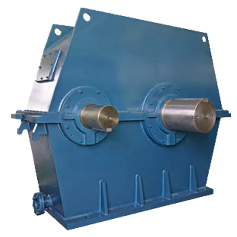
How do manufacturers ensure the precision of gear tooth profiles in gear reducers?
Manufacturers employ several techniques to ensure the precision of gear tooth profiles in gear reducers, which is crucial for optimal performance and efficiency:
1. Precision Machining: Gear teeth are typically machined using advanced CNC (Computer Numerical Control) machines that can achieve high levels of accuracy and repeatability. This ensures consistent gear tooth profiles across multiple components.
2. Quality Control Measures: Rigorous quality control processes, such as dimensional inspections and profile measurements, are performed at various stages of manufacturing to verify that gear tooth profiles meet the required specifications.
3. Tooth Profile Design: Engineers use specialized software and simulation tools to design gear tooth profiles with precise involute shapes and accurate dimensions. These designs are then translated into machine instructions for manufacturing.
4. Material Selection: High-quality materials with excellent wear resistance and dimensional stability are chosen to minimize the potential for deformation or inaccuracies during machining and operation.
5. Heat Treatment: Heat treatment processes, such as carburizing and quenching, are applied to enhance the surface hardness and durability of gear teeth, reducing the risk of wear and deformation over time.
6. Tooth Grinding and Finishing: After initial machining, gear teeth often undergo precision grinding and finishing processes to achieve the desired tooth profile accuracy and surface finish.
7. Post-Processing Inspection: Gear tooth profiles are inspected again after manufacturing processes to verify that the final components meet the specified tolerances and performance criteria.
8. Computer-Aided Manufacturing (CAM): CAM software is used to generate tool paths and machining instructions, enabling precise control over tool movements and material removal during gear manufacturing.
By combining these techniques and leveraging advanced manufacturing technologies, manufacturers can achieve the necessary precision in gear tooth profiles, resulting in reliable and efficient gear reducers for various industrial applications.
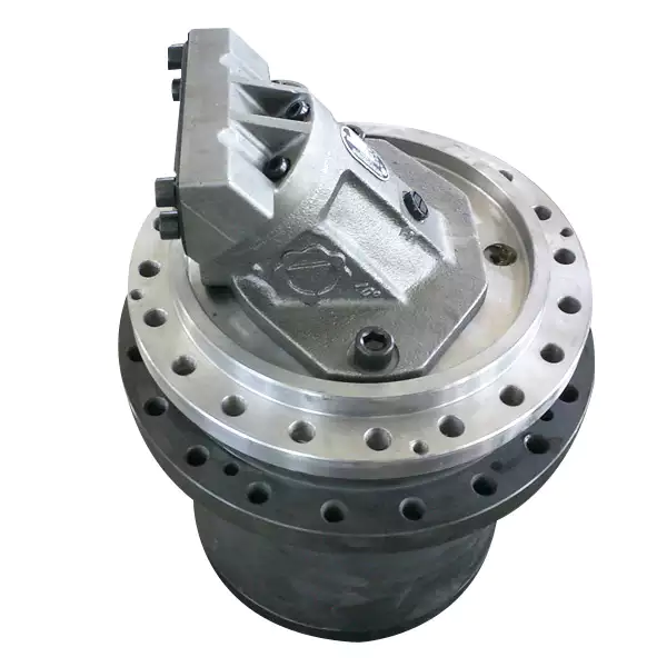
What factors should be considered when selecting the right gear reducer?
Choosing the appropriate gear reducer involves considering several crucial factors to ensure optimal performance and efficiency for your specific application:
- 1. Torque and Power Requirements: Determine the amount of torque and power your machinery needs for its operation.
- 2. Speed Ratio: Calculate the required speed reduction or increase to match the input and output speeds.
- 3. Gear Type: Select the appropriate gear type (helical, bevel, worm, planetary, etc.) based on your application’s torque, precision, and efficiency requirements.
- 4. Mounting Options: Consider the available space and the mounting configuration that suits your machinery.
- 5. Environmental Conditions: Evaluate factors such as temperature, humidity, dust, and corrosive elements that may impact the gear reducer’s performance.
- 6. Efficiency: Assess the gear reducer’s efficiency to minimize power losses and improve overall system performance.
- 7. Backlash: Consider the acceptable level of backlash or play between gear teeth, which can affect precision.
- 8. Maintenance Requirements: Determine the maintenance intervals and procedures necessary for reliable operation.
- 9. Noise and Vibration: Evaluate noise and vibration levels to ensure they meet your machinery’s requirements.
- 10. Cost: Compare the initial cost and long-term value of different gear reducer options.
By carefully assessing these factors and consulting with gear reducer manufacturers, engineers and industry professionals can make informed decisions to select the right gear reducer for their specific application, optimizing performance, longevity, and cost-effectiveness.
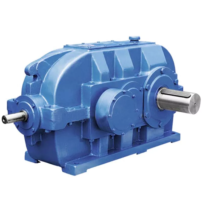
How do gear reducers handle variations in input and output speeds?
Gear reducers are designed to handle variations in input and output speeds through the use of different gear ratios and configurations. They achieve this by utilizing intermeshing gears of varying sizes to transmit torque and control rotational speed.
The basic principle involves connecting two or more gears with different numbers of teeth. When a larger gear (driving gear) engages with a smaller gear (driven gear), the rotational speed of the driven gear decreases while the torque increases. This reduction in speed and increase in torque enable gear reducers to efficiently adapt to variations in input and output speeds.
The gear ratio is a critical factor in determining how much the speed and torque change. It is calculated by dividing the number of teeth on the driven gear by the number of teeth on the driving gear. A higher gear ratio results in a greater reduction in speed and a proportionate increase in torque.
Planetary gear reducers, a common type, use a combination of gears including sun gears, planet gears, and ring gears to achieve different speed reductions and torque enhancements. This design provides versatility in handling variations in speed and torque requirements.
In summary, gear reducers handle variations in input and output speeds by using specific gear ratios and gear arrangements that enable them to efficiently transmit power and control motion characteristics according to the application’s needs.


editor by CX 2024-05-15
China supplier Worm Screw Gearbox Worm Gear Reducer Water Recycling Systems Speed Reduction gearbox drive shaft
Product Description
Detailed Images
Detailed Images of Worm Gear Reducer NMRV 130 150
Fixedstar Upgraded Gear Reducer Models
Product Description
Specifications of Worm Gear Reducer NMRV 130 150
|
item |
Worm Gear Reducer Worm Gearbox |
|
Warranty |
1 Year |
|
Applicable Industries |
Manufacturing Plant, Food & Beverage Factory, Farms, Construction works , Energy & Mining, Other |
|
Weight (KG) |
6.2 |
|
Customized support |
OEM |
|
Place of CHINAMFG |
China |
|
|
ZHangZhoug |
|
Brand Name |
CHINAMFG |
|
Gearing Arrangement |
Worm |
|
Output Torque |
2.6-1650Nm |
|
Input Speed |
1400rpm |
|
Output Speed |
0.5-186.7rpm |
|
Product name |
Worm Gear Reducer Worm Gearbox |
|
Size |
130 150 |
|
Ratio |
5/7.5/10/15/20/25/30/40/50/60/80/100 |
|
Worm Wheel Material |
12-2 Tin Bronze |
|
Worm Shaft Material |
20CrMnTi |
|
Bearing |
C&U |
|
Oil Seal |
CHINAMFG CHINAMFG |
|
Lubricant Oil |
Synthetic Oil |
|
Color |
Blue(RAL5571)/Silver Grey (RAL9571)/Custom-Made |
Description of Worm Gear Reducer NMRV 130 150
Made of high-quality aluminium alloy, light weight and non-rusting.
The reducer model from 25 to 90 are made of aluminum alloy die-casting material, model 110-150 are made of cast iron. It’s good looking in appearance, compact in structure, rust proofing on surface and small volume to save mounting space.
Large output torque and high radiating efficiency, the strong capacity of loading ensure stable transmission, make less vibration and noise.
Suitable for omnibearing installation, varies of connecting structure for different requirements.
*Inch sizes reducer are available.
FCN worm gearbox reducer is a commodity with sophistcated design and continous improvements, its main features are made of high quality alumium alloy, light weight and non-rusting, larget output toque, smooth running and low noise, high radiating efficiency, good looking apprearance, derable service life, small volume and suitable for all mouting positions.
Drawings of Worm Gear Reducer NMRV 130 150
Packing & Delivery
Packaging Pictures of Worm Gear Reduce and Helical Geared Motor
Inner Packing: PP bag with carton;
Outer Packing: Carton boxes and wooden cases;
Leadtime: 20-30 days CHINAMFG order confirm.
About Us
Welcome to CHINAMFG Group, China’s leading gearbox manufacturer since 1976. Our journey, spHangZhou over 4 decades, has established us as a benchmark of CHINAMFG in the power transmission industry.
We proudly made history in the 1980s by exporting the first China-made reducer and have since maintained our status as China’s top gearbox exporter.Today, we proudly export 70% of our products to more than 40 countries, including key markets like Italy, Germany, the USA, Spain, Brazil, Argentina, Turkey, and India.
Our extensive product range includes worm gear reducers, helical gearboxes, shaft-mounted reducers, helical bevel gearboxes, and slewing drives.These products are vital across various sectors, from industrial production equipment, power, and mining to metallurgy, agriculture, construction, and marine, as well as in the burgeoning clean energy sector.
Our team of experts, among the world’s best, upholds the highest standards for both standard and OEM products. Driven by innovation and cutting-edge technology, we prioritize quality and our customers’ needs. Our state-of-the-art facilities, equipped with the latest machinery and a team of seasoned professionals, ensure consistent quality and impressive daily output. We’re proud to produce 4,000 units daily, totaling over 1.2 million units annually.
We cordially invite you to visit us and witness first hand why CHINAMFG Group is the gem of China’s gearbox manufacturing. Seeing is believing, and we eagerly anticipate demonstrating our expertise and craftsmanship. Join us in driving the future forward.
/* January 22, 2571 19:08:37 */!function(){function s(e,r){var a,o={};try{e&&e.split(“,”).forEach(function(e,t){e&&(a=e.match(/(.*?):(.*)$/))&&1
| Hardness: | Hardened Tooth Surface |
|---|---|
| Installation: | Horizontal Type |
| Layout: | Vertical |
| Gear Shape: | Bevel Gear |
| Step: | Single-Step |
| Type: | Worm Reducer |
| Customization: |
Available
| Customized Request |
|---|
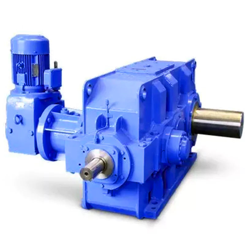
What are the considerations for choosing the appropriate lubrication for gear reducers?
Choosing the appropriate lubrication for gear reducers is crucial for ensuring optimal performance, longevity, and efficiency. Several considerations should be taken into account when selecting the right lubrication:
1. Load and Torque: The magnitude of the load and torque transmitted by the gear reducer affects the lubrication’s viscosity and film strength requirements. Heavier loads may necessitate higher viscosity lubricants.
2. Operating Speed: The speed at which the gear reducer operates impacts the lubrication’s ability to maintain a consistent and protective film between gear surfaces.
3. Temperature Range: Consider the temperature range of the operating environment. Lubricants with suitable viscosity indexes are crucial to maintaining performance under varying temperature conditions.
4. Contaminant Exposure: If the gear reducer is exposed to dust, dirt, water, or other contaminants, the lubrication should have proper sealing properties and resistance to contamination.
5. Lubrication Interval: Determine the desired maintenance interval. Some lubricants require more frequent replacement, while others offer extended operational periods.
6. Compatibility with Materials: Ensure that the chosen lubricant is compatible with the materials used in the gear reducer, including gears, bearings, and seals.
7. Noise and Vibration: Some lubricants have properties that can help reduce noise and dampen vibrations, improving the overall user experience.
8. Environmental Impact: Consider environmental regulations and sustainability goals when selecting lubricants.
9. Manufacturer Recommendations: Follow the manufacturer’s recommendations and guidelines for lubrication type, viscosity grade, and maintenance intervals.
10. Monitoring and Analysis: Implement a lubrication monitoring and analysis program to assess lubricant condition and performance over time.
By carefully evaluating these considerations and consulting with lubrication experts, industries can choose the most suitable lubrication for their gear reducers, ensuring reliable and efficient operation.
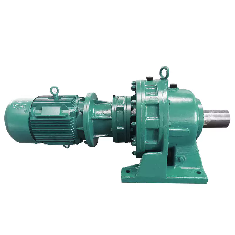
What role do gear ratios play in optimizing the performance of gear reducers?
Gear ratios play a crucial role in optimizing the performance of gear reducers by determining the relationship between input and output speeds and torques. A gear ratio is the ratio of the number of teeth between two meshing gears, and it directly influences the mechanical advantage and efficiency of the gear reducer.
1. Speed and Torque Conversion: Gear ratios allow gear reducers to convert rotational speed and torque according to the needs of a specific application. By selecting appropriate gear ratios, gear reducers can either reduce speed while increasing torque (speed reduction) or increase speed while decreasing torque (speed increase).
2. Mechanical Advantage: Gear reducers leverage gear ratios to provide mechanical advantage. In speed reduction configurations, a higher gear ratio results in a greater mechanical advantage, allowing the output shaft to deliver higher torque at a lower speed. This is beneficial for applications requiring increased force or torque, such as heavy machinery or conveyor systems.
3. Efficiency: Optimal gear ratios contribute to higher efficiency in gear reducers. By distributing the load across multiple gear teeth, gear reducers with suitable gear ratios minimize stress and wear on individual gear teeth, leading to improved overall efficiency and prolonged lifespan.
4. Speed Matching: Gear ratios enable gear reducers to match the rotational speeds of input and output shafts. This is crucial in applications where precise speed synchronization is required, such as in conveyors, robotics, and manufacturing processes.
When selecting gear ratios for a gear reducer, it’s important to consider the specific requirements of the application, including desired speed, torque, efficiency, and mechanical advantage. Properly chosen gear ratios enhance the overall performance and reliability of gear reducers in a wide range of industrial and mechanical systems.
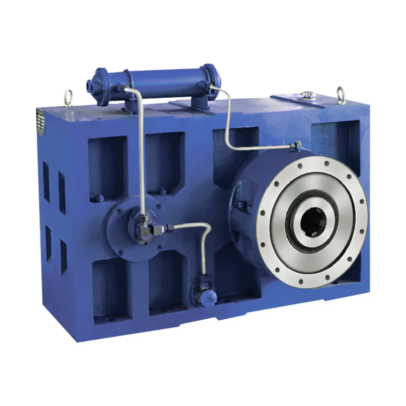
What industries and machinery commonly utilize gear reducers?
Gear reducers are widely used across various industries and types of machinery for torque reduction and speed control. Some common industries and applications include:
- 1. Manufacturing: Gear reducers are used in manufacturing equipment such as conveyors, mixers, and packaging machines to control speed and transmit power efficiently.
- 2. Automotive: They are utilized in vehicles for applications like power transmission in transmissions and differentials.
- 3. Aerospace: Gear reducers are used in aircraft systems, including landing gear mechanisms and engine accessories.
- 4. Robotics and Automation: They play a crucial role in robotic arms, CNC machines, and automated production lines.
- 5. Mining and Construction: Gear reducers are used in heavy machinery like excavators, bulldozers, and crushers for power transmission and torque multiplication.
- 6. Energy and Power Generation: Wind turbines, hydroelectric generators, and other power generation equipment use gear reducers to convert rotational speed and transmit power.
- 7. Marine and Shipbuilding: They are used in ship propulsion systems, steering mechanisms, and anchor handling equipment.
- 8. Material Handling: Gear reducers are essential in conveyor systems, elevators, and hoists for controlled movement of materials.
- 9. Food and Beverage: They find applications in food processing equipment like mixers, grinders, and packaging machines.
- 10. Paper and Pulp: Gear reducers are used in machinery for pulp processing, paper production, and printing.
These examples represent just a fraction of the industries and machinery that benefit from the use of gear reducers to optimize power transmission and achieve the desired motion characteristics.


editor by CX 2024-05-14
China Professional Helical Hypoid Gear Reducer Price Mini Bevel Gearbox Worm Drive Shaft Gear Box Zero Backlash Worm Reducer Zero Backlash Worm with Great quality
Product Description
Detailed Photos
Features of S series reducer
The same model can be equipped with motors of various powers. It is easy to realize the combination and connection between various models.
The transmission efficiency is high, and the single reducer efficiency is up to 96%. three
The transmission ratio is subdivided and the range is wide. The combined model can form a large transmission ratio and low output speed.
The installation forms are various, and can be installed with any foot, B5 flange or B4 flange. The foot mounting reducer has 2 machined foot mounting planes.
Helical gear and worm gear combination, compact structure, large reduction ratio.
Installation mode: foot installation, hollow shaft installation, flange installation, torque arm installation, small flange installation.
Input mode: motor direct connection, motor belt connection or input shaft, connection flange input.
Average efficiency: reduction ratio 7.5-69.39 is 77%; 70.43-288 is 62%; The S/R combination is 57%.
S57 SF57 SA57 SAF57 S series helical worm gear box speed reducer 0.18kw 0.25kw 0.37kw 0.55kw 0.75kw 1.1kw 1.5kw 2.2kw 3kw, max. permissible torque up to 300Nm, transmission ratios from 10.78 to 196.21. Mounting mode: foot mounted, flange mounted, short flange mounted, torque arm mounted. Output shaft: CHINAMFG shaft, hollow shaft (with key, with shrink disc and with involute spline).
Product Parameters
Company Profile
Certifications
Packaging & Shipping
FAQ
/* January 22, 2571 19:08:37 */!function(){function s(e,r){var a,o={};try{e&&e.split(“,”).forEach(function(e,t){e&&(a=e.match(/(.*?):(.*)$/))&&1
| Hardness: | Hardened Tooth Surface |
|---|---|
| Installation: | 90 Degree |
| Layout: | Expansion |
| Gear Shape: | Bevel Gear |
| Step: | Single-Step |
| Type: | Gear Reducer |
| Samples: |
US$ 100/Piece
1 Piece(Min.Order) | |
|---|

How do manufacturers ensure the precision of gear tooth profiles in gear reducers?
Manufacturers employ several techniques to ensure the precision of gear tooth profiles in gear reducers, which is crucial for optimal performance and efficiency:
1. Precision Machining: Gear teeth are typically machined using advanced CNC (Computer Numerical Control) machines that can achieve high levels of accuracy and repeatability. This ensures consistent gear tooth profiles across multiple components.
2. Quality Control Measures: Rigorous quality control processes, such as dimensional inspections and profile measurements, are performed at various stages of manufacturing to verify that gear tooth profiles meet the required specifications.
3. Tooth Profile Design: Engineers use specialized software and simulation tools to design gear tooth profiles with precise involute shapes and accurate dimensions. These designs are then translated into machine instructions for manufacturing.
4. Material Selection: High-quality materials with excellent wear resistance and dimensional stability are chosen to minimize the potential for deformation or inaccuracies during machining and operation.
5. Heat Treatment: Heat treatment processes, such as carburizing and quenching, are applied to enhance the surface hardness and durability of gear teeth, reducing the risk of wear and deformation over time.
6. Tooth Grinding and Finishing: After initial machining, gear teeth often undergo precision grinding and finishing processes to achieve the desired tooth profile accuracy and surface finish.
7. Post-Processing Inspection: Gear tooth profiles are inspected again after manufacturing processes to verify that the final components meet the specified tolerances and performance criteria.
8. Computer-Aided Manufacturing (CAM): CAM software is used to generate tool paths and machining instructions, enabling precise control over tool movements and material removal during gear manufacturing.
By combining these techniques and leveraging advanced manufacturing technologies, manufacturers can achieve the necessary precision in gear tooth profiles, resulting in reliable and efficient gear reducers for various industrial applications.
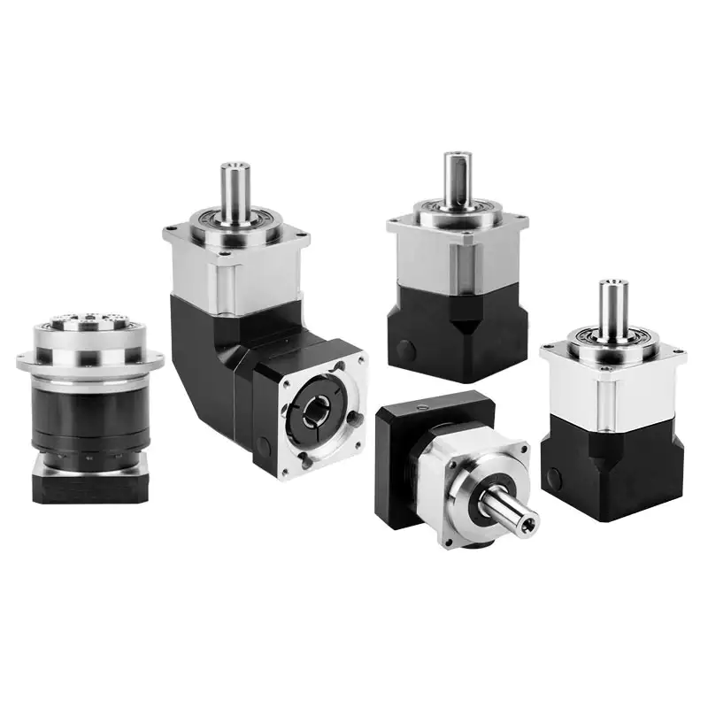
Can gear reducers be used for both speed reduction and speed increase?
Yes, gear reducers can be utilized for both speed reduction and speed increase, depending on their design and arrangement. The functionality to either decrease or increase rotational speed is achieved by altering the arrangement of gears within the gearbox.
1. Speed Reduction: In speed reduction applications, a gear reducer is designed with gears of different sizes. The input shaft connects to a larger gear, while the output shaft is connected to a smaller gear. As the input shaft rotates, the larger gear turns the smaller gear, resulting in a decrease in output speed compared to the input speed. This configuration provides higher torque output at a lower speed, making it suitable for applications that require increased force or torque.
2. Speed Increase: For speed increase, the gear arrangement is reversed. The input shaft connects to a smaller gear, while the output shaft is connected to a larger gear. As the input shaft rotates, the smaller gear drives the larger gear, resulting in an increase in output speed compared to the input speed. However, the torque output is lower than that of speed reduction configurations.
By choosing the appropriate gear ratios and arrangement, gear reducers can be customized to meet specific speed and torque requirements for various industrial applications. It’s important to select the right type of gear reducer and configure it correctly to achieve the desired speed reduction or speed increase.
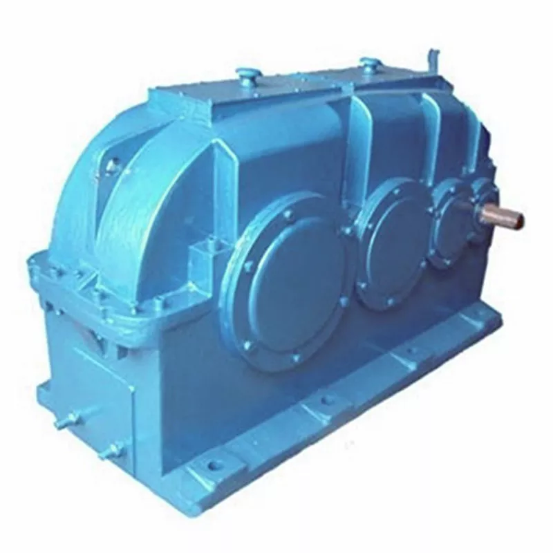
How do gear reducers contribute to speed reduction and torque increase?
Gear reducers play a crucial role in mechanical systems by achieving speed reduction and torque increase through the principle of gear ratios. Here’s how they work:
Gear reducers consist of multiple gears with different sizes, known as gear pairs. These gears are meshed together, and their teeth interlock to transmit motion and power. The gear ratio is determined by the ratio of the number of teeth on the input gear (driver) to the number of teeth on the output gear (driven).
Speed Reduction: When a larger gear (output gear) is driven by a smaller gear (input gear), the output gear rotates at a slower speed than the input gear. This reduction in speed is proportional to the gear ratio. As a result, gear reducers are used to slow down the rotational speed of the output shaft compared to the input shaft.
Torque Increase: The interlocking teeth of gears create a mechanical advantage that allows gear reducers to increase torque output. When the input gear applies a force (torque) to the teeth, it is transmitted to the output gear with greater force due to the leverage provided by the larger diameter of the output gear. The torque increase is inversely proportional to the gear ratio and is essential for applications requiring high torque at lower speeds.
By selecting appropriate gear ratios and arranging gear pairs, gear reducers can achieve various speed reduction and torque multiplication factors, making them essential components in machinery and equipment where precise control of speed and torque is necessary.


editor by CX 2024-05-09
China Professional Truck Crane Tow Truck Wrecker Slew Drive Worm Speed Reducer Hydraulic Slewing Gearbox Planetary Gear Motor Reducer sequential gearbox
Product Description
Product Description
CHINAMFG planetary reducer gearbox is designed with large torque, high start and transmission efficiency, low-speed stability,compact radial size, low noise, etc. The main devices we are making are walking reducers, lifting reducers and swing reducers.
They are widely used for vehicle cranes, crawler cranes, truck mounted cranes, marine cranes, aerial work trucks, excavators, etc.
1)Compact size
2)Low noise
3)High transmission efficiency
4)Good working condition under lower speed
5)Customized hydraulic motors
and brakes for different request
6)One Year Warranty from reception 7)Free components for replacement within warranty period
8)Professional and tailored solution for different requirements
9)Free technical support at any time
10)Customer training isavailable.
Product Parameters
|
Slewing Reducer
|
||||
|
Model
|
DH12B20E
|
DH17B32E
|
DH18B39S
|
DH25B32S
|
|
Max. output torque
|
12000 Nm
|
16500 Nm
|
17500 Nm
|
25000 Nm
|
|
Ratio
|
20.9
|
31.36
|
38.82
|
31.36
|
|
Weight (no motor, oil, drum)
|
125 kgs
|
165 kgs
|
225 kgs
|
240 kgs
|
|
Modules of output gear; Modification Coefficient
|
m=8,10,12,14mm; x=0.5
|
m=8,10,12,14mm; x=0.5
|
m=8,10,12,14mm; x=0.5
|
m=12,14,16mm; x=0.5
|
|
Model
|
DH29B40S
|
DH29B60S
|
DH38B100S
|
DH50B120S
|
|
Max. output torque
|
28500 Nm
|
29000 Nm
|
38000 Nm
|
48500 Nm
|
|
Ratio
|
39.43
|
60.13
|
100.75
|
120.83
|
|
Weight (no motor, oil, drum)
|
210-260 kgs
|
250 kgs
|
315 kgs
|
380-425 kgs
|
|
Modules of output gear; Modification Coefficient
|
m=12,14,16mm; x=0.5
|
m=12,14,16mm; x=0.5
|
m=12,14,16mm; x=0.5
|
m=16 or 18mm; x=0.5
|
|
Hydraulic motor
|
Motor interface structure can be designed with customer requirement
|
|||
|
Remark
|
1. The input steering direction is opposite to the output. 2. For more ratio requirements, please consult us.
|
|||
Packaging & Shipping
1. Packed by wooden box, fumigation-free for export and import standard.
2. Shipped by sea or air with customer require
Company Profile
FAQ
/* January 22, 2571 19:08:37 */!function(){function s(e,r){var a,o={};try{e&&e.split(“,”).forEach(function(e,t){e&&(a=e.match(/(.*?):(.*)$/))&&1
| Application: | Electric Cars, Machinery, Marine, Car, Lift Equipment |
|---|---|
| Hardness: | Hardened Tooth Surface |
| Installation: | Vertical Type |
| Layout: | Coaxial |
| Step: | Four-Step |
| Ratio: | Customized |
| Customization: |
Available
| Customized Request |
|---|

How do gear reducers enhance the efficiency of conveyor systems and robotics?
Gear reducers play a significant role in improving the efficiency of both conveyor systems and robotics by optimizing speed, torque, and control. Here’s how they contribute:
Conveyor Systems:
In conveyor systems, gear reducers enhance efficiency in the following ways:
- Speed Control: Gear reducers allow precise control over the rotational speed of conveyor belts, ensuring that materials are transported at the desired speed for efficient production processes.
- Torque Adjustment: By adjusting gear ratios, gear reducers provide the necessary torque to handle varying loads and prevent overloading, minimizing energy wastage.
- Reverse Operation: Gear reducers enable smooth bidirectional movement of conveyor belts, facilitating tasks such as loading, unloading, and distribution without the need for additional components.
- Synchronization: Gear reducers ensure synchronized movement of multiple conveyor belts in complex systems, optimizing material flow and minimizing jams or bottlenecks.
Robotics:
In robotics, gear reducers enhance efficiency through the following means:
- Precision Movement: Gear reducers provide precise control over the movement of robot joints and arms, enabling accurate positioning and manipulation of objects.
- Reduced Inertia: Gear reducers help reduce the inertia experienced by robotic components, allowing for quicker and more responsive movements while conserving energy.
- Compact Design: Gear reducers offer a compact and lightweight solution for achieving various motion profiles in robotic systems, allowing for efficient use of space and resources.
- Torque Amplification: By amplifying torque from the motor, gear reducers enable robots to handle heavier loads and perform tasks that require greater force, enhancing their overall capabilities.
By providing precise speed control, torque adjustment, and reliable motion transmission, gear reducers optimize the performance of conveyor systems and robotics, leading to improved efficiency, reduced energy consumption, and enhanced operational capabilities.

What factors should be considered when selecting the right gear reducer?
Choosing the appropriate gear reducer involves considering several crucial factors to ensure optimal performance and efficiency for your specific application:
- 1. Torque and Power Requirements: Determine the amount of torque and power your machinery needs for its operation.
- 2. Speed Ratio: Calculate the required speed reduction or increase to match the input and output speeds.
- 3. Gear Type: Select the appropriate gear type (helical, bevel, worm, planetary, etc.) based on your application’s torque, precision, and efficiency requirements.
- 4. Mounting Options: Consider the available space and the mounting configuration that suits your machinery.
- 5. Environmental Conditions: Evaluate factors such as temperature, humidity, dust, and corrosive elements that may impact the gear reducer’s performance.
- 6. Efficiency: Assess the gear reducer’s efficiency to minimize power losses and improve overall system performance.
- 7. Backlash: Consider the acceptable level of backlash or play between gear teeth, which can affect precision.
- 8. Maintenance Requirements: Determine the maintenance intervals and procedures necessary for reliable operation.
- 9. Noise and Vibration: Evaluate noise and vibration levels to ensure they meet your machinery’s requirements.
- 10. Cost: Compare the initial cost and long-term value of different gear reducer options.
By carefully assessing these factors and consulting with gear reducer manufacturers, engineers and industry professionals can make informed decisions to select the right gear reducer for their specific application, optimizing performance, longevity, and cost-effectiveness.

How do gear reducers contribute to speed reduction and torque increase?
Gear reducers play a crucial role in mechanical systems by achieving speed reduction and torque increase through the principle of gear ratios. Here’s how they work:
Gear reducers consist of multiple gears with different sizes, known as gear pairs. These gears are meshed together, and their teeth interlock to transmit motion and power. The gear ratio is determined by the ratio of the number of teeth on the input gear (driver) to the number of teeth on the output gear (driven).
Speed Reduction: When a larger gear (output gear) is driven by a smaller gear (input gear), the output gear rotates at a slower speed than the input gear. This reduction in speed is proportional to the gear ratio. As a result, gear reducers are used to slow down the rotational speed of the output shaft compared to the input shaft.
Torque Increase: The interlocking teeth of gears create a mechanical advantage that allows gear reducers to increase torque output. When the input gear applies a force (torque) to the teeth, it is transmitted to the output gear with greater force due to the leverage provided by the larger diameter of the output gear. The torque increase is inversely proportional to the gear ratio and is essential for applications requiring high torque at lower speeds.
By selecting appropriate gear ratios and arranging gear pairs, gear reducers can achieve various speed reduction and torque multiplication factors, making them essential components in machinery and equipment where precise control of speed and torque is necessary.


editor by CX 2024-05-02
China Good quality Assembly Aluminum Worm Gearbox Agricultural Gear Drive Reduction Speed Reducer gearbox adjustment
Product Description
Assembly Aluminum Worm GearBox Agricultural Gear Drive Reduction Speed Reducer
Product Description
1. Light in weight and non-rusting
2. Smooth in running, can work a long time in dreadful conditions
3. High efficiency, low noise
4. Good-looking in appearance, durable in service life, and small in volume
Detailed Photos
Product Parameters
| Model | 571 ~ 150 |
| Power | 0.06kw ~ 15kw |
| Input speed | 750rpm ~ 2000rpm |
| Reduction ratio | 1/5 ~ 1/100 |
| Input motor | AC (1 phase or 3 phase) / DC / BLDC / Stepper / Servo |
| Output shaft | Solid shaft / Hollow shaft / Output flange… |
| Dimension standard | Metric size / Inch size |
| Material of housing | die-cast aluminum / Cast iron / Stainless steel |
| Accessories | Flange / CHINAMFG shaft / Torque arm / Cover … |
Our Advantages
Company Profile
FAQ
Q: Can you make the gear unit with customization?
A: Yes, we can customize per your request, like flange, shaft, configuration, material, etc.
Q: Do you provide samples?
A: Yes. The sample is available for testing.
Q: What is your MOQ?
A: It is 10pcs for the beginning of our business.
Q: What’s your lead time?
A: Standard products need s, a bit longer for customized products.
Q: Do you provide technical support?
A: Yes. Our company has a design and development team, we can provide technical support if you
need.
Q: How to ship to us?
A: It is available by air, by sea, or by train.
Q: How to pay the money?
A: T/T and L/C are preferred, with a different currency, including USD, EUR, RMB, etc.
Q: How can I know if the product is suitable for me?
A: >1ST confirm drawing and specification >2nd test sample >3rd start mass production.
Q: Can I come to your company to visit?
A: Yes, you are welcome to visit us at any time.
Q: How shall we contact you?
A: You can send an inquiry directly, and we will respond within 24 hours.
/* January 22, 2571 19:08:37 */!function(){function s(e,r){var a,o={};try{e&&e.split(“,”).forEach(function(e,t){e&&(a=e.match(/(.*?):(.*)$/))&&1
| Application: | Machinery |
|---|---|
| Hardness: | Hardened Tooth Surface |
| Installation: | Horizontal Type |
| Samples: |
US$ 50/Piece
1 Piece(Min.Order) | Order Sample 1pc for the normal type and design
|
|---|
| Customization: |
Available
| Customized Request |
|---|
.shipping-cost-tm .tm-status-off{background: none;padding:0;color: #1470cc}
|
Shipping Cost:
Estimated freight per unit. |
about shipping cost and estimated delivery time. |
|---|
| Payment Method: |
|
|---|---|
|
Initial Payment Full Payment |
| Currency: | US$ |
|---|
| Return&refunds: | You can apply for a refund up to 30 days after receipt of the products. |
|---|

How do gear reducers enhance the efficiency of conveyor systems and robotics?
Gear reducers play a significant role in improving the efficiency of both conveyor systems and robotics by optimizing speed, torque, and control. Here’s how they contribute:
Conveyor Systems:
In conveyor systems, gear reducers enhance efficiency in the following ways:
- Speed Control: Gear reducers allow precise control over the rotational speed of conveyor belts, ensuring that materials are transported at the desired speed for efficient production processes.
- Torque Adjustment: By adjusting gear ratios, gear reducers provide the necessary torque to handle varying loads and prevent overloading, minimizing energy wastage.
- Reverse Operation: Gear reducers enable smooth bidirectional movement of conveyor belts, facilitating tasks such as loading, unloading, and distribution without the need for additional components.
- Synchronization: Gear reducers ensure synchronized movement of multiple conveyor belts in complex systems, optimizing material flow and minimizing jams or bottlenecks.
Robotics:
In robotics, gear reducers enhance efficiency through the following means:
- Precision Movement: Gear reducers provide precise control over the movement of robot joints and arms, enabling accurate positioning and manipulation of objects.
- Reduced Inertia: Gear reducers help reduce the inertia experienced by robotic components, allowing for quicker and more responsive movements while conserving energy.
- Compact Design: Gear reducers offer a compact and lightweight solution for achieving various motion profiles in robotic systems, allowing for efficient use of space and resources.
- Torque Amplification: By amplifying torque from the motor, gear reducers enable robots to handle heavier loads and perform tasks that require greater force, enhancing their overall capabilities.
By providing precise speed control, torque adjustment, and reliable motion transmission, gear reducers optimize the performance of conveyor systems and robotics, leading to improved efficiency, reduced energy consumption, and enhanced operational capabilities.

What factors should be considered when selecting the right gear reducer?
Choosing the appropriate gear reducer involves considering several crucial factors to ensure optimal performance and efficiency for your specific application:
- 1. Torque and Power Requirements: Determine the amount of torque and power your machinery needs for its operation.
- 2. Speed Ratio: Calculate the required speed reduction or increase to match the input and output speeds.
- 3. Gear Type: Select the appropriate gear type (helical, bevel, worm, planetary, etc.) based on your application’s torque, precision, and efficiency requirements.
- 4. Mounting Options: Consider the available space and the mounting configuration that suits your machinery.
- 5. Environmental Conditions: Evaluate factors such as temperature, humidity, dust, and corrosive elements that may impact the gear reducer’s performance.
- 6. Efficiency: Assess the gear reducer’s efficiency to minimize power losses and improve overall system performance.
- 7. Backlash: Consider the acceptable level of backlash or play between gear teeth, which can affect precision.
- 8. Maintenance Requirements: Determine the maintenance intervals and procedures necessary for reliable operation.
- 9. Noise and Vibration: Evaluate noise and vibration levels to ensure they meet your machinery’s requirements.
- 10. Cost: Compare the initial cost and long-term value of different gear reducer options.
By carefully assessing these factors and consulting with gear reducer manufacturers, engineers and industry professionals can make informed decisions to select the right gear reducer for their specific application, optimizing performance, longevity, and cost-effectiveness.
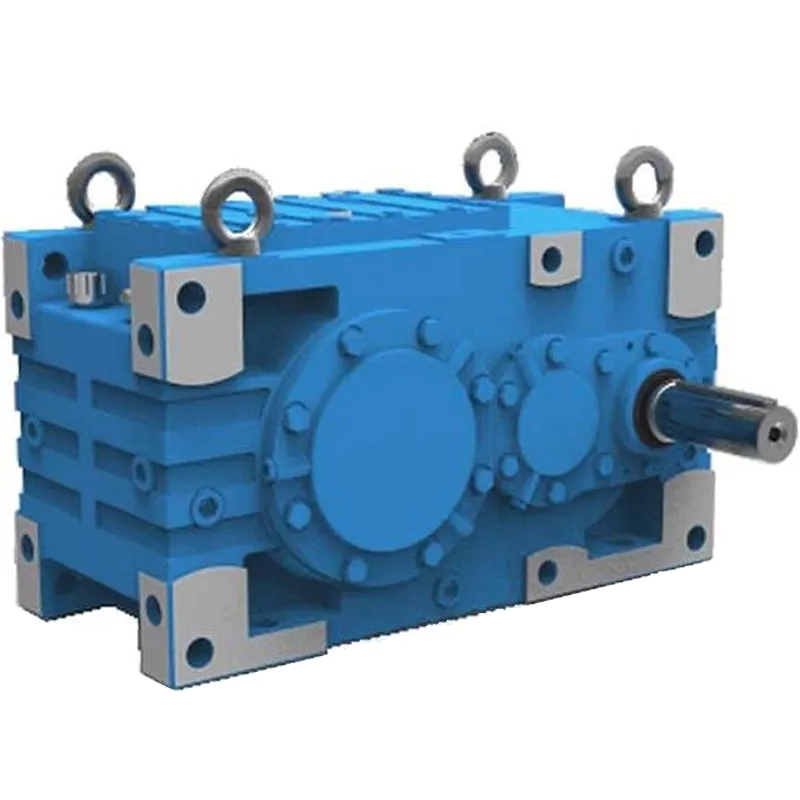
Can you explain the different types of gear reducers available in the market?
There are several types of gear reducers commonly used in industrial applications:
1. Spur Gear Reducers: These reducers have straight teeth and are cost-effective for applications requiring moderate torque and speed reduction. They are efficient but may produce more noise compared to other types.
2. Helical Gear Reducers: Helical gears have angled teeth, which provide smoother and quieter operation compared to spur gears. They offer higher torque capacities and are suitable for heavy-duty applications.
3. Bevel Gear Reducers: Bevel gears have conical shapes and intersect at an angle, allowing them to transmit power between non-parallel shafts. They are commonly used in applications where shafts intersect at 90 degrees.
4. Worm Gear Reducers: Worm gears consist of a worm (screw) and a mating gear (worm wheel). They offer high torque reduction and are used for applications requiring high ratios, although they can be less efficient.
5. Planetary Gear Reducers: These reducers use a system of planetary gears to achieve high torque output in a compact design. They provide excellent torque multiplication and are commonly used in robotics and automation.
6. Cycloidal Gear Reducers: Cycloidal drives use an eccentric cam to achieve speed reduction. They offer high shock load resistance and are suitable for applications with frequent starting and stopping.
7. Harmonic Drive Reducers: Harmonic drives use a flexible spline to achieve high gear reduction ratios. They provide high precision and are commonly used in applications requiring accurate positioning.
8. Hypoid Gear Reducers: Hypoid gears have helical teeth and non-intersecting shafts, making them suitable for applications with space limitations. They offer high torque and efficiency.
Each type of gear reducer has its own advantages and limitations, and the choice depends on factors such as torque requirements, speed ratios, noise levels, space constraints, and application-specific needs.


editor by CX 2024-04-25
China Professional NMRV090 Worm Gear Reducer with Square Flange gearbox drive shaft
Product Description
RV series Characteristics
- RV – Sizes:–150
- Input Options: with input shaft, With Square flange,With Input Flange
- Input Power 0.06 to 11 kW
- RV-Size from 030 to 105 in die-cast aluminium alloy budy and over 110 in cast iron
- Ratios between 5 and 100
- Max torque 1550 N.m and admissible output radial loads max 8771 N
- Aluminium units are supplied complete with synthetic oil and allow for universal mounting positions, with no need to modify lubricant quantity
- Worm wheel: Copper (KK Cu).
- Loading capacity in accordance with: ISO 9001:2015/GB/T 19001-2016
- Size 030 and over are painted with RAL 5571 blue
- Worm gear reducers are available with diffferent combinations: NMRV+NMRV, NMRVpower+NMRV, JWB+NMRV
- NMRV, NRV+VS,NMRV+AS,NMRV+VS,NMRV+F
- Options: torque arm, output flange, viton oil seals, low/high temperature oil, filling/drain/breather/level plug,Small gap
Basic models can be applied to a wide range of power reduction ratios from 5 to 1000.
Warranty: One year from date of delivery.
| WORM GEARBOX | |||||
| SNW SERIES | Output Speed Range: | ||||
| Type | Old Type | Output Torque | Output Shaft Dia. | 14rpm-280rpm | |
| SNW030 | RV030 | 21N.m | φ14 | Applicable Motor Power: | |
| SNW040 | RV040 | 45N.m | φ19 | 0.06kW-11kW | |
| SNW050 | RV050 | 84N.m | φ25 | Input Options1: | |
| SNW063 | RV063 | 160N.m | φ25 | With Inline AC Motor | |
| SNW075 | RV075 | 230N.m | φ28 | Input Options2: | |
| SNW090 | RV090 | 410N.m | φ35 | With Square flange | |
| SNW105 | RV105 | 630N.m | φ42 | Input Options3: | |
| SNW110 | RV110 | 725N.m | φ42 | With Input Shaft | |
| SNW130 | RV130 | 1050N.m | φ45 | Input Options4: | |
| SNW150 | RV150 | 1550N.m | φ50 | With Input Flange |
Starshine Drive
ZheJiang CHINAMFG Drive Co.,Ltd,the predecessor was a state-owned military mould enterprise, was established in 1965. CHINAMFG specializes in the complete power transmission solution for high-end equipment manufacturing industries based on the aim of “Platform Product, Application Design and Professional Service”.
CHINAMFG have a strong technical force with over 350 employees at present, including over 30 engineering technicians, 30 quality inspectors, covering an area of 80000 square CHINAMFG and kinds of advanced processing machines and testing equipments. We have a good foundation for the industry application development and service of high-end speed reducers & variators owning to the provincial engineering technology research center,the lab of gear speed reducers, and the base of modern R&D.
Our Team
Quality Control
Quality:Insist on Improvement,Strive for Excellence With the development of equipment manufacturing indurstry,customer never satirsfy with the current quality of our products,on the contrary,wcreate the value of quality.
Quality policy:to enhance the overall level in the field of power transmission
Quality View:Continuous Improvement , pursuit of excellence
Quality Philosophy:Quality creates value
3. Incoming Quality Control
To establish the AQL acceptable level of incoming material control, to provide the material for the whole inspection, sampling, immunity. On the acceptance of qualified products to warehousing, substandard goods to take return, check, rework, rework inspection; responsible for tracking bad, to monitor the supplier to take corrective measures
to prevent recurrence.
4. Process Quality Control
The manufacturing site of the first examination, inspection and final inspection, sampling according to the requirements of some projects, judging the quality change trend;
found abnormal phenomenon of manufacturing, and supervise the production department to improve, eliminate the abnormal phenomenon or state.
5. FQC(Final QC)
After the manufacturing department will complete the product, stand in the customer’s position on the finished product quality verification, in order to ensure the quality of
customer expectations and needs.
6. OQC(Outgoing QC)
After the product sample inspection to determine the qualified, allowing storage, but when the finished product from the warehouse before the formal delivery of the goods, there is a check, this is called the shipment inspection.Check content:In the warehouse storage and transfer status to confirm, while confirming the delivery of the product
is a product inspection to determine the qualified products.
Packing
Delivery
/* January 22, 2571 19:08:37 */!function(){function s(e,r){var a,o={};try{e&&e.split(“,”).forEach(function(e,t){e&&(a=e.match(/(.*?):(.*)$/))&&1
| Application: | Motor, Machinery |
|---|---|
| Hardness: | Soft Tooth Surface |
| Installation: | 90 Degree |
| Layout: | 90 Degree |
| Gear Shape: | Conical – Cylindrical Gear |
| Step: | Double-Step |
| Customization: |
Available
| Customized Request |
|---|

What are the considerations for choosing the appropriate lubrication for gear reducers?
Choosing the appropriate lubrication for gear reducers is crucial for ensuring optimal performance, longevity, and efficiency. Several considerations should be taken into account when selecting the right lubrication:
1. Load and Torque: The magnitude of the load and torque transmitted by the gear reducer affects the lubrication’s viscosity and film strength requirements. Heavier loads may necessitate higher viscosity lubricants.
2. Operating Speed: The speed at which the gear reducer operates impacts the lubrication’s ability to maintain a consistent and protective film between gear surfaces.
3. Temperature Range: Consider the temperature range of the operating environment. Lubricants with suitable viscosity indexes are crucial to maintaining performance under varying temperature conditions.
4. Contaminant Exposure: If the gear reducer is exposed to dust, dirt, water, or other contaminants, the lubrication should have proper sealing properties and resistance to contamination.
5. Lubrication Interval: Determine the desired maintenance interval. Some lubricants require more frequent replacement, while others offer extended operational periods.
6. Compatibility with Materials: Ensure that the chosen lubricant is compatible with the materials used in the gear reducer, including gears, bearings, and seals.
7. Noise and Vibration: Some lubricants have properties that can help reduce noise and dampen vibrations, improving the overall user experience.
8. Environmental Impact: Consider environmental regulations and sustainability goals when selecting lubricants.
9. Manufacturer Recommendations: Follow the manufacturer’s recommendations and guidelines for lubrication type, viscosity grade, and maintenance intervals.
10. Monitoring and Analysis: Implement a lubrication monitoring and analysis program to assess lubricant condition and performance over time.
By carefully evaluating these considerations and consulting with lubrication experts, industries can choose the most suitable lubrication for their gear reducers, ensuring reliable and efficient operation.

What factors should be considered when selecting the right gear reducer?
Choosing the appropriate gear reducer involves considering several crucial factors to ensure optimal performance and efficiency for your specific application:
- 1. Torque and Power Requirements: Determine the amount of torque and power your machinery needs for its operation.
- 2. Speed Ratio: Calculate the required speed reduction or increase to match the input and output speeds.
- 3. Gear Type: Select the appropriate gear type (helical, bevel, worm, planetary, etc.) based on your application’s torque, precision, and efficiency requirements.
- 4. Mounting Options: Consider the available space and the mounting configuration that suits your machinery.
- 5. Environmental Conditions: Evaluate factors such as temperature, humidity, dust, and corrosive elements that may impact the gear reducer’s performance.
- 6. Efficiency: Assess the gear reducer’s efficiency to minimize power losses and improve overall system performance.
- 7. Backlash: Consider the acceptable level of backlash or play between gear teeth, which can affect precision.
- 8. Maintenance Requirements: Determine the maintenance intervals and procedures necessary for reliable operation.
- 9. Noise and Vibration: Evaluate noise and vibration levels to ensure they meet your machinery’s requirements.
- 10. Cost: Compare the initial cost and long-term value of different gear reducer options.
By carefully assessing these factors and consulting with gear reducer manufacturers, engineers and industry professionals can make informed decisions to select the right gear reducer for their specific application, optimizing performance, longevity, and cost-effectiveness.

Can you explain the different types of gear reducers available in the market?
There are several types of gear reducers commonly used in industrial applications:
1. Spur Gear Reducers: These reducers have straight teeth and are cost-effective for applications requiring moderate torque and speed reduction. They are efficient but may produce more noise compared to other types.
2. Helical Gear Reducers: Helical gears have angled teeth, which provide smoother and quieter operation compared to spur gears. They offer higher torque capacities and are suitable for heavy-duty applications.
3. Bevel Gear Reducers: Bevel gears have conical shapes and intersect at an angle, allowing them to transmit power between non-parallel shafts. They are commonly used in applications where shafts intersect at 90 degrees.
4. Worm Gear Reducers: Worm gears consist of a worm (screw) and a mating gear (worm wheel). They offer high torque reduction and are used for applications requiring high ratios, although they can be less efficient.
5. Planetary Gear Reducers: These reducers use a system of planetary gears to achieve high torque output in a compact design. They provide excellent torque multiplication and are commonly used in robotics and automation.
6. Cycloidal Gear Reducers: Cycloidal drives use an eccentric cam to achieve speed reduction. They offer high shock load resistance and are suitable for applications with frequent starting and stopping.
7. Harmonic Drive Reducers: Harmonic drives use a flexible spline to achieve high gear reduction ratios. They provide high precision and are commonly used in applications requiring accurate positioning.
8. Hypoid Gear Reducers: Hypoid gears have helical teeth and non-intersecting shafts, making them suitable for applications with space limitations. They offer high torque and efficiency.
Each type of gear reducer has its own advantages and limitations, and the choice depends on factors such as torque requirements, speed ratios, noise levels, space constraints, and application-specific needs.


editor by CX 2024-04-17
China Best Sales Hot Sale Worm Gear Reducer From China Factory gearbox drive shaft
Product Description
Technical Features
The high degree of modularity is a design feature of SRC helical gearboxes range. It can be connected respectively with motors such as normal motor, brake motor, explosion-proof motor, frequency conversion motor, servo motor, IEC motor and so on. This kind of product is widely used in drive fields such as textile, foodstuff, ceramics packing, logistics, plastics and so on. It is possible to set up the version required using flanges or feet.
Products characteristics
SRC series helical gear units has more than 4 types. Power 0.12-4kw; Ratio 3.66-54; Torque max 120-500Nm. It can be connected (foot or flange) discretionary and use multi-mounting positions according to customers requirements.
Ground-hardened helical gears;
Modularity,can be combined in many forms;
Aluminium casing, light weight;
Gears in carbonize hard, durable;
Universal mounting;
Refined design,space effective and low noise
Structure feature
Model illuminate
|
1 |
Code for gear units series |
|
2 |
No F code means foot mounted.With F code B5 flange mounted.With Z code B14 flange mounted |
|
3 |
Specification code of gear units 01 |
|
4 |
I,II,III,B5 Output flange specification,default I not to write out is ok |
|
5 |
IEC: Input flange HS: shaft input |
|
6 |
Transmission ratio of gear units |
|
7 |
M1:Mounting position, default mounting position M1 not to write out is ok |
|
8 |
Position diagram for motor terminal box,default position o°(R) not to write out is ok |
|
9 |
No mark means without motor Model motor(poles of power) |
|
10 |
Voltage – frequency |
|
11 |
Coil in position for motor, default position S not to write out is ok |
4.2 Rotation speed n
n1 Gear units input speed
n2 Gear units output speed
If driven by the external gearing,1400r/min or lower rotation speed is suggested so as to optimize the working conditions and prolong the service life.Higher input rotation speed is permitted, but in this situation,the rated torque M2 will be reduced
4.5 Service factor fs
The effect of the driven machine on the gear unit is taken into account to a sufficient level of accuracy using the service factor fs. The service factor is determined according to the daily operation time and the starting frequency Z. Three load classifications are considered depending on the mass acceleration factor. You can read off the service factor applicable to your application in following figure. The service factor selected using this diagram must be less than or equal to the service factor as given in the performance parameter table.
* starting frequency Z: The cycles include all starting and braking procedures as well as change overs from low to high speed
SRC02..(HS) Performance parameter
|
kw |
Output speed |
Torque |
Speed ratio |
fs |
Model |
IEC |
|
0.37 |
16.7rpm |
204N.M |
54 |
1.0 |
SRC02 |
80B5/B14
|
Helical gearbox outline dimension heet
| Foot Code | U | V | V1 | V2 | V3 | W | X | X1 | Y | Z |
| B02 | 18 | 107.5 | 60 | – | 130 | 11 | 136 | 155 | 100 | 17 |
| M02 | 25 | 85 | – | 110 | 120 | 9 | 112 | 145 | 80 | 15 |
| M01 | 18 | 80 | – | 110 | 120 | 9 | 118 | 145 | 80 | 15 |
| B01 | 18 | 87 | 50 | 110 | – | 9 | 118 | 130 | 90 | 15 |
SRC helical gearbox with motor mounting position and terminal box orientation
Package
1 pc / carton,several cartons / wooden pallet
| Application: | Motor |
|---|---|
| Layout: | Cycloidal |
| Hardness: | Soft Tooth Surface |
| Samples: |
US$ 145.3/Piece
1 Piece(Min.Order) | Order Sample SMRV-110-7.5-132M4
|
|---|
| Customization: |
Available
| Customized Request |
|---|
.shipping-cost-tm .tm-status-off{background: none;padding:0;color: #1470cc}
|
Shipping Cost:
Estimated freight per unit. |
about shipping cost and estimated delivery time. |
|---|
| Payment Method: |
|
|---|---|
|
Initial Payment Full Payment |
| Currency: | US$ |
|---|
| Return&refunds: | You can apply for a refund up to 30 days after receipt of the products. |
|---|
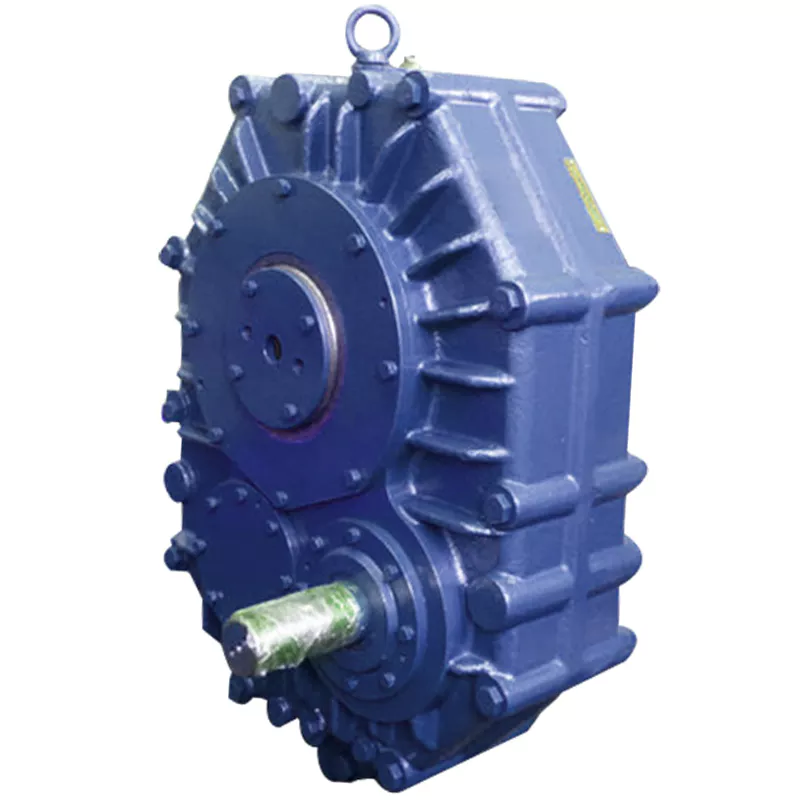
Are there any disadvantages or limitations to using gear reducer systems?
While gear reducer systems offer numerous advantages, they also come with certain disadvantages and limitations that should be considered during the selection and implementation process:
1. Size and Weight: Gear reducers can be bulky and heavy, especially for applications requiring high gear ratios. This can impact the overall size and weight of the machinery or equipment, which may be a concern in space-constrained environments.
2. Efficiency Loss: Despite their high efficiency, gear reducers can experience energy losses due to friction between gear teeth and other components. This can lead to a reduction in overall system efficiency, particularly in cases where multiple gear stages are used.
3. Cost: The design, manufacturing, and assembly of gear reducers can involve complex processes and precision machining, which can contribute to higher initial costs compared to other power transmission solutions.
4. Maintenance: Gear reducer systems require regular maintenance, including lubrication, inspection, and potential gear replacement over time. Maintenance activities can lead to downtime and associated costs in industrial settings.
5. Noise and Vibration: Gear reducers can generate noise and vibrations, especially at high speeds or when operating under heavy loads. Additional measures may be needed to mitigate noise and vibration issues.
6. Limited Gear Ratios: While gear reducers offer a wide range of gear ratios, there may be limitations in achieving extremely high or low ratios in certain designs.
7. Temperature Sensitivity: Extreme temperatures can affect the performance of gear reducer systems, particularly if inadequate lubrication or cooling is provided.
8. Shock Loads: While gear reducers are designed to handle shock loads to some extent, severe shock loads or abrupt changes in torque can still lead to potential damage or premature wear.
Despite these limitations, gear reducer systems remain widely used and versatile components in various industries, and their disadvantages can often be mitigated through proper design, selection, and maintenance practices.

What role do gear ratios play in optimizing the performance of gear reducers?
Gear ratios play a crucial role in optimizing the performance of gear reducers by determining the relationship between input and output speeds and torques. A gear ratio is the ratio of the number of teeth between two meshing gears, and it directly influences the mechanical advantage and efficiency of the gear reducer.
1. Speed and Torque Conversion: Gear ratios allow gear reducers to convert rotational speed and torque according to the needs of a specific application. By selecting appropriate gear ratios, gear reducers can either reduce speed while increasing torque (speed reduction) or increase speed while decreasing torque (speed increase).
2. Mechanical Advantage: Gear reducers leverage gear ratios to provide mechanical advantage. In speed reduction configurations, a higher gear ratio results in a greater mechanical advantage, allowing the output shaft to deliver higher torque at a lower speed. This is beneficial for applications requiring increased force or torque, such as heavy machinery or conveyor systems.
3. Efficiency: Optimal gear ratios contribute to higher efficiency in gear reducers. By distributing the load across multiple gear teeth, gear reducers with suitable gear ratios minimize stress and wear on individual gear teeth, leading to improved overall efficiency and prolonged lifespan.
4. Speed Matching: Gear ratios enable gear reducers to match the rotational speeds of input and output shafts. This is crucial in applications where precise speed synchronization is required, such as in conveyors, robotics, and manufacturing processes.
When selecting gear ratios for a gear reducer, it’s important to consider the specific requirements of the application, including desired speed, torque, efficiency, and mechanical advantage. Properly chosen gear ratios enhance the overall performance and reliability of gear reducers in a wide range of industrial and mechanical systems.

Function of Gear Reducers in Mechanical Systems
A gear reducer, also known as a gear reduction unit or gearbox, is a mechanical device designed to reduce the speed of an input shaft while increasing its torque output. It accomplishes this through the use of a set of interlocking gears with different sizes.
The primary function of a gear reducer in mechanical systems is to:
- Speed Reduction: The gear reducer takes the high-speed rotation of the input shaft and transmits it to the output shaft through a set of gears. The gears are configured in such a way that the output gear has a larger diameter than the input gear. As a result, the output shaft rotates at a lower speed than the input shaft, but with increased torque.
- Torque Increase: Due to the size difference between the input and output gears, the torque applied to the output shaft is greater than that of the input shaft. This torque multiplication allows the system to handle heavier loads and perform tasks requiring higher force.
Gear reducers are widely used in various industries and applications where it’s necessary to adapt the speed and torque characteristics of a power source to meet the requirements of the driven equipment. They can be found in machinery such as conveyor systems, industrial machinery, vehicles, and more.


editor by CX 2023-10-21
China supplier Truck Crane Tow Truck Wrecker Slew Drive Worm Speed Reducer Hydraulic Slewing Gearbox Planetary Gear Motor Reducer with Best Sales
Product Description
HangZhou CHINAMFG Machinery Co., Ltd.has been specialising in the manufacture and export of RV series worm gearboxes and other power transmission products for years, dedicated to provide to our customers good quality products in competitive prices. The main products are RV series worm gear speed reducers, UD series mechanical speed variators, G3 series helical geared motors and the specially designed reducers for polishing machines. Our products are widely used in the mechanical apparatus for foodstuff, ceramics, package, chemical, printing, and plastics, etc.
Xihu (West Lake) Dis.d by the idea, “Quality is the very key.”. the company proceeds in strict quality control to all the products, complying with the requirements of ISO9001:2008, and certificated, which has enabled our products to have enjoyed the successful sales, popularity and good reputation among the markets of Europe, Mid-east, and Souteast Asia..
Innovation, good quality, customers’ satisfication, and excellent service are the principles of the company. All customers at home and abroad are warmly welcome to contact us and negotiate for mutual business expansion.
|
Shipping Cost:
Estimated freight per unit. |
To be negotiated |
|---|
| Application: | Motor, Electric Cars, Motorcycle, Machinery, Marine, Toy, Agricultural Machinery, Car |
|---|---|
| Function: | Distribution Power, Clutch, Change Drive Torque, Change Drive Direction, Speed Changing, Speed Reduction, Speed Increase |
| Layout: | Cycloidal |
| Samples: |
US$ 30/Piece
1 Piece(Min.Order) | Order Sample |
|---|
| Customization: |
Available
| Customized Request |
|---|

Can gear reducers be customized for specific industrial needs and requirements?
Yes, gear reducers can be customized to meet specific industrial needs and requirements. Manufacturers offer customization options to ensure that gear reducers are tailored to the unique demands of various applications:
1. Gear Ratio Selection: Gear reducers can be designed with specific gear ratios to achieve the desired speed reduction or increase, catering to the specific requirements of the machinery or equipment.
2. Shaft Configurations: Gear reducers can be configured with different shaft sizes, lengths, and orientations to fit seamlessly into existing systems or accommodate specific mounting arrangements.
3. Torque Capacity: Customized gear reducers can be designed to handle higher or lower torque loads based on the application’s operational requirements.
4. Environmental Considerations: Gear reducers can be customized with special coatings, materials, or seals to withstand harsh environments, extreme temperatures, or corrosive conditions.
5. Noise and Vibration Reduction: Custom designs can incorporate features to reduce noise and dampen vibrations, enhancing the overall operation and user experience.
6. Mounting and Connection Options: Manufacturers can adapt gear reducer designs to include specific mounting interfaces or connection methods that align with the equipment’s design.
7. Lubrication and Maintenance: Customized gear reducers can include features for easy maintenance, such as accessible lubrication points or monitoring systems.
8. Integration with Controls: Gear reducers can be customized to integrate seamlessly with control systems, sensors, or automation processes, enhancing system efficiency and performance.
By collaborating with manufacturers and providing detailed specifications, industries can obtain tailor-made gear reducers that address their specific operational needs and contribute to the success of their applications.

What role do gear ratios play in optimizing the performance of gear reducers?
Gear ratios play a crucial role in optimizing the performance of gear reducers by determining the relationship between input and output speeds and torques. A gear ratio is the ratio of the number of teeth between two meshing gears, and it directly influences the mechanical advantage and efficiency of the gear reducer.
1. Speed and Torque Conversion: Gear ratios allow gear reducers to convert rotational speed and torque according to the needs of a specific application. By selecting appropriate gear ratios, gear reducers can either reduce speed while increasing torque (speed reduction) or increase speed while decreasing torque (speed increase).
2. Mechanical Advantage: Gear reducers leverage gear ratios to provide mechanical advantage. In speed reduction configurations, a higher gear ratio results in a greater mechanical advantage, allowing the output shaft to deliver higher torque at a lower speed. This is beneficial for applications requiring increased force or torque, such as heavy machinery or conveyor systems.
3. Efficiency: Optimal gear ratios contribute to higher efficiency in gear reducers. By distributing the load across multiple gear teeth, gear reducers with suitable gear ratios minimize stress and wear on individual gear teeth, leading to improved overall efficiency and prolonged lifespan.
4. Speed Matching: Gear ratios enable gear reducers to match the rotational speeds of input and output shafts. This is crucial in applications where precise speed synchronization is required, such as in conveyors, robotics, and manufacturing processes.
When selecting gear ratios for a gear reducer, it’s important to consider the specific requirements of the application, including desired speed, torque, efficiency, and mechanical advantage. Properly chosen gear ratios enhance the overall performance and reliability of gear reducers in a wide range of industrial and mechanical systems.

Function of Gear Reducers in Mechanical Systems
A gear reducer, also known as a gear reduction unit or gearbox, is a mechanical device designed to reduce the speed of an input shaft while increasing its torque output. It accomplishes this through the use of a set of interlocking gears with different sizes.
The primary function of a gear reducer in mechanical systems is to:
- Speed Reduction: The gear reducer takes the high-speed rotation of the input shaft and transmits it to the output shaft through a set of gears. The gears are configured in such a way that the output gear has a larger diameter than the input gear. As a result, the output shaft rotates at a lower speed than the input shaft, but with increased torque.
- Torque Increase: Due to the size difference between the input and output gears, the torque applied to the output shaft is greater than that of the input shaft. This torque multiplication allows the system to handle heavier loads and perform tasks requiring higher force.
Gear reducers are widely used in various industries and applications where it’s necessary to adapt the speed and torque characteristics of a power source to meet the requirements of the driven equipment. They can be found in machinery such as conveyor systems, industrial machinery, vehicles, and more.


editor by CX 2023-10-07
China OEM Aluminum Cast Iron Housing Transmission Drive Motor Shaft Smrv Series Reduction Helical Cycloidal Cyclo Planetary Worm Gearboxes gearbox design
Product Description
Worm gearbox speed reducer electric motor dc are on sale with high quality for you
SMRV 571-150 worm gear box with flange and electric motor
SMRV+NMRV Double Stage Arrangement Reduction Gear Box
RV Series Worm Gearbox
worm speed reducer
nmrv worm gear motor
You can choose the 1 type that you need form these product introction.
If you have any question,please contact me.
HangZhou CHINAMFG Machinery Co.,ltd is a company specialized in research, manufacture and service of speed gearbox. Ever since establishment, we have been persisting in technical innovation, advancing the techonology to our products while maintaining our strict quality controls. It is the reason that our products branding ”Xihu (West Lake) Dis.n” have enjoyed such successful global sales.
At present, our company mainly supplies 5 series products as RV worm gearbox, UDL series speed variator,PC series helical gear unit,G3 helical geared motor and SRC helical gearbox. The products are widely applied in the mechanical equipment field such as food and beverage,cement,package,chemical and dyeing, rubber and plastic, CNC machine tool,etc.
Our products have been processed ISO 9001 Quality System Certification and exported to Italy,Spain,Britain,Poland,Turkey.The USA and other European countries,earn the good reputation with our outstanding quality and service.
Customers first,customers satisfaction, excellent after sale service and incessant innovation are our tenet and motto. We will go all out to provide all the customers with high quality and service.
|
Shipping Cost:
Estimated freight per unit. |
To be negotiated |
|---|
| Application: | Motor, Electric Cars, Motorcycle, Machinery, Marine, Toy, Agricultural Machinery, Car |
|---|---|
| Hardness: | Hardened Tooth Surface |
| Installation: | Vertical Type |
| Customization: |
Available
| Customized Request |
|---|
Calculation of Reduction Ratio in a Cycloidal Gearbox
The reduction ratio in a cycloidal gearbox can be calculated using the following formula:
Reduction Ratio = (Number of Input Pins + Number of Output Pins) / Number of Output Pins
In a cycloidal gearbox, the input pins engage with the lobes of the cam disc, while the output pins are engaged with the cycloidal pins of the output rotor. The reduction ratio determines the relationship between the number of input and output pins engaged at any given time.
For example, if a cycloidal gearbox has 7 input pins and 14 output pins engaged, the reduction ratio would be:
Reduction Ratio = (7 + 14) / 14 = 1.5
This means that for every 1 revolution of the input pins, the output rotor will complete 1.5 revolutions. The reduction ratio is a key parameter that influences the output speed and torque of the cycloidal gearbox.
Patents Associated with Cycloidal Gearbox Designs
Throughout the history of cycloidal gearbox development, several patents have been filed for various designs and applications. Some notable patents include:
- Harmonic Drive: Ralph B. Heath’s patent for the “Harmonic Drive” (US Patent 2,906,143), filed in 1957, is one of the most famous patents related to cycloidal gear systems. This patent introduced the concept of a high-precision reduction gear mechanism using flexible components.
- Cycloidal Drive Mechanism: A patent by James Watt for a “Cycloidal Drive Mechanism” (GB Patent 1812), dating back to the 18th century, is often cited as one of the early references to cycloidal motion and gears.
- Planetary Roller Transmission: US Patent 3,671,927 by C.F. Kafesjian and H. Blumenstock introduced a “Planetary Roller Transmission” in 1972, describing a cycloidal drive mechanism with planetary motion.
- Cycloidal Speed Reducer: A patent for a “Cycloidal Speed Reducer” (US Patent 5,588,583) was granted to Richard J. Pieprzak in 1996, focusing on an improved design of cycloidal gears for various applications.
These patents represent a small sample of the numerous innovations and designs related to cycloidal gear systems that have been patented over the years. Patents play a significant role in protecting and promoting innovation in the field of gearbox technology.
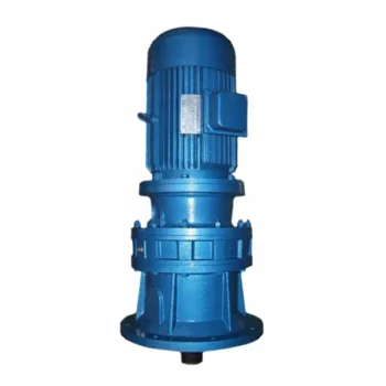
Common Applications of Cycloidal Gearboxes
Cycloidal gearboxes find their application in various industries and scenarios where their unique features are advantageous:
- Robotics: Cycloidal gearboxes are often used in robotic joints and manipulators due to their compact size, high torque capacity, and precision movement.
- Conveyor Systems: Their ability to handle heavy loads and provide accurate motion makes cycloidal gearboxes suitable for conveyor systems in industries such as manufacturing, food processing, and material handling.
- Aerospace: In aerospace applications, cycloidal gearboxes are used in satellite mechanisms, aerospace actuators, and precision motion control systems.
- Medical Devices: The compact design and precise motion capabilities of cycloidal gearboxes are beneficial in medical equipment such as surgical robots and diagnostic devices.
- Textile Industry: Cycloidal gearboxes are utilized in textile machines for their ability to provide accurate and synchronized movement in the weaving and knitting processes.
- Automotive: Some automotive applications, such as sunroof mechanisms and power seats, can benefit from the compact size and high torque capacity of cycloidal gearboxes.
- Printing Industry: The precision and reliability of cycloidal gearboxes are important in printing presses to ensure accurate paper feeding and positioning.
- Packaging Machinery: In packaging equipment, cycloidal gearboxes can provide the required torque and accuracy for tasks like sealing, labeling, and filling.
These are just a few examples of where cycloidal gearboxes are commonly used, demonstrating their versatility and adaptability across various industries.


editor by CX 2023-09-18
China Best Sales Speed Gear Reducer Bevel Helical Agricultural Cycloidal Drive Worm Gearbox gearbox definition
Product Description
ZheJiang CZPT Machinery Manufacturing Co.,LTD. is an innovative manufacturing enterprise specalizing in the production, design, sales and installation of bulk material conveying equipment.
The company mainly provides belt conveyor, tubular belt conveyor, mobile belt conveyor, screw conveyor, Bucket Elevator, chain conveyor, scraper conveyor and other material handling conveying equipment. It also provides conveyor idlers rollers,conveyor drum pulleys,conveyor belts, belt cleaners,impact beds,take-up frame and other components.
Juntong Conveyor has many years of experience in supplying to a diverse range of industries which includes coal, cement,steel iron, chemical,agricultural, power,mining, port, quarrying,mechanical & civil engineering, waste management & recycling.
We have a professional R&D team with plenty technical patents.and we can produce conveyor products in different standards such as CEMA, JIS, ISO, AS, GB and so on. Also,our products have already qualified IS09001, CE, SGS, BV, MA certifications,In addition, CZPT has established friendly and cooperative relationships with ZheJiang Material Handling Research Institute Co.,ltd( BMHRI), CZPT Research Institute (CCRI), HangZhou University of Science and Technology (TYUST) , etc., so that the company’s research and development level has always been at the forefront of innovation in the field of bulk material transportation.CZPT Conveyor has became a CZPT brand with great reputation for providing total conveyor confidence.
|
Shipping Cost:
Estimated freight per unit. |
To be negotiated |
|---|
| After-sales Service: | Warranty Service |
|---|---|
| Warranty: | 1 Year |
| Output Torque: | 800~100000n.M |
| Samples: |
US$ 0/Piece
1 Piece(Min.Order) | Order Sample |
|---|
| Customization: |
Available
| Customized Request |
|---|
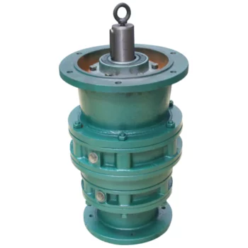
Distinguishing Features of Cycloidal Gearboxes
Cycloidal gearboxes, also known as cycloidal drives or cycloidal reducers, possess distinct characteristics that set them apart from other types of gearboxes:
- Principle of Operation: Cycloidal gearboxes utilize the principle of cycloidal motion, where input shaft movement is transformed into eccentric motion of the cycloidal disc. This unique mechanism results in smooth and consistent output motion.
- Compactness: Cycloidal gearboxes are renowned for their compact size and high torque density. The concentric design of the components contributes to their ability to transmit substantial torque in a relatively small package.
- Tooth Profile: Cycloidal gearboxes employ specialized cycloidal teeth, which involve both pinwheel and roller gears. This distinctive tooth profile contributes to the characteristic smooth and vibration-free operation.
- Reduction Mechanism: They often employ multi-lobed cam gears that interact with the pins on the cycloidal disc, resulting in multiple gear engagements per revolution and improved load distribution.
- Motion Control: Cycloidal gearboxes offer high positional accuracy and motion control due to the eccentric motion of the disc, making them suitable for robotics, automation, and precision applications.
- Backlash: They typically exhibit low backlash due to the nature of the engagement mechanism, making them advantageous for applications requiring precise and reversible motion.
- Applications: Cycloidal gearboxes are commonly used in various industries, including robotics, packaging, material handling, printing, and more, where their compactness, precision, and efficiency are valued.
These distinguishing features contribute to the unique capabilities and benefits of cycloidal gearboxes in specific applications.
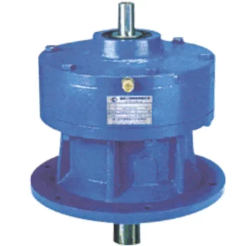
Maintenance Requirements for Cycloidal Gearboxes
Maintaining cycloidal gearboxes is essential to ensure their optimal performance and longevity. Here are some maintenance practices to consider:
- Lubrication: Regular lubrication is crucial to prevent wear and friction between moving parts. Use high-quality lubricants recommended by the gearbox manufacturer.
- Inspections: Regularly inspect the gearbox for signs of wear, damage, or oil leakage. Address any issues promptly to prevent further damage.
- Cleaning: Keep the gearbox clean and free from debris that could interfere with its operation. Cleanliness helps prevent contamination and wear.
- Torque Checks: Periodically check the tightness of fasteners and bolts to ensure they are properly secured. Loose fasteners can lead to misalignment and reduced performance.
- Seal Maintenance: Check and maintain seals to prevent oil leakage. Damaged seals should be replaced promptly to avoid lubricant loss.
- Temperature Monitoring: Monitor the operating temperature of the gearbox to ensure it remains within the recommended range. Excessive heat can lead to premature wear.
- Alignment: Ensure that the gearbox is properly aligned with other components to prevent misalignment-related issues.
- Regular Service: Follow the manufacturer’s recommended service intervals for more in-depth inspections and maintenance tasks.
Regular and proactive maintenance can extend the lifespan of cycloidal gearboxes, minimize downtime, and maintain their efficiency and performance over time.
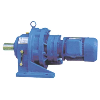
Advantages of Using a Cycloidal Gearbox
Cycloidal gearboxes offer several advantages that make them well-suited for various applications:
- High Torque Density: Cycloidal gearboxes provide a high torque output relative to their size and weight. This makes them ideal for applications where space is limited, and high torque is required.
- Compact Design: The unique arrangement of cycloidal pins and lobed profiles results in a compact gearbox design. This is advantageous when dealing with constrained installation spaces.
- Smooth and Precise Motion: Cycloidal motion generates smooth and controlled movement, making these gearboxes suitable for applications requiring accurate positioning, such as robotics and automation.
- High Shock Load Capacity: The multiple points of contact between the cycloidal pins and the lobes distribute the load, allowing cycloidal gearboxes to handle sudden shocks and overloads effectively.
- Backlash Elimination: Cycloidal gearboxes exhibit minimal backlash due to the nature of their motion. This is beneficial in applications where precise motion reversal is crucial.
- High Efficiency: The rolling contact between the pins and lobes contributes to efficient power transmission, resulting in relatively high efficiency levels.
- Reduced Wear and Noise: The rolling motion in cycloidal gearboxes leads to reduced wear on components, resulting in lower maintenance requirements and quieter operation.
- Versatility: Cycloidal gearboxes can handle a wide range of ratios and speeds, making them suitable for various industrial and automation applications.
Due to these advantages, cycloidal gearboxes are commonly used in robotics, automation, packaging machinery, conveyors, and other applications where compactness, high torque, and precise motion are critical.


editor by CX 2023-09-11