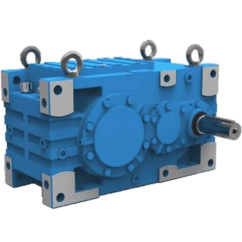
Product Description
Detailed Photos
Features of S series reducer
The same model can be equipped with motors of various powers. It is easy to realize the combination and connection between various models.
The transmission efficiency is high, and the single reducer efficiency is up to 96%. three
The transmission ratio is subdivided and the range is wide. The combined model can form a large transmission ratio and low output speed.
The installation forms are various, and can be installed with any foot, B5 flange or B4 flange. The foot mounting reducer has 2 machined foot mounting planes.
Helical gear and worm gear combination, compact structure, large reduction ratio.
Installation mode: foot installation, hollow shaft installation, flange installation, torque arm installation, small flange installation.
Input mode: motor direct connection, motor belt connection or input shaft, connection flange input.
Average efficiency: reduction ratio 7.5-69.39 is 77%; 70.43-288 is 62%; The S/R combination is 57%.
S57 SF57 SA57 SAF57 S series helical worm gear box speed reducer 0.18kw 0.25kw 0.37kw 0.55kw 0.75kw 1.1kw 1.5kw 2.2kw 3kw, max. permissible torque up to 300Nm, transmission ratios from 10.78 to 196.21. Mounting mode: foot mounted, flange mounted, short flange mounted, torque arm mounted. Output shaft: CHINAMFG shaft, hollow shaft (with key, with shrink disc and with involute spline).
Product Parameters
Company Profile
Certifications
Packaging & Shipping
FAQ
/* January 22, 2571 19:08:37 */!function(){function s(e,r){var a,o={};try{e&&e.split(“,”).forEach(function(e,t){e&&(a=e.match(/(.*?):(.*)$/))&&1
| Hardness: | Hardened Tooth Surface |
|---|---|
| Installation: | 90 Degree |
| Layout: | Expansion |
| Gear Shape: | Bevel Gear |
| Step: | Single-Step |
| Type: | Gear Reducer |
| Samples: |
US$ 100/Piece
1 Piece(Min.Order) | |
|---|
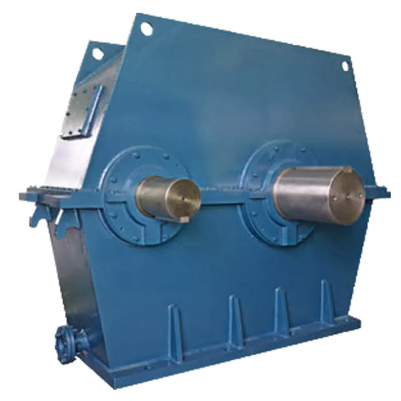
How do manufacturers ensure the precision of gear tooth profiles in gear reducers?
Manufacturers employ several techniques to ensure the precision of gear tooth profiles in gear reducers, which is crucial for optimal performance and efficiency:
1. Precision Machining: Gear teeth are typically machined using advanced CNC (Computer Numerical Control) machines that can achieve high levels of accuracy and repeatability. This ensures consistent gear tooth profiles across multiple components.
2. Quality Control Measures: Rigorous quality control processes, such as dimensional inspections and profile measurements, are performed at various stages of manufacturing to verify that gear tooth profiles meet the required specifications.
3. Tooth Profile Design: Engineers use specialized software and simulation tools to design gear tooth profiles with precise involute shapes and accurate dimensions. These designs are then translated into machine instructions for manufacturing.
4. Material Selection: High-quality materials with excellent wear resistance and dimensional stability are chosen to minimize the potential for deformation or inaccuracies during machining and operation.
5. Heat Treatment: Heat treatment processes, such as carburizing and quenching, are applied to enhance the surface hardness and durability of gear teeth, reducing the risk of wear and deformation over time.
6. Tooth Grinding and Finishing: After initial machining, gear teeth often undergo precision grinding and finishing processes to achieve the desired tooth profile accuracy and surface finish.
7. Post-Processing Inspection: Gear tooth profiles are inspected again after manufacturing processes to verify that the final components meet the specified tolerances and performance criteria.
8. Computer-Aided Manufacturing (CAM): CAM software is used to generate tool paths and machining instructions, enabling precise control over tool movements and material removal during gear manufacturing.
By combining these techniques and leveraging advanced manufacturing technologies, manufacturers can achieve the necessary precision in gear tooth profiles, resulting in reliable and efficient gear reducers for various industrial applications.
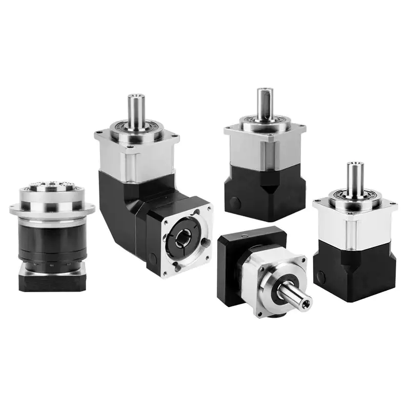
Can gear reducers be used for both speed reduction and speed increase?
Yes, gear reducers can be utilized for both speed reduction and speed increase, depending on their design and arrangement. The functionality to either decrease or increase rotational speed is achieved by altering the arrangement of gears within the gearbox.
1. Speed Reduction: In speed reduction applications, a gear reducer is designed with gears of different sizes. The input shaft connects to a larger gear, while the output shaft is connected to a smaller gear. As the input shaft rotates, the larger gear turns the smaller gear, resulting in a decrease in output speed compared to the input speed. This configuration provides higher torque output at a lower speed, making it suitable for applications that require increased force or torque.
2. Speed Increase: For speed increase, the gear arrangement is reversed. The input shaft connects to a smaller gear, while the output shaft is connected to a larger gear. As the input shaft rotates, the smaller gear drives the larger gear, resulting in an increase in output speed compared to the input speed. However, the torque output is lower than that of speed reduction configurations.
By choosing the appropriate gear ratios and arrangement, gear reducers can be customized to meet specific speed and torque requirements for various industrial applications. It’s important to select the right type of gear reducer and configure it correctly to achieve the desired speed reduction or speed increase.
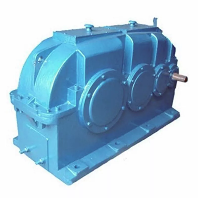
How do gear reducers contribute to speed reduction and torque increase?
Gear reducers play a crucial role in mechanical systems by achieving speed reduction and torque increase through the principle of gear ratios. Here’s how they work:
Gear reducers consist of multiple gears with different sizes, known as gear pairs. These gears are meshed together, and their teeth interlock to transmit motion and power. The gear ratio is determined by the ratio of the number of teeth on the input gear (driver) to the number of teeth on the output gear (driven).
Speed Reduction: When a larger gear (output gear) is driven by a smaller gear (input gear), the output gear rotates at a slower speed than the input gear. This reduction in speed is proportional to the gear ratio. As a result, gear reducers are used to slow down the rotational speed of the output shaft compared to the input shaft.
Torque Increase: The interlocking teeth of gears create a mechanical advantage that allows gear reducers to increase torque output. When the input gear applies a force (torque) to the teeth, it is transmitted to the output gear with greater force due to the leverage provided by the larger diameter of the output gear. The torque increase is inversely proportional to the gear ratio and is essential for applications requiring high torque at lower speeds.
By selecting appropriate gear ratios and arranging gear pairs, gear reducers can achieve various speed reduction and torque multiplication factors, making them essential components in machinery and equipment where precise control of speed and torque is necessary.


editor by CX 2024-05-09
China Standard Hard Tooth 3 Phase Motor Gearbox Horizontal Gear Box Vertical Geared Worm Reducer with AC Electric Motor for Cruser with Best Sales
Product Description
Hard Tooth 3 Phase Motor Gearbox Horizontal Gear Box Vertical Geared Worm Reducer with AC Electric Motor for Cruser
1. The wide and comprehensive range of N series for industrial applications
2. Low-speed shaft design: Cylindrical with key, splined, hollow with shrink disc or splined hollow shaft
3. Rigid and precise nodular cast iron casing
4. Low noise running, high manufacturing quality standard
5. High and reliable performance, load capacity and low-speed shaft bearing
Please click here for more types!
Our Services
With all our activities DNV-ISO 9001, SGS -certified, we stand for top-quality service. Entrusting your gearboxes to the care of our Services.
Help protect your gearbox from wear and grinding, SGR gearbox converts torque reliably and efficiently.
We customize our CHINAMFG planetary gear units, double enveloping worm gearbox, helical gear motor, modular design helical gear unit, worm gearbox, cycloidal gearbox etc to fit your application and meet your needs.
These features enable a reliable and safe service life of over 200 000 operational hours.
Our customers have been placing their trust in CHINAMFG gear units since 1997. More than 500 000 gear units of our gearbox are in use reliably around the world, in many cases under very harsh conditions.
Related Products
For more reducers and mechanical accessories, please click here to view
| Application: | Motor, Electric Cars, Motorcycle, Machinery, Marine, Toy, Agricultural Machinery, Car |
|---|---|
| Function: | Distribution Power, Speed Changing, Speed Reduction |
| Layout: | Wrom |
| Hardness: | Hardened Tooth Surface |
| Installation: | Worm Reducer |
| Step: | Worm Drive |
Can you provide real-world examples of products that use gear reducer technology?
Certainly! Gear reducer technology is widely used in various industries and products to enhance performance and efficiency. Here are some real-world examples:
1. Industrial Machinery: Gear reducers are commonly used in manufacturing machinery, such as conveyor systems, material handling equipment, and assembly lines, where they help control speed and torque for precise operations.
2. Wind Turbines: Wind turbines utilize gear reducers to transform the low rotational speed of the wind turbine rotor into the higher speed needed for electricity generation, optimizing energy conversion.
3. Automotive Transmissions: Automobiles use gear reducers as part of their transmissions to optimize power delivery from the engine to the wheels, allowing the vehicle to operate efficiently at different speeds.
4. Robotics: Robotic systems rely on gear reducers to control the movement and articulation of robot arms, enabling precise and controlled motion for various applications.
5. Printing Presses: Gear reducers are integral to printing presses, ensuring accurate and synchronized movement of printing plates, rollers, and paper feed mechanisms.
6. Conveyor Belts: Conveyor systems in industries like mining, agriculture, and logistics use gear reducers to regulate the movement of materials along the conveyor belts.
7. Packaging Machinery: Gear reducers play a crucial role in packaging machines, controlling the speed and movement of packaging materials, filling mechanisms, and sealing components.
8. Cranes and Hoists: Cranes and hoists rely on gear reducers to lift heavy loads with precision and control, ensuring safe and efficient material handling.
9. Pumps and Compressors: Gear reducers are utilized in pumps and compressors to regulate fluid flow and pressure, optimizing energy usage in fluid transportation systems.
10. Agriculture Equipment: Tractors and other agricultural machinery use gear reducers to adjust the speed and power delivery for different tasks, such as plowing, planting, and harvesting.
These examples demonstrate the diverse applications of gear reducer technology across various industries, showcasing their role in enhancing efficiency, control, and performance in a wide range of products and systems.

Can gear reducers be used for both speed reduction and speed increase?
Yes, gear reducers can be utilized for both speed reduction and speed increase, depending on their design and arrangement. The functionality to either decrease or increase rotational speed is achieved by altering the arrangement of gears within the gearbox.
1. Speed Reduction: In speed reduction applications, a gear reducer is designed with gears of different sizes. The input shaft connects to a larger gear, while the output shaft is connected to a smaller gear. As the input shaft rotates, the larger gear turns the smaller gear, resulting in a decrease in output speed compared to the input speed. This configuration provides higher torque output at a lower speed, making it suitable for applications that require increased force or torque.
2. Speed Increase: For speed increase, the gear arrangement is reversed. The input shaft connects to a smaller gear, while the output shaft is connected to a larger gear. As the input shaft rotates, the smaller gear drives the larger gear, resulting in an increase in output speed compared to the input speed. However, the torque output is lower than that of speed reduction configurations.
By choosing the appropriate gear ratios and arrangement, gear reducers can be customized to meet specific speed and torque requirements for various industrial applications. It’s important to select the right type of gear reducer and configure it correctly to achieve the desired speed reduction or speed increase.
Are there variations in gear reducer designs for specific tasks and applications?
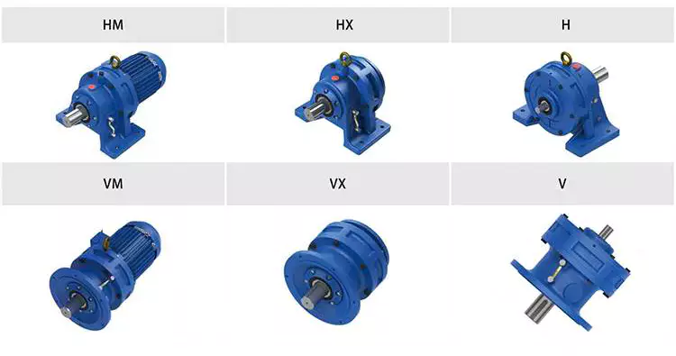
Yes, gear reducer designs vary widely to suit specific tasks and applications across various industries. Manufacturers offer a range of gear reducer types and configurations to accommodate different requirements, including:
- Helical Gear Reducers: These are versatile and provide smooth and efficient torque transmission. They are commonly used in applications requiring high precision and moderate speed reduction, such as conveyors, mixers, and agitators.
- Bevel Gear Reducers: These are ideal for transmitting power between intersecting shafts. They are often used in heavy machinery, printing presses, and automotive applications.
- Worm Gear Reducers: These provide compact solutions and are suitable for applications with higher speed reduction requirements, such as conveyor systems, winches, and elevators.
- Planetary Gear Reducers: These offer high torque density and are used in applications demanding precise control, such as robotics, aerospace, and heavy-duty machinery.
- Parallel Shaft Gear Reducers: Commonly used in industrial machinery, these reducers are designed for high torque and reliability.
- Right-Angle Gear Reducers: These are used when space limitations require a change in shaft direction, commonly found in packaging equipment and conveyors.
Each type of gear reducer has unique features and benefits that make it suitable for specific tasks. Manufacturers often provide customization options to tailor gear reducers to the precise requirements of an application, including gear ratios, mounting options, and input/output configurations.
Therefore, the variation in gear reducer designs allows industries to select the most appropriate type based on factors such as torque, speed, space constraints, precision, and environmental conditions.


editor by CX 2023-10-27
China factory High Ratio 5~400 X/B Series 90 Degree Cycloidal Gear Box Industrial Gearbox gearbox adjustment
Product Description
Product Description
High Ratio 5~400 X/B Series 90 Degree cycloidal Gear Box Industrial gearbox
Components:
1. Housing: Cast Iron
2. Gearset: Cycloid Wheel & Pin Wheel
3. Input Configurations:
Equipped with Electric Motors (AC Motor, Brake Motor, Explosion-proof Motor, Regulated Speed Motor, Hydraulic Motor)
IEC-normalized Motor Flange
Keyed CHINAMFG Shaft Input
4. Output Configurations:
Keyed CHINAMFG Shaft Output
Detailed Photos
Features:
1. Large reduction ratio, 1-stage ratio 9~87, 2-stage ratio 121~1849, larger reduction ratio is available by 3-stage or multistage combinations
2. High efficiency, the average efficiency is over 90%
3. Compact structure, light weight
4. Stable and reliable operation, low noise5. Long service life
Product Parameters
Parameters:
| Models | Power | Ratio | Max. Torque | Output Shaft Dia. | Input Shaft Dia. |
| 1 Stage | |||||
| X2(B0/B12) | 0.37~1.5 | 9~87 | 150 | Φ25(Φ30) | Φ15 |
| X3(B1/B15) | 0.55~2.2 | 9~87 | 250 | Φ35 | Φ18 |
| X4(B2/B18) | 0.75~4.0 | 9~87 | 500 | Φ45 | Φ22 |
| X5(B3/B22) | 1.5~7.5 | 9~87 | 1,000 | Φ55 | Φ30 |
| X6(B4/B27) | 2.2~11 | 9~87 | 2,000 | Φ65(Φ70) | Φ35 |
| X7 | 3.0~11 | 9~87 | 2,700 | Φ80 | Φ40 |
| X8(B5/B33) | 5.5~18.5 | 9~87 | 4,500 | Φ90 | Φ45 |
| X9(B6/B39) | 7.5~30 | 9~87 | 7,100 | Φ100 | Φ50 |
| X10(B7/B45) | 15~45 | 9~87 | 12,000 | Φ110 | Φ55 |
| X11(B8/B55) | 18.5~55 | 9~87 | 20,000 | Φ130 | Φ70 |
| 2 Stage | |||||
| X32(B10) | 0.25~0.55 | 121~1849 | – | Φ35 | Φ15 |
| X42(B20/B1812) | 0.37~0.75 | 121~1849 | – | Φ45 | Φ15 |
| X53(B31/B2215) | 0.55~1.5 | 121~1849 | – | Φ55 | Φ18 |
| X63(B41/B2715) | 0.75~2.2 | 121~1849 | – | Φ65(Φ70) | Φ18 |
| X64(B42/B2718) | 0.75~2.2 | 121~1849 | – | Φ65(Φ70) | Φ22 |
| X74 | 1.1~3.0 | 121~1849 | – | Φ80 | Φ22 |
| X84(B52/B3318) | 1.5~4.0 | 121~1849 | – | Φ90 | Φ22 |
| X85(B53/B3322) | 2.2~5.5 | 121~1849 | – | Φ90 | Φ30 |
| X95(B63/B3922) | 3.0~7.5 | 121~1849 | – | Φ100 | Φ30 |
| X106(B74/B4527) | 4.0~11 | 121~1849 | – | Φ110 | Φ35 |
| X117(B84/B5527) | 4.0~15 | 121~1849 | – | Φ130 | Φ40(Φ35) |
1 Stage Ratio: 9, 11, 17, 23, 29, 35, 43, 59, 71, 87
2 Stage Ratio: 121, 187, 289, 385, 473, 595, 731, 989, 1225, 1849
Installation:
Foot Mounted
Flange Mounted
Lubrication:
| – | Foot-mounted | Flange-mounted | ||
| 1 Stage | X2~X4 | X5~X11 | X2~X4 | X5~X11 |
| Grease Lubrication | Oil-bath & Splash Lubrication | Grease Lubrication | Oil Pump Circulation Lubrication | |
| 2 Stage | X32~X42 | X53~X117 | X32~X42 | X53~X117 |
| Grease Lubrication | Oil-bath & Splash Lubrication | Grease Lubrication | Oil Pump Circulation Lubrication | |
Cooling:
Natural Cooling
Packaging & Shipping
Company Profile
Our Advantages
FAQ
1.Q:What kinds of gearbox can you produce for us?
A:Main products of our company: UDL series speed variator,RV series worm gear reducer, ATA series shaft mounted gearbox, X,B series gear reducer,
P series planetary gearbox and R, S, K, and F series helical-tooth reducer, more
than 1 hundred models and thousands of specifications
2.Q:Can you make as per custom drawing?
A: Yes, we offer customized service for customers.
3.Q:What is your terms of payment ?
A: 30% Advance payment by T/T after signing the contract.70% before delivery
4.Q:What is your MOQ?
A: 1 Set
Welcome to contact us for more detail information and inquiry.
If you have specific parameters and requirement for our gearbox, customization is available.
| Application: | Motor, Machinery, Agricultural Machinery, Industry |
|---|---|
| Function: | Change Drive Torque, Change Drive Direction, Speed Changing, Speed Reduction, Speed Increase |
| Layout: | Cycloidal |
| Hardness: | Hardened |
| Installation: | Vertical Type |
| Step: | Double-Step |
| Samples: |
US$ 50/Piece
1 Piece(Min.Order) | |
|---|
| Customization: |
Available
| Customized Request |
|---|
Suitability of Cycloidal Gearboxes for High-Torque Applications
Cycloidal gearboxes are well-suited for high-torque applications due to their unique design and mechanical advantages. Here’s why they are suitable:
- Multiple Engagement Points: Cycloidal gearboxes have multiple teeth in contact at any given moment, distributing the load over a larger area. This reduces wear and stress on individual teeth, making them capable of handling high torque.
- High Load-Carrying Capacity: The design of the cycloidal mechanism, with its large number of pins and rollers, provides high load-carrying capacity. This makes them capable of transmitting significant torque without failure.
- Tight Tolerances: The precision and tight tolerances in the construction of cycloidal gearboxes ensure smooth and efficient power transmission even under heavy loads.
- Compact Design: Cycloidal gearboxes achieve high torque in a relatively compact size. This is particularly advantageous in applications where space is limited.
- High Gear Ratio: Cycloidal gearboxes can achieve high gear ratios, allowing them to convert lower input speeds into higher output torque, which is essential in high-torque applications.
These factors make cycloidal gearboxes a reliable choice for various high-torque applications across industries such as heavy machinery, robotics, material handling, and more.
History of Cycloidal Gear System Development
The history of cycloidal gear systems dates back to ancient times, with various forms of non-circular gears being used for specialized applications. The concept of the cycloidal gear system as we know it today, however, has evolved over centuries of engineering and innovation:
- Ancient Roots: The concept of using non-circular gears can be traced back to ancient civilizations, where devices like the “Antikythera Mechanism” (c. 150-100 BC) employed non-circular gear arrangements.
- Cam Mechanisms: During the Renaissance, engineers and inventors like Leonardo da Vinci explored mechanisms involving cams and followers, which are precursors to modern cycloidal gears.
- Cycloidal Motion Studies: In the 19th century, engineers and mathematicians like Franz Reuleaux and Robert Willis studied and developed mechanisms based on the principles of cycloidal motion.
- Early Cycloidal Gearboxes: The development of cycloidal gear systems gained momentum in the late 19th and early 20th centuries, with inventors like Emile Alluard and Louis André creating early forms of cycloidal gear mechanisms and gearboxes.
- Cycloidal Drive: The term “cycloidal drive” was coined by James Watt in the 18th century, referring to mechanisms that produce a motion resembling a rolling circle.
- Modern Cycloidal Gearboxes: The development of modern cycloidal gearboxes was further advanced by engineers like Ralph B. Heath, who patented the “Harmonic Drive” in the 1950s. This invention marked a significant step in the advancement and commercialization of precision cycloidal gear systems.
- Advancements and Applications: Over the decades, cycloidal gear systems have found applications in robotics, aerospace, automation, and other fields that require compactness, precision, and high torque capabilities.
The history of cycloidal gear system development reflects the contributions of many engineers and inventors who have refined and advanced the technology over time. Today, cycloidal gearboxes continue to play a crucial role in various industries and applications.
How Does a Cycloidal Gearbox Work?
A cycloidal gearbox operates on the principle of cycloidal motion to transmit rotational power. It consists of a set of components that work together to achieve smooth and efficient motion transmission:
- High-Speed Input Shaft: The gearbox is connected to a high-speed input shaft, typically driven by an electric motor or another power source.
- Cycloidal Pins or Rollers: Surrounding the input shaft are a series of cycloidal pins or rollers arranged in a circular pattern. These pins interact with the lobed profiles of the outer stationary ring.
- Outer Stationary Ring: The outer ring remains stationary and contains lobed profiles. The lobes are designed in a way that allows them to engage with the cycloidal pins as they rotate.
- Motion Transmission: As the input shaft rotates, it causes the cycloidal pins to move along the circular path. The interaction between the cycloidal pins and the lobed profiles of the outer ring results in a unique motion known as epicycloidal or hypocycloidal motion.
This motion generates torque that is transferred from the input shaft to the output shaft of the gearbox. The main advantage of a cycloidal gearbox is its ability to provide high torque output in a compact design. The multiple points of contact between the pins and the lobes distribute the load, enhancing the gearbox’s load-carrying capacity.
Cycloidal gearboxes are known for their smooth and controlled motion, making them suitable for applications requiring precise positioning and high torque capabilities, such as robotics, automation, and industrial machinery.


editor by CX 2023-10-24
China Hot selling Cycloidal Gearbox Cyclo Gear Best Price Manufacture Box Drive Motor Speed Reducer Gearboxes Planetary CZPT Power Industrial Transmissio Cycloidal Gearbox with Great quality
Product Description
SC Transmission Cycloidal gearbox Cyclo Drivecyc lo gear box drive motor speed reducer gearboxes planetary CHINAMFG power industrial transmission best price manufacture Cycloidal gearbox
Product Description
Cyclo Drive are unsurpassed where drive technology is concerned. The Cyclo drive is superior to traditional gear mechanisms, since it only operates with rolling force and is not exposed to shear forces. By comparison with gears with contact loads, Cyclo drives are more resistant and can absorb extreme shock loads by means of uniform load distribution over the power transmitting components. Cyclo drives and Cyclo drive geared motors are characterized by their reliability, long service life and outstanding efficiency, even under difficult conditions.
Applications:Conveyor systems,Food and sugar industry,Mixers and agitators,Metalworking machines,Water treatment plants,Recycling plants,Poultry Processing Equipment,Sawmills and woodworking machines,Rolling mills,Construction machinery,Paper industry
Cycloidal Reducer
Power range:0.12-90KW
Transmission ration range:7-650000
Output torque(Kn.m):top to 30
Product Parameters
Company Profile
FAQ
Shipping
| Application: | Motor, Machinery, Agricultural Machinery |
|---|---|
| Gear Shape: | Bevel Gear |
| Step: | Single-Step |
| Type: | Worm Reducer |
| Motor: | Can Be Matched with The Motor |
| Ratio: | 7-650000 |
| Samples: |
US$ 50/Piece
1 Piece(Min.Order) | |
|---|
| Customization: |
Available
| Customized Request |
|---|
Distinguishing Features of Cycloidal Gearboxes
Cycloidal gearboxes, also known as cycloidal drives or cycloidal reducers, possess distinct characteristics that set them apart from other types of gearboxes:
- Principle of Operation: Cycloidal gearboxes utilize the principle of cycloidal motion, where input shaft movement is transformed into eccentric motion of the cycloidal disc. This unique mechanism results in smooth and consistent output motion.
- Compactness: Cycloidal gearboxes are renowned for their compact size and high torque density. The concentric design of the components contributes to their ability to transmit substantial torque in a relatively small package.
- Tooth Profile: Cycloidal gearboxes employ specialized cycloidal teeth, which involve both pinwheel and roller gears. This distinctive tooth profile contributes to the characteristic smooth and vibration-free operation.
- Reduction Mechanism: They often employ multi-lobed cam gears that interact with the pins on the cycloidal disc, resulting in multiple gear engagements per revolution and improved load distribution.
- Motion Control: Cycloidal gearboxes offer high positional accuracy and motion control due to the eccentric motion of the disc, making them suitable for robotics, automation, and precision applications.
- Backlash: They typically exhibit low backlash due to the nature of the engagement mechanism, making them advantageous for applications requiring precise and reversible motion.
- Applications: Cycloidal gearboxes are commonly used in various industries, including robotics, packaging, material handling, printing, and more, where their compactness, precision, and efficiency are valued.
These distinguishing features contribute to the unique capabilities and benefits of cycloidal gearboxes in specific applications.
Noise and Vibration Considerations in Cycloidal Gearboxes
Cycloidal gearboxes are generally known for their smooth and quiet operation. However, like any mechanical system, they can still exhibit some level of noise and vibration. Here are the key factors to consider:
- Gear Design: The unique rolling contact design of cycloidal gears contributes to their relatively low noise levels. The teeth engagement is gradual and continuous, reducing impact forces and noise.
- Lubrication: Proper lubrication is essential to minimize friction and noise. Using high-quality lubricants and maintaining proper lubrication levels can help reduce noise and vibration in cycloidal gearboxes.
- Precision Manufacturing: Precise manufacturing processes and tight tolerances can help minimize irregularities in gear meshing, which can contribute to noise and vibration.
- Load Distribution: Proper load distribution among multiple lobes in the cycloidal mechanism can help prevent localized stress concentrations that could lead to vibrations and noise.
- Bearing Quality: High-quality bearings can contribute to smooth operation and reduce vibrations that could be transmitted to the gearbox housing.
- Mounting and Installation: Proper mounting and alignment of the gearbox are important to ensure that it operates smoothly and without excessive vibrations.
While cycloidal gearboxes are designed to minimize noise and vibration, it’s important to consider the specific application, environmental conditions, and operating parameters. Regular maintenance, proper lubrication, and selecting the appropriate gearbox size and type can all contribute to reducing noise and vibration levels in cycloidal gearboxes.

How Does a Cycloidal Gearbox Work?
A cycloidal gearbox operates on the principle of cycloidal motion to transmit rotational power. It consists of a set of components that work together to achieve smooth and efficient motion transmission:
- High-Speed Input Shaft: The gearbox is connected to a high-speed input shaft, typically driven by an electric motor or another power source.
- Cycloidal Pins or Rollers: Surrounding the input shaft are a series of cycloidal pins or rollers arranged in a circular pattern. These pins interact with the lobed profiles of the outer stationary ring.
- Outer Stationary Ring: The outer ring remains stationary and contains lobed profiles. The lobes are designed in a way that allows them to engage with the cycloidal pins as they rotate.
- Motion Transmission: As the input shaft rotates, it causes the cycloidal pins to move along the circular path. The interaction between the cycloidal pins and the lobed profiles of the outer ring results in a unique motion known as epicycloidal or hypocycloidal motion.
This motion generates torque that is transferred from the input shaft to the output shaft of the gearbox. The main advantage of a cycloidal gearbox is its ability to provide high torque output in a compact design. The multiple points of contact between the pins and the lobes distribute the load, enhancing the gearbox’s load-carrying capacity.
Cycloidal gearboxes are known for their smooth and controlled motion, making them suitable for applications requiring precise positioning and high torque capabilities, such as robotics, automation, and industrial machinery.


editor by CX 2023-09-25
China high quality Comerr Gear Box Speed Reducer 2065 Hydraulic Transmission Slewing Drives Gear Motor Reducer gearbox assembly
Product Description
Product Description
Comer gear box speed reducer 2065
Product Description Of Gear Reducer
| Product name | Gear Reducer |
| Model Number | HLM 2065 |
| Brand Name | COMERR Reducer |
| CODE /SERIAL NO. | HLM 2065 |
| Condition | Brand new |
| Application 1 | SXIHU (WEST LAKE) DIS.,Zoomlion,,putzmeister concrete pump truck |
| Application2 | Concrete pump truck putzmeister 36m,42m,46m |
Product Picture Of Gear Reducer
Technical Data:
| Radio of Gearbox | 46.8 |
| Max torque | 10000N.m |
| Brake starting pressure | 2.4MPa |
| Brake swing torque | 10609.5N.m |
| Max input speed | 1000r/m |
| Need O ring intalled at the mounting flange of fitted motor | |
Detailed Photos
Installation sizes
Aplication Market
Company Profile
HangZhou CZPT Hydraulics Co., Ltd is a scientific and innovative company integrating R & D, production, sales and service of high-quality hydraulic pumps, motors, valves and other hydraulic products.
Hyleman mainly provides CZPT A4VSO, A10VSO, A4VG, A7VO, A11VO and A2FO series high-pressure piston pumps, CZPT PGH3, PGH4 and PGH5 series high-pressure gear pumps, A4VM, A6VM, A2FM and A4FM series piston motors; BM3, BM4,BM5, BM6 and other orbit motors. Through the honing and innovation of CZPT people, CZPT series products can not only perfectly replace the original products, but also realize the seamless exchange and connection of all the parts. Moreover, it has lower noise, higher volume efficiency and longer service life, so as to completely surpass the quality of the original factory, and withstand the severe test of the market, has been exported to more than 70 countries and regions around the world.
Hyleman series products are widely used in engineering machinery, plastic machinery, metallurgical machinery, environmental sanitation machinery, mining machinery, marine machinery, packaging machinery, port machinery and various hydraulic equipment, which are highly praised by clients.
Hyleman has the world advanced CNC processing equipment, vertical and horizontal machining centers, high-precision double-sided grinding, groove grinding, curve grinding and full-automatic machining centers. With 12 independent testing laboratories, the products have been comprehensively inspected before shipment to ensure that CZPT series products achieve high precision, high quality and zero defects.
“Optimizing the performance of hydraulic products, improving the quality of hydraulic products and leading the comprehensive upgrading of hydraulic product consumption” is not only the responsibility and mission of Hyleman, but also the Chinese dream of Hyleman. CZPT are willing to work with people of insight to make unremitting efforts to realize this dream.
Warmly welcome all friends to visit the beautiful port city – HangZhou to discuss cooperation and seek common development with Hyleman!
Exhibitions
Packages
Our Advantages
Why Choose HYLEMAN?
1. Top Quality
Depend on 15 years experience at hydraulic pumps design, research, development and manufacturing, we have a top quality compared with domestic and overseas manufacturers, all of our products are with 1 year warranty time.
2. Strict Quality Control System
We have the most strict quality control system, all of our products are 100% tested before shipment and each of them has 1 tracking code in order to make sure they are with good quality to our customers.
3. Advanced machinery equipment
All the machines we have are new CNC machines we imported from Germany and Japan in order to reach more higher demand at the products accuracy.
4. Strong Technical team
Our technical team all have more than 20 years experience at pumps design and engineering, our chief engineer has more than 40 years experience at pumps design. We have 1 15 persons research team, responsible for pumps improvement research and new products development.
5. Competitive Price
Because of good management, our price is more competitive than the original products, more reasonable than most of the domestic suppliers.
6. Fast Delivery time
We can ship small orders within 1 week, for big orders such as within 500 PCS pumps or cartridge kits usually we can make shipment within 1 month.
7. Warranty Period
All of our products are within 1 year warranty time after the shipment from our factory.
8. Considerate Service
We can provide technical support at any time if our customers meet any issue during the using, we will provide solutions at the soonest time.
9. Long development strategy
We would like to establish a long time strategy cooperation relationship with our customers, to promote HYLEMAN brand together, support and train the potential customer to be our agent at each country and region all over the world.
|
Shipping Cost:
Estimated freight per unit. |
To be negotiated |
|---|
| Application: | Motor, Motorcycle, Machinery, Marine, Agricultural Machinery |
|---|---|
| Hardness: | Hardened Tooth Surface |
| Installation: | 90 Degree |
| Samples: |
US$ 2000/Piece
1 Piece(Min.Order) | Order Sample HLM 2065
|
|---|
| Customization: |
Available
What role do gear ratios play in optimizing the performance of gear reducers?Gear ratios play a crucial role in optimizing the performance of gear reducers by determining the relationship between input and output speeds and torques. A gear ratio is the ratio of the number of teeth between two meshing gears, and it directly influences the mechanical advantage and efficiency of the gear reducer. 1. Speed and Torque Conversion: Gear ratios allow gear reducers to convert rotational speed and torque according to the needs of a specific application. By selecting appropriate gear ratios, gear reducers can either reduce speed while increasing torque (speed reduction) or increase speed How do gear reducers contribute to energy efficiency in machinery and equipment?Gear reducers play a significant role in enhancing energy efficiency in various machinery and equipment. Here’s how they contribute: 1. Speed Reduction: Gear reducers are commonly used to reduce the speed of the input shaft, allowing the motor to operate at a higher speed where it’s most efficient. This speed reduction helps match the motor’s optimal operating range, reducing energy consumption. 2. Torque Increase: Gear reducers can increase torque output while decreasing speed, enabling machinery to handle higher loads without the need for a larger, more energy-intensive motor. 3. Matching Load Requirements: By adjusting gear ratios, gear reducers ensure that the machinery’s output speed and torque match the load requirements. This prevents the motor from operating at unnecessary high speeds, saving energy. 4. Variable Speed Applications: In applications requiring variable speeds, gear reducers allow for efficient speed control without the need for continuous motor adjustments, improving energy usage. 5. Efficient Power Transmission: Gear reducers efficiently transmit power from the motor to the load, minimizing energy losses due to friction and inefficiencies. 6. Motor Downsizing: Gear reducers enable the use of smaller, more energy-efficient motors by converting their higher speed, lower torque output into the lower speed, higher torque needed for the application. 7. Decoupling Motor and Load Speeds: In cases where the motor and load speeds are inherently different, gear reducers ensure the motor operates at its most efficient speed while still delivering the required output to the load. 8. Overcoming Inertia: Gear reducers help overcome the inertia of heavy loads, making it easier for motors to start and stop, reducing energy consumption during frequent operation. 9. Precise Control: Gear reducers provide precise control over speed and torque, optimizing the energy consumption of machinery in processes that require accurate adjustments. 10. Regenerative Braking: In some applications, gear reducers can be used to capture and convert kinetic energy back into electrical energy during braking or deceleration, improving overall energy efficiency. By efficiently managing speed, torque, and power transmission, gear reducers contribute to energy-efficient operation, reducing energy consumption, and minimizing the environmental impact of machinery and equipment. while decreasing torque (speed increase). 2. Mechanical Advantage: Gear reducers leverage gear ratios to provide mechanical advantage. In speed reduction configurations, a higher gear ratio results in a greater mechanical advantage, allowing the output shaft to deliver higher torque at a lower speed. This is beneficial for applications requiring increased force or torque, such as heavy machinery or conveyor systems. 3. Efficiency: Optimal gear ratios contribute to higher efficiency in gear reducers. By distributing the load across multiple gear teeth, gear reducers with suitable gear ratios minimize stress and wear on individual gear teeth, leading to improved overall efficiency and prolonged lifespan. 4. Speed Matching: Gear ratios enable gear reducers to match the rotational speeds of input and output shafts. This is crucial in applications where precise speed synchronization is required, such as in conveyors, robotics, and manufacturing processes. When selecting gear ratios for a gear reducer, it’s important to consider the specific requirements of the application, including desired speed, torque, efficiency, and mechanical advantage. Properly chosen gear ratios enhance the overall performance and reliability of gear reducers in a wide range of industrial and mechanical systems. | Customized Request |
|---|

What industries and machinery commonly utilize gear reducers?
Gear reducers are widely used across various industries and types of machinery for torque reduction and speed control. Some common industries and applications include:
- 1. Manufacturing: Gear reducers are used in manufacturing equipment such as conveyors, mixers, and packaging machines to control speed and transmit power efficiently.
- 2. Automotive: They are utilized in vehicles for applications like power transmission in transmissions and differentials.
- 3. Aerospace: Gear reducers are used in aircraft systems, including landing gear mechanisms and engine accessories.
- 4. Robotics and Automation: They play a crucial role in robotic arms, CNC machines, and automated production lines.
- 5. Mining and Construction: Gear reducers are used in heavy machinery like excavators, bulldozers, and crushers for power transmission and torque multiplication.
- 6. Energy and Power Generation: Wind turbines, hydroelectric generators, and other power generation equipment use gear reducers to convert rotational speed and transmit power.
- 7. Marine and Shipbuilding: They are used in ship propulsion systems, steering mechanisms, and anchor handling equipment.
- 8. Material Handling: Gear reducers are essential in conveyor systems, elevators, and hoists for controlled movement of materials.
- 9. Food and Beverage: They find applications in food processing equipment like mixers, grinders, and packaging machines.
- 10. Paper and Pulp: Gear reducers are used in machinery for pulp processing, paper production, and printing.
These examples represent just a fraction of the industries and machinery that benefit from the use of gear reducers to optimize power transmission and achieve the desired motion characteristics.


editor by CX 2023-08-30
China Best Sales Direct Sales Final Drive Track Gearbox Reducer Concrete Mixer Speed Reducer Wheel and Crawler Trucks Gear Box Planetary Gear Reducer with Best Sales
Product Description
wheel and crawler trucks gearbox high torque final travel drive planetary speed reducer
Product description:
Daixin planetary reducer gearbox is designed with large torque, high start and transmission efficiency, low-speed stability, compact radial size, low noise, etc.
The main devices we are making are walking reducers, lifting reducers and swing reducers.
They are widely used for vehicle cranes, crawler cranes, truck mounted cranes, marine cranes, aerial work trucks, excavators, etc.
| Product | Travel drive planetary reducer |
| Model | DX70 |
| Rated output torque | 60000 Nm |
| Max. output torque | 75000 Nm |
| Ratio | 166:1 |
| Rated input torque | 352 Nm |
| Max. input torque | 440 Nm |
| Max. input speed | 2050 r/min |
| Max. output speed | 12 r/min |
| Application | final drive for various trucks, excavators, crawler cranes, etc |
| OEM | Acceptable |
Product features:
1.Compact size
2.Low noise
3.High start-up and working efficiency
4.Easy installation, operation and maintenance
5.Various models for wide applications
6.One year warranty
7.Free components for replacement within warranty period
8.Professional and tailored solution for different requirements
9.Free technical support at any time
10.Customer training is available.
Packing and delivery details:
Packing method: plywood box (1 pc / box)
Packing Dimensions: 520*520*490 mm
Weight: 280 kg
Company details:
ZheJiang CZPT Intelligent Technology Co., Ltd is a scientific and technological enterprise engaged in the research, development and production of planetary gear transmission products, like slewing reducers, Travel drive reducers, lifting winch reducers, hydraulic winches, etc.
The company has always put quality management as the top priority of the company’s development. The products are manufactured not only meet the international ISO 4301 and ISO9001 standards, but also meet the US SAE J706 and the European Union CE standards.
Daixin Intelligent Technology relies on quality, reputation and service to develop, cultivate and consolidate the national and global markets. Be our partners and be our friends.
Our clients:
The company relies on quality, reputation and service to develop, cultivate and consolidate the national and global markets.
Currently, the cooperative customers include: the famous construction machinery manufacturers Zoomlion, the largest wrecker manufacturer ZheJiang CZPT Company, and the largest high-altitude vehicle manufacturer HangZhou Handler Company.
Products are also exported to Russia, Belarus, Spain, UK, Canada, Australia, India, Malaysia and other countries.
FAQ:
1.How to choose the product which meets our requirement?
A) Look through our shop, find a proper item, send me an inquiry, I quote details for you.
B) In case no suitable item in our shop, send me an inquiry with your requirements, we can customize for you.
2.What is payment term?
A) For regular design: 30% deposit, the balance before loading.
B) For customized design: 50% deposit, the balance before loading.
Payment term is negotiable according to order.
3.What is delivery time?
A) For common models in stock, delivery time are 5-7 days.
B) For customized models and new production, delivery time are 30-40 days.
5.How about after-sale service?
A) Within warranty, all spare parts are delivered for free.
B) Exceed warranty, all spare parts are offered with the lowest production cost.
Warranty period is 1 year, but our servicing is for the whole lifetime of product, so no worry for reselling and personal resell.
Thank you for the time. For any question or requirements, please contact me 🙂
| Application: | Machinery, Trucks |
|---|---|
| Hardness: | Hardened Tooth Surface |
| Installation: | Horizontal Type |
| Layout: | Coaxial |
| Gear Shape: | Cylindrical Gear |
| Step: | Three-Step |
| Customization: |
Available
| Customized Request |
|---|

Function of Gear Reducers in Mechanical Systems
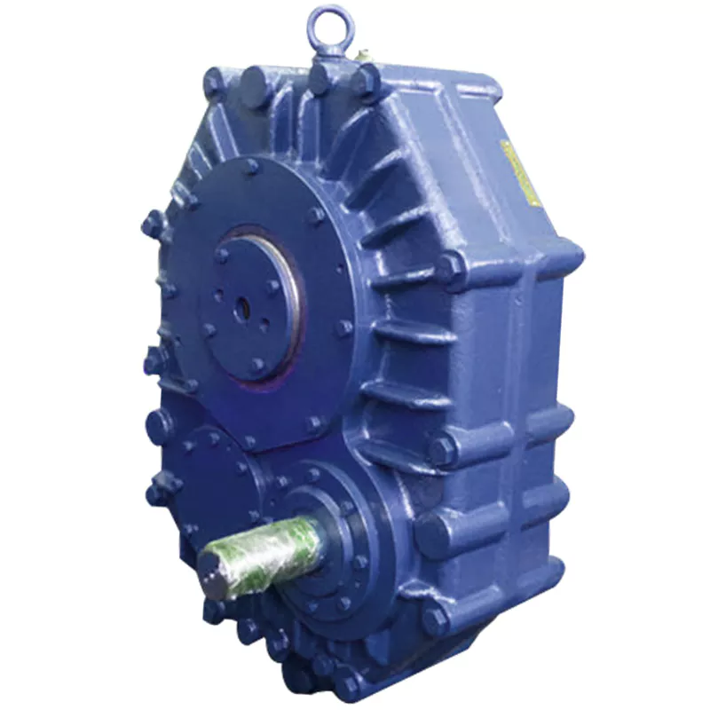
A gear reducer, also known as a gear reduction unit or gearbox, is a mechanical device designed to reduce the speed of an input shaft while increasing its torque output. It accomplishes this through the use of a set of interlocking gears with different sizes.
The primary function of a gear reducer in mechanical systems is to:
- Speed Reduction: The gear reducer takes the high-speed rotation of the input shaft and transmits it to the output shaft through a set of gears. The gears are configur
Are there any disadvantages or limitations to using gear reducer systems?
While gear reducer systems offer numerous advantages, they also come with certain disadvantages and limitations that should be considered during the selection and implementation process:
1. Size and Weight: Gear reducers can be bulky and heavy, especially for applications requiring high gear ratios. This can impact the overall size and weight of the machinery or equipment, which may be a concern in space-constrained environments.
2. Efficiency Loss: Despite their high efficiency, gear reducers can experience energy losses due to friction between gear teeth and other components. This can lead to a reduction in overall system efficiency, particularly in cases where multiple gear stages are used.
3. Cost: The design, manufacturing, and assembly of gear reducers can involve complex processes and precision machining, which can contribute to higher initial costs compared to other power transmission solutions.
4. Maintenance: Gear reducer systems require regular maintenance, including lubrication, inspection, and potential gear replacement over time. Maintenance activities can lead to downtime and associated costs in industrial settings.
5. Noise and Vibration: Gear reducers can generate noise and vibrations, especially at high speeds or when operating under heavy loads. Additional measures may be needed to mitigate noise and vibration issues.
6. Limited Gear Ratios: While gear reducers offer a wide range of gear ratios, there may be limitations in achieving extremely high or low ratios in certain designs.
7. Temperature Sensitivity: Extreme temperatures can affect the performance of gear reducer systems, particularly if inadequate lubrication or cooling is provided.
8. Shock Loads: While gear reducers are designed to handle shock loads to some extent, severe shock loads or abrupt changes in torque can still lead to potential damage or premature wear.
Despite these limitations, gear reducer systems remain widely used and versatile components in various industries, and their disadvantages can often be mitigated through proper design, selection, and maintenance practices.
ed in such a way that the output gear has a larger diameter than the input gear. As a result, the output shaft rotates at a lower speed than the input shaft, but with increased torque.
- Torque Increase: Due to the size difference between the input and output gears, the torque applied to the output shaft is greater than that of the input shaft. This torque multiplication allows the system to handle heavier loads a

What role do gear ratios play in optimizing the performance of gear reducers?
Gear ratios play a crucial role in optimizing the performance of gear reducers by determining the relationship between input and output speeds and torques. A gear ratio is the ratio of the number of teeth between two meshing gears, and it directly influences the mechanical advantage and efficiency of the gear reducer.
1. Speed and Torque Conversion: Gear ratios allow gear reducers to convert rotational speed and torque according to the needs of a specific application. By selecting appropriate gear ratios, gear reducers can either reduce speed while increasing torque (speed reduction) or increase speed while decreasing torque (speed increase).
2. Mechanical Advantage: Gear reducers leverage gear ratios to provide mechanical advantage. In speed reduction configurations, a higher gear ratio results in a greater mechanical advantage, allowing the output shaft to deliver higher torque at a lower speed. This is beneficial for applications requiring increased force or torque, such as heavy machinery or conveyor systems.
3. Efficiency: Optimal gear ratios contribute to higher efficiency in gear reducers. By distributing the load across multiple gear teeth, gear reducers with suitable gear ratios minimize stress and wear on individual gear teeth, leading to improved overall efficiency and prolonged lifespan.
4. Speed Matching: Gear ratios enable gear reducers to match the rotational speeds of input and output shafts. This is crucial in applications where precise speed synchronization is required, such as in conveyors, robotics, and manufacturing processes.
When selecting gear ratios for a gear reducer, it’s important to consider the specific requirements of the application, including desired speed, torque, efficiency, and mechanical advantage. Properly chosen gear ratios enhance the overall performance and reliability of gear reducers in a wide range of industrial and mechanical systems.
nd perform tasks requiring higher force.
Gear reducers are widely used in various industries and applications where it’s necessary to adapt the speed and torque characteristics of a power source to meet the requirements of the driven equipment. They can be found in machinery such as conveyor systems, industrial machinery, vehicles, and more.


editor by CX 2023-08-22
China high quality China Wholesale Prices Motor Speed Reducer Gear Reduction Box Servo Planetary Gearbox cycloidal gearbox applications
Product Description
Product Description
China Wholesale prices Motor Speed Reducer gear reduction box servo planetary gearbox
HangZhou Fubao Electromechanical Technology Co., Ltd. Motor Speed Reducer gear reduction box servo planetary gearbox is a new generation of practical products independently developed by our company:
Low noise: less than 65db.
Low back clearance: up to 3 arc minutes in a CZPT and 5 arc minutes in a double stage.
High torque: higher than the standard planetary reducer torque.
High stability: high strength alloy steel, the whole gear after hardening treatment, not only the surface hard substitution.
High deceleration ratio: Modular design, planetary gearbox can be interlinked.
Motor Speed Reducer gear reduction box servo planetary gearbox characteristic:
1.Planetary reducer manufacturer-Fubao Electromechanical Technology adopts an integrated planetary carrier and output shaft, which can provide better torsional rigidity. After precision machining, the gear set is not easy to eccentric, which can reduce interference, reduce wear and noise, and at the same time use a large The bearings are arranged with a wide span to distribute the load of the bearings, and once again strengthen the torque rigidity and radial load capacity of the Motor Speed Reducer gear reduction box servo planetary gearbox. The output cover is made of aluminum alloy, which provides better heat dissipation capability for the product, so that the reducer produced by Fubao Electromechanical Technology can play an excellent role in the field of mechanical tools.
2.The planetary gear set is specially made of alloy steel. First, it undergoes quenching and tempering heat treatment to make the material hardness reach HRC30 degrees, and then undergoes nitriding surface treatment to HV860, so that the product has the characteristics of high surface hardness and high toughness in the center, and achieves the best product strength and service life. optimization.
3.The input shaft and the motor output shaft are connected by a bolted structure, with a round shaft seal design, and through dynamic balance analysis, it can ensure that there is no eccentric load at high speeds. After reducing unnecessary radial force, it can effectively Reduce the load on the motor side.
4.The material of the input cover/motor connection seat is made of aluminum alloy, which can provide better heat dissipation effect, and then provide good concentricity and verticality through professional lathe processing, so that the product can be stably combined with various motors, reducing the damage caused by insufficient precision. Unnecessary axial radial force makes the product have a longer life cycle.
Product Parameters
| WVB/WVBL series parameters | Model number | WVB042/WVBL50 | WVB60/WVBL70 | WVB/WVBL90 | WVB/WVBL120 | WVB142/WVBL155 | WVB180/WVBL205 | WVB220/WVBL235 |
| Rated output torque | 13-17Nm | 32-48Nm | 80-125Nm | 165-265Nm | 280-530Nm | 480-960Nm | 900-1360Nm | |
| Reduction ratio | L1: 3, 4, 5, 7, 10 | L2: 12, 15, 20, 25, 30, 35, 40, 50, 70, 100 | ||||||
| Planetary gear backlash | L1: P1≤3 P2≤5 L2: P1≤5 P2≤7 | |||||||
Detailed Photos
Product Details
Other products
Product Advantage
Compared with other reduction machines, Motor Speed Reducer parallel shaft gearbox servo planetary gearbox machines have high rigidity, high precision (single stage can be achieved within 1 point), high transmission efficiency (single stage in 97-98%), high torque/volume ratio, lifetime maintenance free and other characteristics.
Because of these characteristics,Motor Speed Reducer parallel shaft gearbox servo planetary gearbox is mostly installed on the stepper motor and servo motor, used to reduce speed, increase torque, matching inertia.
Company Profile
HangZhou Fubao Electromechanical Technology Co., Ltd. was established in 2008, the company has a complete precision reducer design, production capacity. Set R & D, manufacturing, assembly and sales, more in the field of gear manufacturing has more than 10 years of background, in the manufacturing equipment is equipped with Switzerland Riesenhahl gear grinding machine, domestic Qinchuan gear grinding machine, hamai gear hobbing machine and domestic Xihu (West Lake) Dis. gear hobbing machine, Japan Yasaki TLGmazak CNC lathe, CNC milling machine and other fully CNC equipment, In addition, it is equipped with other advanced measuring equipment such as Japanese TTI gear detector, 3 coordinate measurement, reducer backlash measurement instrument and so on. In a strong manufacturing capacity at the same time, can be stable, continuous manufacturing of high-quality precision reducer products.
The precision reducer produced by our company has the characteristics of high structural rigidity, small back backlash, precise transmission and so on. It is widely used in various industries. Companies adhering to the concept of let customers participate in manufacturing, and strive to provide customers with more personalized services. In the field of precision transmission has a unique achievements. It is our CZPT pursuit to make far-reaching contributions.
Factory Display
Q: Speed reducer grease replacement time
A: When sealing appropriate amount of grease and running reducer, the standard replacement time is 20000 hours according to the aging condition of the grease. In addition, when the grease is stained or used in the surrounding temperature condition (above 40ºC), please check the aging and fouling of the grease, and specify the replacement time.
Q: Delivery time
A: Fubao has 2000+ production base, daily output of 1000+ units, standard models within 7 days of delivery.
Q: Reducer selection
A: Fubao provides professional product selection guidance, with higher product matching degree, higher cost performance and higher utilization rate.
Q: Application range of reducer
A: Fubao has a professional research and development team, complete category design, can match any stepping motor, servo motor, more accurate matching.
|
Shipping Cost:
Estimated freight per unit. |
To be negotiated |
|---|
| Application: | Motor, Machinery, Agricultural Machinery, Pipe Bender |
|---|---|
| Hardness: | Hardened Tooth Surface |
| Installation: | Horizontal Type |
| Customization: |
Available
| Customized Request |
|---|

The Advantages of Using a Cyclone Gearbox
Using a cycloidal gearbox to drive an input shaft is a very effective way to reduce the speed of a machine. It does this by reducing the speed of the input shaft by a predetermined ratio. It is capable of very high ratios in relatively small sizes.
Transmission ratio
Whether you’re building a marine propulsion system or a pump for the oil and gas industry, there are certain advantages to using cycloidal gearboxes. Compared to other gearbox types, they’re shorter and have better torque density. These gearboxes also offer the best weight and positioning accuracy.
The basic design of a cycloidal gearbox is similar to that of a planetary gearbox. The main difference is in the profile of the gear teeth.
Cycloid gears have less tooth flank wear and lower Hertzian contact stress. They also have lower friction and torsional stiffness. These advantages make them ideal for applications that involve heavy loads or high-speed drives. They’re also good for high gear ratios.
In a cycloidal gearbox, the input shaft drives an eccentric bearing, while the output shaft drives the cycloidal disc. The cycloidal disc rotates around a fixed ring, and the pins of the ring gear engage the holes in the disc. The pins then drive the output shaft as the disc rotates.
Cycloid gears are ideal for applications that require high gear ratios and low friction. They’re also good for applications that require high torsional stiffness and shock load resistance. They’re also suitable for applications that require a compact design and low backlash.
The transmission ratio of a cycloidal gearbox is determined by the number of lobes on the cycloidal disc. The n=n design of the cycloidal disc moves one lobe per revolution of the input shaft.
Cycloid gears can be manufactured to reduce the gear ratio from 30:1 to 300:1. These gears are suitable for high-end applications, especially in the automation industry. They also offer the best positioning accuracy and backlash. However, they require special manufacturing processes and require non-standard characteristics.
Compressive force
Compared with conventional gearboxes, the cycloidal gearbox has a unique set of kinematics. It has an eccentric bearing in a rotating frame, which drives the cycloidal disc. It is characterized by low backlash and torsional stiffness, which enables geared motion.
In this study, the effects of design parameters were investigated to develop the optimal design of a cycloidal reducer. Three main rolling nodes were studied: a cycloidal disc, an outer race and the input shaft. These were used to analyze the motion related dynamic forces, which can be used to calculate stresses and strains. The gear mesh frequency was calculated using a formula, which incorporated a correction factor for the rotating frame of the outer race.
A three-dimensional finite element analysis (FEA) study was conducted to evaluate the cycloidal disc. The effects of the size of the holes on the disc’s induced stresses were investigated. The study also looked at the torque ripple of a cycloidal drive.
The authors of this study also explored backlash distribution in the output mechanism, which took into account the machining deviations and structure and geometry of the output mechanism. The study also looked at the relative efficiency of a cycloidal reducer, which was based on a single disc cycloidal reducer with a one-tooth difference.
The authors of this study were able to deduce the contact stress of the cycloidal disc, which is calculated using the material-based contact stiffness. This can be used to determine accurate contact stresses in a cycloidal gearbox.
It is important to know the ratios needed for calculation of the bearing rate. This can be calculated using the formula f = k (S x R) where S is the volume of the element, R is the mass, k is the contact stiffness and f is the force vector.
Rotational direction
Unlike the conventional ring gear which has a single axis of rotation, cycloidal gearbox has three rotational axes which are parallel and are located in a single plane. A cycloidal gearbox has excellent torsional stiffness and shock load capacity. It also ensures constant angular velocity, and is used in high-speed gearbox applications.
A cycloidal gearbox consists of an input shaft, a drive member and a cycloidal disc. The disc rotates in one direction, while the input shaft rotates in the opposite direction. The input shaft eccentrically mounts to the drive member. The cycloidal disc meshes with the ring-gear housing, and the rotational motion of the cycloidal disc is transferred to the output shaft.
To calculate the rotational direction of a cycloidal gearbox, the cycloid must have the correct angular orientation and the centerline of the cycloid should be aligned with the center of the output hole. The cycloid’s shortest length should be equal to the radius of the pin circle. The cycloid’s largest radius should be the size of the bearing’s exterior diameter.
A single-stage gear will not have much space to work with, so you’ll need a multistage gear to maximize space. This is also the reason that cycloid gears are usually designed with a shortened cycloid.
To calculate the most efficient tooth profile for a cycloidal gear, a new method was devised. This method uses a mathematical model that uses the cycloid’s rotational direction and a few other geometric parameters. Using a piecewise function related to the distribution of pressure angle, the cycloid’s most efficient profile is determined. It is then superimposed on the theoretical profile. The new method is much more flexible than the conventional method, and can adapt to changing trends of the cycloidal profile.
Design
Several designs of cycloidal gearboxes have been developed. These gearboxes have a large reduction ratio in one stage. They are mainly used for heavy machines. They provide good torsional stiffness and shock load capacity. However, they also have vibrations at high RPM. Several studies have been conducted to find a solution to this problem.
A cycloidal gearbox is designed by calculating the reduction ratio of a mechanism. This ratio is obtained by the size of the input speed. This is then multiplied by the reduction ratio of the gear profile.
The most important factor in the design of a cycloidal gearbox is the load distribution along the width of the gear. Using this as a design criterion, the amplitude of vibration can be reduced. This will ensure that the gearbox is working properly. In order to generate proper mating conditions, the trochoidal profile on the cycloidal disc periphery must be defined accurately.
One of the most common forms of cycloidal gears is circular arc toothing. This is the most common type of toothing used today.
Another form of gear is the hypocycloid. This form requires the rolling circle diameter to be equal to half the base circle diameter. Another special case is the point tooth form. This form is also called clock toothing.
In order to make this gear profile work, the initial point of contact must remain fixed to the edge of the rolling disk. This will generate the hypocycloid curve. The curve is traced from this initial point.
To investigate this gear profile, the authors used a 3D finite element analysis. They used the mathematical model of gear manufacturing that included kinematics parameters, output moment calculations, and machining steps. The resulting design eliminated backlash.
Sizing and selection
Choosing a gearbox can be a complex task. There are many factors that need to be taken into account. You need to determine the type of application, the required speed, the load, and the ratio of the gearbox. By gaining this information, you can find a solution that works best for you.
The first thing you need to do is find the proper size. There are several sizing programs available to help you determine the best gearbox for your application. You can start by drawing a cycloidal gear to help you create the part.
During sizing, it is important to consider the environment. Shock loads, environmental conditions, and ambient temperatures can increase wear on the gear teeth. The temperature also has a significant impact on lubrication viscosities and seal materials.
You also need to consider the input and output speed. This is because the input speed will change your gearbox ratio calculations. If you exceed the input speed, you can damage the seals and cause premature wear on the shaft bearings.
Another important aspect of sizing is the service factor. This factor determines the amount of torque the gearbox can handle. The service factor can be as low as 1.4, which is sufficient for most industrial applications. However, high shock loads and impact loads will require higher service factors. Failure to account for these factors can lead to broken shafts and damaged bearings.
The output style is also important. You need to determine if you want a keyless or keyed hollow bore, as well as if you need an output flange. If you choose a keyless hollow bore, you will need to select a seal material that can withstand the higher temperatures.

editor by CX 2023-05-29
China Custom Helical Bevel Gearbox Helical Couping Helical Gear Box cycloidal gear reducer design
Product Description
Features
1.Wide transmission rate, strong output torque
2.Compact mechanical structure, light weight, small volume&Good heat-dissipating
3.Smooth operation with lower noise or vibration
4.Easy mounting, free linking, high efficiency
5.Upto 96% transmission efficiency
5. PERFECT SUBSTITUDE FOR SEW AND TRANSTECNO PRODUCTS
Applications
Wide range of application,including light industry of food &beverage, Cement,
package,construction material,chemicals and etc.
Technical data:
| Model | SRC01, SRC02, SRC03, SRC04 |
| Single unit versions | SRC-P IEC motor mounting SRC-HS shaft mounting |
| Power | 0.25—-4KW |
| reduction ratio | 3.66 – 54 |
| Output torque | 3.0—500N.M |
| Gear material | 20CrMnTi with carburizing and quenching.The hardness of surface is 56-62HRC with carbonized layer 0.5-0.8mm |
After-sale service:
One year warranty,subject to proper operation and installation;free technical support all the time.
|
Shipping Cost:
Estimated freight per unit. |
To be negotiated|
|
|---|
| Application: | Motor |
|---|---|
| Layout: | Cycloidal |
| Hardness: | Hardened Tooth Surface |
| Customization: |
Available
| Customized Request |
|---|
Condition Monitoring of Cyclone Gearboxes
Whether you’re considering using a cycloidal gearbox in your home, office, or garage, you’ll want to make sure it’s made of quality material. You also want to make sure it’s designed properly, so it won’t be damaged by vibrations.
Planetary gearboxes
Compared to cycloidal gearboxes, planetary gearboxes are lighter and more compact, but they lack the precision and durability of the former. They are better suited for applications with high torque or speed requirements. For this reason, they are usually used in robotics applications. But, cycloidal gearboxes are still better for some applications, including those involving shock loads.
There are many factors that affect the performance of gearboxes during production. One of these is the number of teeth. In the case of planetary gearboxes, the number of teeth increases with the number of planets. The number of teeth is reduced in cycloidal gearboxes, which results in higher transmission ratios. These gearboxes also have lower breakaway torques, which means that they can be controlled more easily by the user.
A cycloid gearbox is comprised of three main parts: the ring gear, the sun gear, and the input shaft. The ring gear is fixed in the gearbox, while the sun gear transmits the rotation to the planet gears. The input shaft transfers motion to the sun gear, which in turn transmits it to the output shaft. The output shaft has a larger torque than the input shaft.
Cycloid gears have better torsional stiffness, lower wear, and lower Hertzian contact stress. However, they are also larger in size and require highly accurate manufacturing. Cycloid gears can be more difficult to manufacture than involute gears, which require large amounts of precision.
Cycloid gears can offer transmission ratios up to 300:1, and they can do this in a small package. They also have lower wear and friction, which makes them ideal for applications that require a high transmission ratio.
Cycloid gearboxes are usually equipped with a backlash of about one angular minute. This backlash provides the precision and control necessary for accurate movement. They also provide low wear and shock load capacity.
Planetary gearboxes are available in single and two-stage designs, which increase in length as stages are added. In addition to the two stages, they can be equipped with an optional output bearing, which takes up mounting space. In some applications, a third stage is also available.
Involute gears
Generally, involute gears are more complex to manufacture than cycloidal gears. For example, an involute gear tooth profile has a single curve while a cycloidal gear tooth profile has two curves. In addition, the involute curve is not within the base circle.
The involute curve is a very important component of a gear tooth and it can significantly influence the quality of contact meshing between teeth. Various works have been done on the subject, mainly focusing on the operating principles. In addition, the most important characteristic of the double-enveloping cycloid drive is its double contact lines between the meshing tooth pairs.
Cycloid gears are more powerful, less noisy, and last longer than involute gears. They also require less manufacturing operations during production. However, cycloid gears are more expensive than involute gears. Involute gears are more commonly used in linear motions while cycloid gears are used for rotary motions.
Although cycloid gears are more technically advanced, involute gears have the superior quality and are more aesthetically pleasing. Cycloid gears are used in various industrial applications such as pumps and compressors. They are also widely used in the watch industry. Nevertheless, involute gears have not yet replaced cycloid gears in the watch industry.
The cycloid disc has a number of pins around its outer edge, while an involute gear has only a single curve for the teeth. In addition, cycloid gears have a more robust and reliable design. Involute gears, on the other hand, have a cheaper rack cutter and less expensive involute teeth.
The cycloid disc’s transmission accuracy is about 98.5%, while the ring gear’s transmission accuracy is about 96%. The cycloid disc’s rotational velocity has a magnitude of 3 rad/s. A small change in the center distance does not affect the transmission accuracy. However, rotational velocity fluctuation can affect the transmission accuracy.
Cycloid gears also have the cycloid gear disc’s rotational velocity. The disc has N lobes. However, the cycloid gear disc’s transmission accuracy is still not perfect. This is because of the large rotational angles between the lobes. This also makes it difficult to manufacture.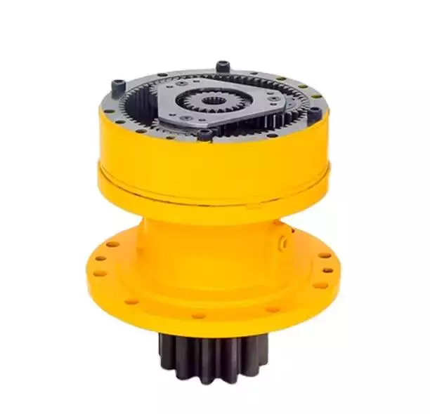
Vibrations
Using modern techniques for vibration diagnostics and data-driven methods, this article presents a new approach to condition monitoring of cycloidal gearboxes. This approach focuses on detecting the root cause of gearbox failure. The article aims to provide a unified approach to gear designers.
A cycloidal gearbox is a high-precision gearbox that is used in heavy-duty machines. It has a large reduction ratio, which makes it necessary to have a very large input speed. Cycloid gears have high accuracy, but they are susceptible to vibration issues. In this article, the authors describe how a cycloidal gearbox works and how vibrations are measured. They also show how this gearbox can be used to detect faults.
The gearbox is used in positioners, multi-axis robots, and heavy-duty machines. The main characteristics of this gearbox are the high accuracy, the overload capacity, and the large reduction ratio.
There is little documentation on vibrations and condition monitoring of cycloidal gearboxes. The authors describe their approach to the problem, using a cycloidal gearbox and a testing bench. Their approach involves measuring the frequency of the gearbox with different input speeds.
The results show a good separation between the healthy and damaged states. Fault frequencies show up in the lower orders of frequencies. Faults can be detected using binning, which eliminates the need for a tachometer. In addition, binning is combined with Principal Component Analysis to determine the state of the gearbox.
This method is compared to traditional techniques. In addition, the results show how binning can be used to calculate the defect frequencies of the bearings. It is also used to determine the frequencies of the components.
The signals from the test bench are acquired using four sensors. These sensors are medium sensitivity 100 mV/g accelerometers. The signals are then processed using different signal processing techniques. The results show that the vibration signals are correlated with the internal motion of the gearbox. This information is used to identify the internal frequency of the transmission.
The frequency analysis of vibration signals is performed in cyclostationary and noncyclostationary conditions. The signals are then analyzed to determine the magnitude of the gear meshing frequency.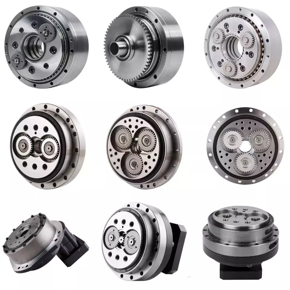
Design
Using precision gearboxes, servomotors can now control heavy loads at high speed. Unlike cam indexing devices, cycloidal gears provide extremely accurate positioning and high torque. They also provide excellent torsional stiffness and shock load capacity.
Cycloid gears are specially designed to minimize vibration at high RPM. Unlike involute gears, they are not stacked, which reduces friction and forces experienced by each tooth. In addition, cycloidal gears have lower Hertzian contact stress.
Cycloid gears are often used in multi-axis robots for positioners. They can provide transmission ratios as high as 300:1 in a compact package. They are also used in first joints in heavy machines. However, they require extremely accurate manufacturing. They are also more difficult to produce than involute gears.
A cycloidal gearbox is a type of planetary gearbox. Cycloid gears are specially designed for high gear ratios. They also have the ability to provide a large reduction ratio in a single stage. They are increasingly used in first joints in heavy machines. They are also becoming more common in robotics.
In order to achieve a large reduction ratio, the input speed of the gear must be very high. Generally, the input speed is between 500 rpm and 4500 rpm. However, in some cases, the input speed may be lower.
A cycloid is formed by rolling a rolling circle on a base circle. The ratio between the rolling circle diameter and the base circle diameter determines the shape of the cycloid. A hypocycloid is formed by rolling primarily on the inside of the base circle, while an epicycloid is formed by rolling primarily on the outside of the base circle.
Cycloid gears have a very small backlash, which minimizes the forces experienced by each tooth. These gears also have a good torsional stiffness, low friction, and shock load capacity. They also provide the best positioning accuracy.
The cycloidal gearbox was designed and built at Radom University. The design was based on three different cycloidal gears. The first pair had the external profile at the nominal dimension, while the second pair had the profile minus tolerance. The load plate had threaded screw holes arranged 15 mm away from the center.

editor by CX 2023-05-12
China wholesaler Factory Gpb090 Gvb CZPT Gear Box Transmission Gearbox Robtic Arm Planetary Gearhead cycloidal drive purpose
Product Description
TaiBang Motor Industry Group Co., Ltd.
The main products is induction motor, reversible motor, DC brush gear motor, DC brushless gear motor, CH/CV big gear motors, Planetary gear motor ,Worm gear motor etc, which used widely in various fields of manufacturing pipelining, transportation, food, medicine, printing, fabric, packing, office, apparatus, entertainment etc, and is the preferred and matched product for automatic machine.
Model Instruction
GB090-10-P2
| GB | 090 | 571 | P2 |
| Reducer Series Code | External Diameter | Reduction Ratio | Reducer Backlash |
| GB:High Precision Square Flange Output
GBR:High Precision Right Angle Square Flange Output GE:High Precision Round Flange Output GER:High Precision Right Round Flange Output |
050:ø50mm 070:ø70mm 090:ø90mm 120:ø120mm 155:ø155mm 205:ø205mm 235:ø235mm 042:42x42mm 060:60x60mm 090:90x90mm 115:115x115mm 142:142x142mm 180:180x180mm 220:220x220mm |
571 means 1:10 | P0:High Precision Backlash
P1:Precison Backlash P2:Standard Backlash |
Main Technical Performance
| Item | Number of stage | Reduction Ratio | GB042 | GB060 | GB060A | GB090 | GB090A | GB115 | GB142 | GB180 | GB220 |
| Rotary Inertia | 1 | 3 | 0.03 | 0.16 | 0.61 | 3.25 | 9.21 | 28.98 | 69.61 | ||
| 4 | 0.03 | 0.14 | 0.48 | 2.74 | 7.54 | 23.67 | 54.37 | ||||
| 5 | 0.03 | 0.13 | 0.47 | 2.71 | 7.42 | 23.29 | 53.27 | ||||
| 6 | 0.03 | 0.13 | 0.45 | 2.65 | 7.25 | 22.75 | 51.72 | ||||
| 7 | 0.03 | 0.13 | 0.45 | 2.62 | 7.14 | 22.48 | 50.97 | ||||
| 8 | 0.03 | 0.13 | 0.44 | 2.58 | 7.07 | 22.59 | 50.84 | ||||
| 9 | 0.03 | 0.13 | 0.44 | 2.57 | 7.04 | 22.53 | 50.63 | ||||
| 10 | 0.03 | 0.13 | 0.44 | 2.57 | 7.03 | 22.51 | 50.56 | ||||
| 2 | 15 | 0.03 | 0.03 | 0.13 | 0.13 | 0.47 | 0.47 | 2.71 | 7.42 | 23.29 | |
| 20 | 0.03 | 0.03 | 0.13 | 0.13 | 0.47 | 0.47 | 2.71 | 7.42 | 23.29 | ||
| 25 | 0.03 | 0.03 | 0.13 | 0.13 | 0.47 | 0.47 | 2.71 | 7.42 | 23.29 | ||
| 30 | 0.03 | 0.03 | 0.13 | 0.13 | 0.47 | 0.47 | 2.71 | 7.42 | 23.29 | ||
| 35 | 0.03 | 0.03 | 0.13 | 0.13 | 0.47 | 0.47 | 2.71 | 7.42 | 23.29 | ||
| 40 | 0.03 | 0.03 | 0.13 | 0.13 | 0.47 | 0.47 | 2.71 | 7.42 | 23.29 | ||
| 45 | 0.03 | 0.03 | 0.13 | 0.13 | 0.47 | 0.47 | 2.71 | 7.42 | 23.29 | ||
| 50 | 0.03 | 0.03 | 0.13 | 0.13 | 0.44 | 0.44 | 2.57 | 7.03 | 22.51 | ||
| 60 | 0.03 | 0.03 | 0.13 | 0.13 | 0.44 | 0.44 | 2.57 | 7.03 | 22.51 | ||
| 70 | 0.03 | 0.03 | 0.13 | 0.13 | 0.44 | 0.44 | 2.57 | 7.03 | 22.51 | ||
| 80 | 0.03 | 0.03 | 0.13 | 0.13 | 0.44 | 0.44 | 2.57 | 7.03 | 22.51 | ||
| 90 | 0.03 | 0.03 | 0.13 | 0.13 | 0.44 | 0.44 | 2.57 | 7.03 | 22.51 | ||
| 100 | 0.03 | 0.03 | 0.13 | 0.13 | 0.44 | 0.44 | 2.57 | 7.03 | 22.51 |
| Item | Number of stage | GB042 | GB060 | GB060A | GB90 | GB090A | GB115 | GB142 | GB180 | GB220 | |
| Backlash(arcmin) | High Precision P0 | 1 | ≤1 | ≤1 | ≤1 | ≤1 | ≤1 | ≤1 | |||
| 2 | ≤3 | ≤3 | ≤3 | ≤3 | |||||||
| Precision P1 | 1 | ≤3 | ≤3 | ≤3 | ≤3 | ≤3 | ≤3 | ≤3 | ≤3 | ≤3 | |
| 2 | ≤5 | ≤5 | ≤5 | ≤5 | ≤5 | ≤5 | ≤5 | ≤5 | ≤5 | ||
| Standard P2 | 1 | ≤5 | ≤5 | ≤5 | ≤5 | ≤5 | ≤5 | ≤5 | ≤5 | ≤5 | |
| 2 | ≤7 | ≤7 | ≤7 | ≤7 | ≤7 | ≤7 | ≤7 | ≤7 | ≤7 | ||
| Torsional Rigidity(N.M/arcmin) | 1 | 3 | 7 | 7 | 14 | 14 | 25 | 50 | 145 | 225 | |
| 2 | 3 | 7 | 7 | 14 | 14 | 25 | 50 | 145 | 225 | ||
| Noise(dB) | 1,2 | ≤56 | ≤58 | ≤58 | ≤60 | ≤60 | ≤63 | ≤65 | ≤67 | ≤70 | |
| Rated input speed(rpm) | 1,2 | 5000 | 5000 | 5000 | 4000 | 4000 | 4000 | 3000 | 3000 | 2000 | |
| Max input speed(rpm) | 1,2 | 10000 | 10000 | 10000 | 8000 | 8000 | 8000 | 6000 | 6000 | 4000 | |
Noise test standard:Distance 1m,no load.Measured with an input speed 3000rpm
| Application: | Machinery, Agricultural Machinery |
|---|---|
| Function: | Distribution Power, Change Drive Torque, Change Drive Direction, Speed Reduction |
| Layout: | Cycloidal |
| Hardness: | Hardened Tooth Surface |
| Installation: | Vertical Type |
| Step: | Double-Step |
| Samples: |
US$ 50/Piece
1 Piece(Min.Order) | |
|---|
| Customization: |
Available
| Customized Request |
|---|
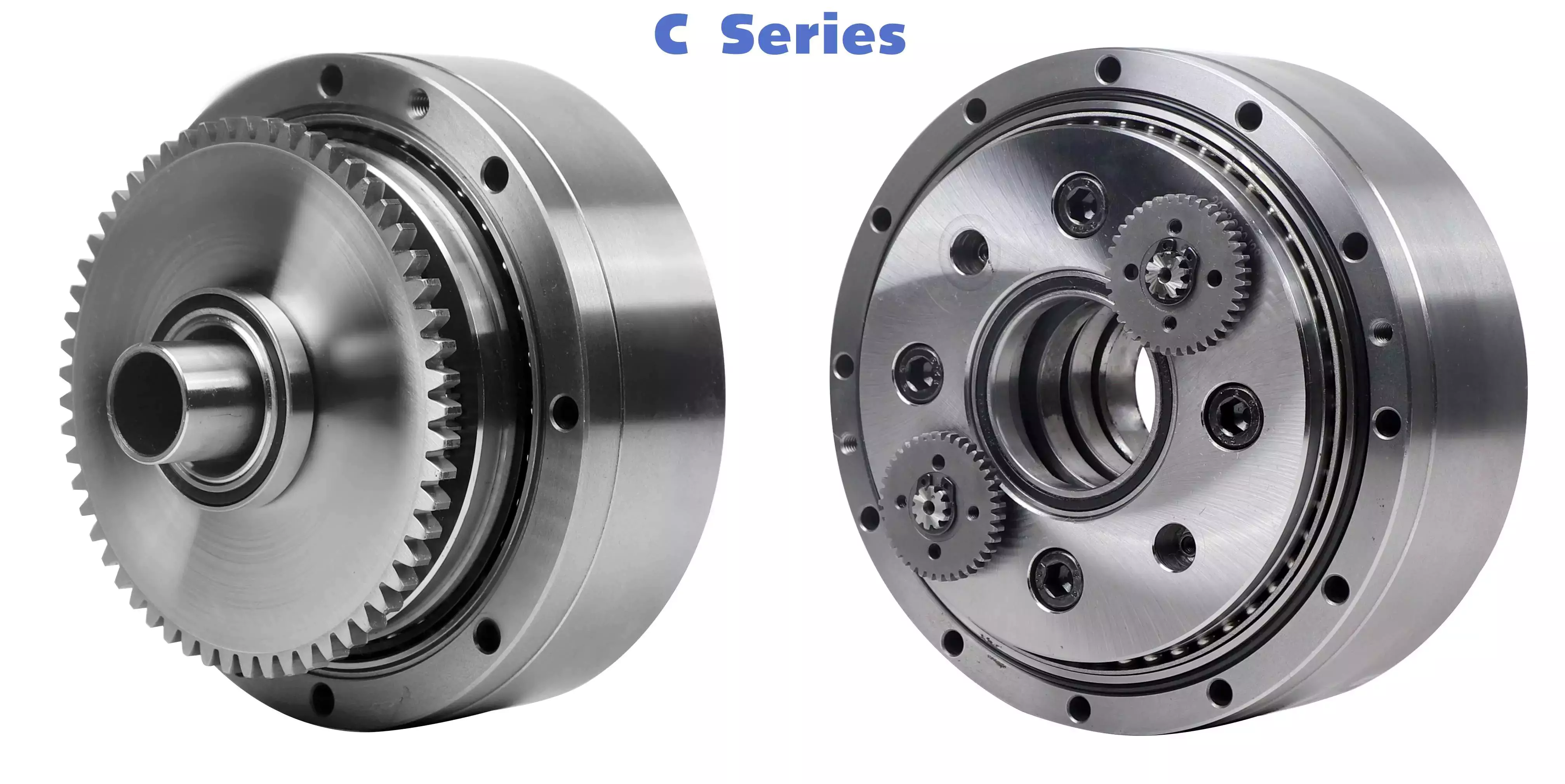
The Basics of a Cyclone Gearbox
Besides being compact, cycloidal speed reducers also offer low backlash and high ratios. Because of the small size of the drive, they are ideal for applications where space is a problem.
Involute gear tooth profile
Almost all gears use an involute gear tooth profile. This profile has a single curve, which means that the gear teeth do not have to be aligned closely with each other. This profile is smooth and can be manufactured easily.
Cycloid gears have a combination of epicycloid and hypocycloid curves. This makes them stronger than involute gear teeth. However, they can be more expensive to manufacture. They also have larger reduction ratios. They transmit more power than involute gears. Cycloid gears can be found in clocks.
When designing a gear, you need to consider several factors. Some of these include the number of teeth, the tooth angle and the lubrication type. Having a gear tooth that is not perfectly aligned can result in transmission error, noise and vibration.
The tooth profile of an involute gear is usually considered the best. Because of this, it is used in a wide variety of gears. Some of the most common applications for this profile are power transmission gears. However, this profile is not the best for every application.
Cycloid gears require more complex manufacturing processes than involute gear teeth. This can cause a larger tooth cost. Cycloid gears are used for less noisy applications.
Cycloid gears also transmit more power than involute gears. This can cause problems if the radii change tangentially. However, the shape is more simple than involute gears. Involute gears can handle centre sifts better.
Cycloid gears are less susceptible to transmission error. Cycloid gears have a convex surface, which makes them stronger than involute teeth. Cycloid gears also have a larger reduction ratio than involute gears. Cycloid teeth do not interfere with the mating teeth. However, they have a smaller number of teeth than involute teeth.
Rotation on the inside of the reference pitch circle of the pins
Whether a cycloidal gearbox is designed for stationary or rotating applications, the fundamental law of gearing must be observed: The ratio of angular velocities must be constant. This requires the rotation on the inside of the reference pitch circle of the pins to be constant. This is achieved through a series of cycloidal teeth, which act like tiny levers to transmit motion.
A cycloidal disc has N lobes which are rotated by three lobes per rotation around N pins. The number of lobes on a cycloidal disc is a significant factor in determining the transmission ratio.
A cycloidal disc is driven by an eccentric input shaft which is mounted to an eccentric bearing within an output shaft. As the input shaft rotates, the cycloidal disc moves around the pins of the pin disc.
The drive pin rotates at a 40 deg angle while the cycloidal disc rotates on the inside of the reference pitch circle of pins. As the drive pin rotates, it will slow the output motion. This means that the output shaft will complete only three revolutions with the input shaft, as opposed to nine revolutions with the input shaft.
The number of teeth on a cycloidal disc must be small compared to the number of surrounding pins. The disc must also be constructed with an eccentric radius. This will determine the size of the hole which will be required for the pin to fit between the pins.
When the input shaft is turned, the cycloidal disc will rotate on the inside of the reference pitch circle of roller pins. This will then transmit motion to the output shaft. The output shaft is supported by two bearings in an output housing. This design has low wear and torsional stiffness.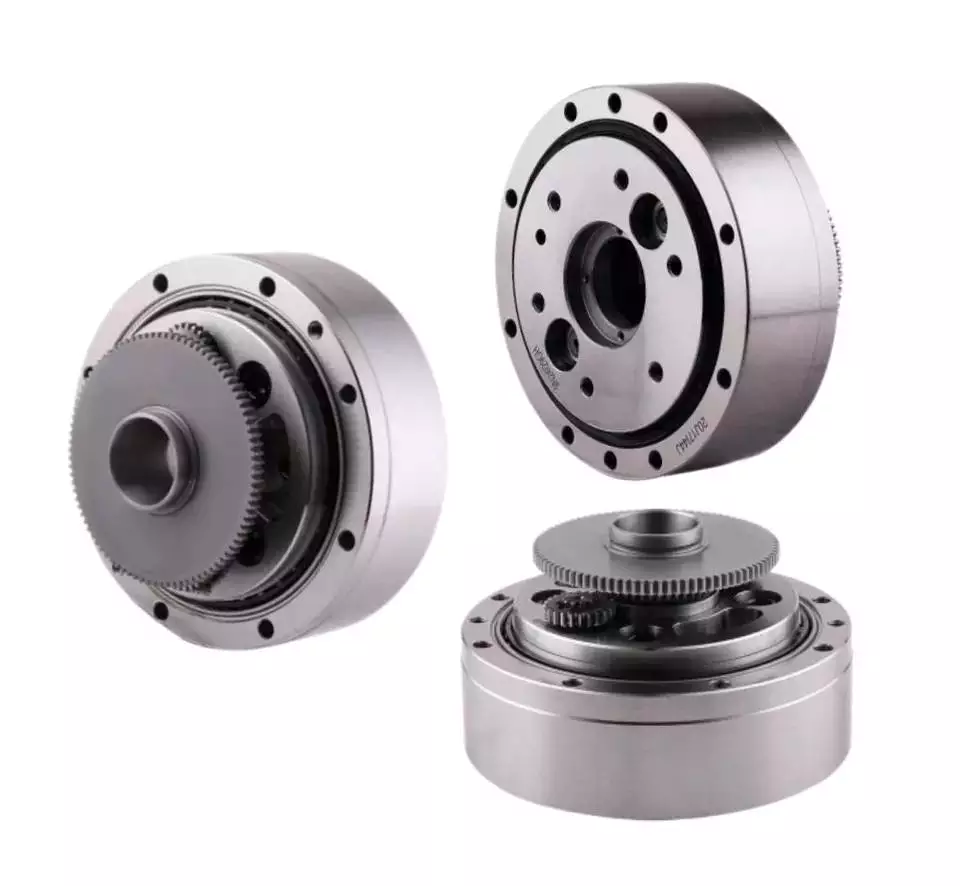
Transmission ratio
Choosing the right transmission ratio of cycloidal gearbox isn’t always easy. You might need to know the size of your gearbox before you can make an educated choice. You may also need to refer to the product catalog for guidance. For example, CZPT gearboxes have some unique ratios.
A cycloidal gear reducer is a compact and high-speed torque transmission device that reverses the direction of angular movement of the follower shaft. It consists of an eccentric cam positioned inside a cycloidal disc. Pin rollers on the follower shaft fit into matching holes in the cycloidal disc. In the process, the pins slide around the holes, in response to wobbling motion. The cycloidal disc is also capable of engaging the internal teeth of a ring-gear housing.
A cycloidal gear reducer can be used in a wide variety of applications, including industrial automation, robotics and power transmissions on boats and cranes. A cycloidal gear reducer is ideally suited for heavy duty applications with large payloads. They require specialized manufacturing processes, and are often used in equipment with precise output and high efficiency.
The cycloidal gear reducer is a relatively simple structure, but it does require some special tools. Cycloid gear reducers are also used to transmit torque, which is one of the reasons they are so popular in automation. Using a cycloidal gear reducer is a good choice for applications that require higher efficiency and lower backlash. It is also a good choice for applications where size is a concern. Cycloid gears are also a good choice for applications where high speed and high torque are required.
The transmission ratio of cycloidal gearbox is probably the most important function of a gearbox. You need to know the size of your gearbox and the type of gears it contains in order to make the right choice.
Vibration reduction
Considering the unique dynamics of a cycloidal gearbox, vibration reduction measures are required for a smooth operation. These measures can also help with the detection of faults.
A cycloidal gearbox is a gearbox with an eccentric bearing that rotates the center of the gears. It shares torque load with five outer rollers at any given time. It can be applied in many applications. It is a relatively inexpensive asset. However, if it fails, it can have significant economic impacts.
A typical input/output gearbox consists of a ring plate and two cranks mounted on the input shaft. The ring plate rotates when the input shaft rotates. There are two bearings on the output shaft.
The ring plate is a major noise source because it is not balanced. The cycloidal gear also produces noise when it meshes with the ring plate. This noise is generated by structural resonance. Several studies have been performed to solve this problem.
However, there is not much documented work on the condition monitoring of cycloidal gearboxes. In this article, we will introduce modern techniques for vibration diagnostics.
A cycloidal gearbox with a reduced reduction ratio has higher induced stresses in the cycloidal disc. In this case, the size of the output hole is larger and more material is removed from the cycloidal disc. This increase in the disc’s stresses leads to higher vibration amplitudes.
The load distribution along the width of the gear is an important design criterion. Using different gear profiles can help to optimize the transmission of torque. The contact stress of the cycloidal disc can also be investigated.
To determine the amplitude of the noise, the frequency of the gear mesh is multiplied by the shaft rate. If the RPM is relatively stable, the frequency can be used as a measure of magnitude. However, this is only accurate at close to failure.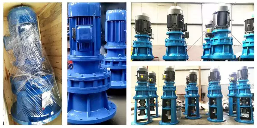
Comparison with planetary gearboxes
Several differences exist between cycloidal gearboxes and planetary gearboxes. They are related to gear geometry and manufacturing processes. Among them, there are:
– The output shaft of a cycloidal gearbox has a larger torque than the input shaft. The rotational speed of the output shaft is lower than the input shaft.
– The cycloid gear disc rotates at variable velocity, while the planetary gear has a fixed speed. Consequently, the cycloid disc and output flange transmission accuracy is lower than that of the planetary gears.
– The cycloidal gearbox has a larger gripping area than the planetary gear. This is an advantage of the cycloidal gearbox in that it can handle larger loads.
– The cycloid profile has a significant impact on the quality of contact meshing between the tooth surfaces. The width of the contact ellipses increases by 90%. This is a result of the elimination of undercuts of the lobes. In this way, the contact force on the cycloid disc is decreased significantly.
– The cycloid drive has lower backlash and high torsional stiffness. This allows a cycloidal drive to be more stable against shock loads. The cycloid drive is also a compact design, which is ideally suited for applications with large transmission ratios.
– The output hub of the cycloid gearbox has movable pins and rollers. These components are attached to the ring gear in the outer gearbox. The output shaft is also turned by the planet carrier. The output hub of the cycloid system is composed of two parts: the ring gear and the output flange.
– The input shaft of a cycloidal gearbox is connected to a servomotor. The input shaft is a cylindrical element that is fixed to the planet carrier.

editor by CX 2023-04-26
China Best Sales CZPT Gpb Transmission Gearbox Reducer Planetary Right Angle Gear Box Gearhead Manufacture cycloidal drive principle
Product Description
TaiBang Motor Industry Group Co., Ltd.
The main products is induction motor, reversible motor, DC brush gear motor, DC brushless gear motor, CH/CV big gear motors, Planetary gear motor ,Worm gear motor etc, which used widely in various fields of manufacturing pipelining, transportation, food, medicine, printing, fabric, packing, office, apparatus, entertainment etc, and is the preferred and matched product for automatic machine.
Model Instruction
GB090-10-P2
| GB | 090 | 571 | P2 |
| Reducer Series Code | External Diameter | Reduction Ratio | Reducer Backlash |
| GB:High Precision Square Flange Output
GBR:High Precision Right Angle Square Flange Output GE:High Precision Round Flange Output GER:High Precision Right Round Flange Output |
050:ø50mm 070:ø70mm 090:ø90mm 120:ø120mm 155:ø155mm 205:ø205mm 235:ø235mm 042:42x42mm 060:60x60mm 090:90x90mm 115:115x115mm 142:142x142mm 180:180x180mm 220:220x220mm |
571 means 1:10 | P0:High Precision Backlash
P1:Precison Backlash P2:Standard Backlash |
Main Technical Performance
| Item | Number of stage | Reduction Ratio | GB042 | GB060 | GB060A | GB090 | GB090A | GB115 | GB142 | GB180 | GB220 |
| Rotary Inertia | 1 | 3 | 0.03 | 0.16 | 0.61 | 3.25 | 9.21 | 28.98 | 69.61 | ||
| 4 | 0.03 | 0.14 | 0.48 | 2.74 | 7.54 | 23.67 | 54.37 | ||||
| 5 | 0.03 | 0.13 | 0.47 | 2.71 | 7.42 | 23.29 | 53.27 | ||||
| 6 | 0.03 | 0.13 | 0.45 | 2.65 | 7.25 | 22.75 | 51.72 | ||||
| 7 | 0.03 | 0.13 | 0.45 | 2.62 | 7.14 | 22.48 | 50.97 | ||||
| 8 | 0.03 | 0.13 | 0.44 | 2.58 | 7.07 | 22.59 | 50.84 | ||||
| 9 | 0.03 | 0.13 | 0.44 | 2.57 | 7.04 | 22.53 | 50.63 | ||||
| 10 | 0.03 | 0.13 | 0.44 | 2.57 | 7.03 | 22.51 | 50.56 | ||||
| 2 | 15 | 0.03 | 0.03 | 0.13 | 0.13 | 0.47 | 0.47 | 2.71 | 7.42 | 23.29 | |
| 20 | 0.03 | 0.03 | 0.13 | 0.13 | 0.47 | 0.47 | 2.71 | 7.42 | 23.29 | ||
| 25 | 0.03 | 0.03 | 0.13 | 0.13 | 0.47 | 0.47 | 2.71 | 7.42 | 23.29 | ||
| 30 | 0.03 | 0.03 | 0.13 | 0.13 | 0.47 | 0.47 | 2.71 | 7.42 | 23.29 | ||
| 35 | 0.03 | 0.03 | 0.13 | 0.13 | 0.47 | 0.47 | 2.71 | 7.42 | 23.29 | ||
| 40 | 0.03 | 0.03 | 0.13 | 0.13 | 0.47 | 0.47 | 2.71 | 7.42 | 23.29 | ||
| 45 | 0.03 | 0.03 | 0.13 | 0.13 | 0.47 | 0.47 | 2.71 | 7.42 | 23.29 | ||
| 50 | 0.03 | 0.03 | 0.13 | 0.13 | 0.44 | 0.44 | 2.57 | 7.03 | 22.51 | ||
| 60 | 0.03 | 0.03 | 0.13 | 0.13 | 0.44 | 0.44 | 2.57 | 7.03 | 22.51 | ||
| 70 | 0.03 | 0.03 | 0.13 | 0.13 | 0.44 | 0.44 | 2.57 | 7.03 | 22.51 | ||
| 80 | 0.03 | 0.03 | 0.13 | 0.13 | 0.44 | 0.44 | 2.57 | 7.03 | 22.51 | ||
| 90 | 0.03 | 0.03 | 0.13 | 0.13 | 0.44 | 0.44 | 2.57 | 7.03 | 22.51 | ||
| 100 | 0.03 | 0.03 | 0.13 | 0.13 | 0.44 | 0.44 | 2.57 | 7.03 | 22.51 |
| Item | Number of stage | GB042 | GB060 | GB060A | GB90 | GB090A | GB115 | GB142 | GB180 | GB220 | |
| Backlash(arcmin) | High Precision P0 | 1 | ≤1 | ≤1 | ≤1 | ≤1 | ≤1 | ≤1 | |||
| 2 | ≤3 | ≤3 | ≤3 | ≤3 | |||||||
| Precision P1 | 1 | ≤3 | ≤3 | ≤3 | ≤3 | ≤3 | ≤3 | ≤3 | ≤3 | ≤3 | |
| 2 | ≤5 | ≤5 | ≤5 | ≤5 | ≤5 | ≤5 | ≤5 | ≤5 | ≤5 | ||
| Standard P2 | 1 | ≤5 | ≤5 | ≤5 | ≤5 | ≤5 | ≤5 | ≤5 | ≤5 | ≤5 | |
| 2 | ≤7 | ≤7 | ≤7 | ≤7 | ≤7 | ≤7 | ≤7 | ≤7 | ≤7 | ||
| Torsional Rigidity(N.M/arcmin) | 1 | 3 | 7 | 7 | 14 | 14 | 25 | 50 | 145 | 225 | |
| 2 | 3 | 7 | 7 | 14 | 14 | 25 | 50 | 145 | 225 | ||
| Noise(dB) | 1,2 | ≤56 | ≤58 | ≤58 | ≤60 | ≤60 | ≤63 | ≤65 | ≤67 | ≤70 | |
| Rated input speed(rpm) | 1,2 | 5000 | 5000 | 5000 | 4000 | 4000 | 4000 | 3000 | 3000 | 2000 | |
| Max input speed(rpm) | 1,2 | 10000 | 10000 | 10000 | 8000 | 8000 | 8000 | 6000 | 6000 | 4000 | |
Noise test standard:Distance 1m,no load.Measured with an input speed 3000rpm
| Application: | Machinery, Agricultural Machinery |
|---|---|
| Function: | Distribution Power, Change Drive Torque, Change Drive Direction, Speed Reduction |
| Layout: | Cycloidal |
| Hardness: | Hardened Tooth Surface |
| Installation: | Vertical Type |
| Step: | Double-Step |
| Samples: |
US$ 50/Piece
1 Piece(Min.Order) | |
|---|
| Customization: |
Available
| Customized Request |
|---|

The Cyclonoidal Gearbox
Basically, the cycloidal gearbox is a gearbox that uses a cycloidal motion to perform its rotational movement. It is a very simple and efficient design that can be used in a variety of applications. A cycloidal gearbox is often used in applications that require the movement of heavy loads. It has several advantages over the planetary gearbox, including its ability to be able to handle higher loads and higher speeds.
Dynamic and inertial effects of a cycloidal gearbox
Several studies have been conducted on the dynamic and inertial effects of a cycloidal gearbox. Some of them focus on operating principles, while others focus on the mathematical model of the gearbox. This paper examines the mathematical model of a cycloidal gearbox, and compares its performance with the real-world measurements. It is important to have a proper mathematical model to design and control a cycloidal gearbox. A cycloidal gearbox is a two-stage gearbox with a cycloid disc and a ring gear that revolves around its own axis.
The mathematical model is made up of more than 1.6 million elements. Each gear pair is represented by a reduced model with 500 eigenmodes. The eigenfrequency for the spur gear is 70 kHz. The modally reduced model is a good fit for the cycloidal gearbox.
The mathematical model is validated using ABAQUS software. A cycloid disc was discretized to produce a very fine model. It requires 400 element points per tooth. It was also verified using static FEA. This model was then used to model the stiction of the gears in all quadrants. This is a new approach to modelling stiction in a cycloidal gearbox. It has been shown to produce results comparable to those of the EMBS model. The results are also matched by the elastic multibody simulation model. This is a good fit for the contact forces and magnitude of the cycloid gear disc. It was also found that the transmission accuracy between the cycloid gear disc and the ring gear is about 98.5%. However, this value is lower than the transmission accuracy of the ring gear pair. The transmission error of the corrected model is about 0.3%. The transmission accuracy is less because of the lower amount of elastic deformation on the tooth flanks.
It is important to note that the most accurate contact forces for each tooth of a cycloid gearbox are not smooth. The contact force on a single tooth starts with a linear rise and then ends with a sharp drop. It is not as smooth as the contact force on a point contact, which is why it has been compared to the contact force on an ellipse contact. However, the contact on an ellipse contact is still relatively small, and the EMBS model is not able to capture this.
The FE model for the cycloid disc is about 1.6 million elements. The most important part of the FE model is the discretization of the cycloid disc. It is very important to do the discretization of the cycloid gear disc very carefully because of the high degree of vibration that it experiences. The cycloid disc has to be discretized finely so that the results are comparable to those of a static FEA. It has to be the most accurate model possible in order to be able to accurately simulate the contact forces between the cycloid disc and the ring gear.
Kinematics of a cycloidal drive
Using an arbitrary coordinate system, we can observe the motion of components in a cycloidal gearbox. We observe that the cycloidal disc rotates around fixed pins in a circle, while the follower shaft rotates around the eccentric cam. In addition, we see that the input shaft is mounted eccentrically to the rolling-element bearing.
We also observe that the cycloidal disc rotates independently around the eccentric bearing, while the follower shaft rotates around an axis of symmetry. We can conclude that the cycloidal disc plays a pivotal role in the kinematics of a cycloidal gearbox.
To calculate the efficiency of the cycloidal reducer, we use a model that is based on the non-linear stiffness of the contacts. In this model, the non-linearity of the contact is governed by the non-linearity of the force and the deformation in the contact. We have shown that the efficiency of the cycloidal reducer increases as the load increases. In addition, the efficiency is dependent on the sliding velocity and the deformations of the normal load. These factors are considered as the key variables to determine the efficiency of the cycloidal drive.
We also consider the efficiency of the cycloidal reducer with the input torque and the input speed. We can calculate the efficiency by dividing the net torque in the ring gear by the output torque. The efficiency can be adjusted to suit different operating conditions. The efficiency of the cycloidal drive is increased as the load increases.
The cycloidal gearbox is a multi-stage gearbox with a small shaft oin and a big shaft. It has 19 teeth and brass washers. The outer discs move in opposition to the middle disc, and are offset by 180 deg. The middle disc is twice as massive as the outer disc. The cycloidal disc has nine lobes that move by one lobe per drive shaft revolution. The number of pins in the disc should be smaller than the number of pins in the surrounding pins.
The input shaft drives an eccentric bearing that is able to transmit the power to the output shaft. In addition, the input shaft applies forces to the cycloidal disk through the intermediate bearing. The cycloidal disk then advances in 360 deg/pivot/roller steps. The output shaft pins then move around in the holes to make the output shaft rotate continuously. The input shaft applies a sinusoidal motion to maintain the constant speed of the base shaft. This sine wave causes small adjustments to the follower shaft. The forces applied to the internal sleeves are a part of the equilibrium mechanism.
In addition, we can observe that the cycloidal drive is capable of transmitting a greater torque than the planetary gear. This is due to the cycloidal gear’s larger axial length and the ring gear’s smaller hole diameter. It is also possible to achieve a positive fit between the fixed ring and the disc, which is achieved by toothing between the fixed ring and the disc. The cycloidal disk is usually designed with a short cycloid to minimize unbalance forces at high speeds.
Comparison with planetary gearboxes
Compared to planetary gearboxes, the cycloidal gearbox has some advantages. These advantages include: low backlash, better overload capacity, a compact design, and the ability to perform in a wide range of applications. The cycloidal gearbox has become popular in the multi-axis robotics market. The gearbox is also increasingly used in first joints and positioners.
A cycloidal gearbox is a gearbox that consists of four basic components: a cycloid disk, an output flange, a ring gear, and a fixed ring. The cycloid disk is driven by an eccentric shaft, which advances in a 360deg/pivot/roller step. The output flange is a fixed pin disc that transmits the power to the output shaft. The ring gear is a fixed ring, and the input shaft is connected to a servomotor.
The cycloidal gearbox is designed to control inertia in highly dynamic situations. These gearboxes are generally used in robotics and positioners, where they are used to position heavy loads. They are also commonly used in a wide range of industrial applications. They have higher torque density and a low backlash, making them ideal for heavy loads.
The output flange is also designed to handle a torque of up to 500 Nm. Its rotational speed is lower than the planet gearbox, but its output torque is much higher. It is designed to be a high-performance gearbox, and it can be used in applications that need high ratios and a high level of torque density. The cycloid gearbox is also less expensive and has less backlash. However, the cycloidal gearbox has disadvantages that should be considered when designing a gearbox. The main problem is vibrations.
Compared to planetary gearboxes, cycloidal gearboxes have a smaller overall size and are less expensive. In addition, the cycloid gearbox has a large reduction ratio in one stage. In general, cycloidal gearboxes have single or two stages, with the third stage being less common. However, the cycloid gearbox is not the only type of gearbox that has this type of configuration. It is also common to find a planetary gearbox with a single stage.
There are several different types of cycloidal gearboxes, and they are often referred to as cycloidal speed reducers. These gearboxes are designed for any industry that uses servos. They are shorter than planetary gearboxes, and they are larger in diameter for the same torque. Some of them are also available with a ratio lower than 30:1.
The cycloid gearbox can be a good choice for applications where there are high rotational speeds and high torque requirements. These gearboxes are also more compact than planetary gearboxes, and are suitable for high-torque applications. In addition, they are more robust and can handle shock loads. They also have low backlash, and a higher level of accuracy and positioning accuracy. They are also used in a wide range of applications, including industrial robotics.

editor by CX 2023-04-20
