Product Description
3 Phase AC Reducer Motor 1/2hp 220V 380V 400W Gear Precision Foot Mounted Reducer Motor
CV and CH series motor can be designed as Single phase and 3 phases type. And power range is from 0.1KW to 3.7KW. The motor can be mounted with brake, and brake type is No excitation type. Material of gears is advanced special alloy steel and all gears are carburizing hardening. This gear motor has been added with senior lubricants, and no needs to added lubricants again.
Helical gear reducer has the characteristics of strong versatility, good combination, and strong bearing capacity, and has the advantages of easy access to various transmission ratios, high efficiency, small vibration, and high allowable axial and radial loads.
This series of products can not only be used in combination with various reducers and vibrators to meet the requirements, but also has the advantage of localization of related transmission equipment.
Mostly used in metallurgy, sewage treatment,chemical, pharmaceutical and other industries.
| Type | CH series three phase or single phase ac motors for industrial use | |
| Voltage | 220VAC, 380VAC, 415VAC | |
| Power range | Power range is 0.1KW to 3.7KW | |
| Output Speed | Speed range is from 7rpm to 500rpm | |
| Phase | Single phase and 3phases for choice | |
| Gears | Special alloy steel and high precise gears | |
| Grease | Good grease and no need add grease during using | |
| Cooling | Full closed fan | |
| USE | This motor is widely used in packing machine, textil machine |
motor is widely used in mix machine,elevator, conveyor,etc. |
| OEM Service | We offer OEM service. | |
/* January 22, 2571 19:08:37 */!function(){function s(e,r){var a,o={};try{e&&e.split(“,”).forEach(function(e,t){e&&(a=e.match(/(.*?):(.*)$/))&&1
| Application: | Motor, Machinery, Agricultural Machinery |
|---|---|
| Hardness: | Hardened Tooth Surface |
| Installation: | Vertical Type |
| Layout: | Coaxial |
| Gear Shape: | Bevel Gear |
| Step: | Three-Step |
| Samples: |
US$ 70/Piece
1 Piece(Min.Order) | |
|---|
| Customization: |
Available
| Customized Request |
|---|
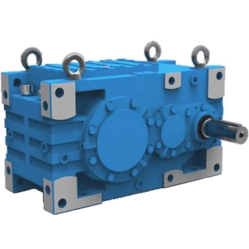
How do gear reducers contribute to energy efficiency in machinery and equipment?
Gear reducers play a significant role in enhancing energy efficiency in various machinery and equipment. Here’s how they contribute:
1. Speed Reduction: Gear reducers are commonly used to reduce the speed of the input shaft, allowing the motor to operate at a higher speed where it’s most efficient. This speed reduction helps match the motor’s optimal operating range, reducing energy consumption.
2. Torque Increase: Gear reducers can increase torque output while decreasing speed, enabling machinery to handle higher loads without the need for a larger, more energy-intensive motor.
3. Matching Load Requirements: By adjusting gear ratios, gear reducers ensure that the machinery’s output speed and torque match the load requirements. This prevents the motor from operating at unnecessary high speeds, saving energy.
4. Variable Speed Applications: In applications requiring variable speeds, gear reducers allow for efficient speed control without the need for continuous motor adjustments, improving energy usage.
5. Efficient Power Transmission: Gear reducers efficiently transmit power from the motor to the load, minimizing energy losses due to friction and inefficiencies.
6. Motor Downsizing: Gear reducers enable the use of smaller, more energy-efficient motors by converting their higher speed, lower torque output into the lower speed, higher torque needed for the application.
7. Decoupling Motor and Load Speeds: In cases where the motor and load speeds are inherently different, gear reducers ensure the motor operates at its most efficient speed while still delivering the required output to the load.
8. Overcoming Inertia: Gear reducers help overcome the inertia of heavy loads, making it easier for motors to start and stop, reducing energy consumption during frequent operation.
9. Precise Control: Gear reducers provide precise control over speed and torque, optimizing the energy consumption of machinery in processes that require accurate adjustments.
10. Regenerative Braking: In some applications, gear reducers can be used to capture and convert kinetic energy back into electrical energy during braking or deceleration, improving overall energy efficiency.
By efficiently managing speed, torque, and power transmission, gear reducers contribute to energy-efficient operation, reducing energy consumption, and minimizing the environmental impact of machinery and equipment.
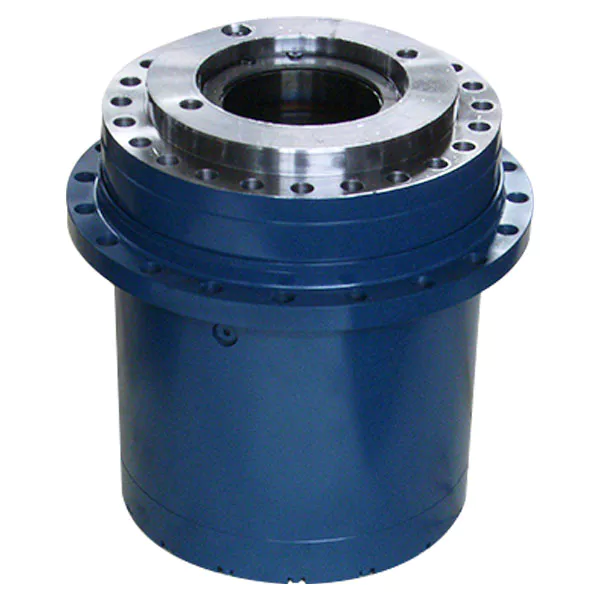
How do gear reducers ensure efficient power transmission and motion control?
Gear reducers play a vital role in ensuring efficient power transmission and precise motion control in various industrial applications. They achieve this through the following mechanisms:
- 1. Speed Reduction/Increase: Gear reducers allow you to adjust the speed between the input and output shafts. Speed reduction is essential when the output speed needs to be lower than the input speed, while speed increase is used when the opposite is required.
- 2. Torque Amplification: By altering the gear ratio, gear reducers can amplify torque from the input to the output shaft. This enables machinery to handle higher loads and provide the necessary force for various tasks.
- 3. Gear Train Efficiency: Well-designed gear trains within reducers minimize power losses during transmission. Helical and spur gears, for example, offer high efficiency by distributing load and reducing friction.
- 4. Precision Motion Control: Gear reducers provide precise control over rotational motion. This is crucial in applications where accurate positioning, synchronization, or timing is required, such as in robotics, CNC machines, and conveyor systems.
- 5. Backlash Reduction: Some gear reducers are designed to minimize backlash, which is the play between gear teeth. This reduction in play ensures smoother operation, improved accuracy, and better control.
- 6. Load Distribution: Gear reducers distribute the load evenly among multiple gear teeth, reducing wear and extending the lifespan of the components.
- 7. Shock Absorption: In applications where sudden starts, stops, or changes in direction occur, gear reducers help absorb and dampen shocks, protecting the machinery and ensuring reliable operation.
- 8. Compact Design: Gear reducers provide a compact solution for achieving specific speed and torque requirements, allowing for space-saving integration into machinery.
By combining these principles, gear reducers facilitate the efficient and controlled transfer of power, enabling machinery to perform tasks accurately, reliably, and with the required force, making them essential components in a wide range of industries.
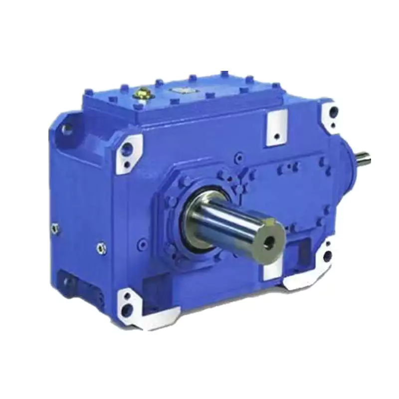
Are there variations in gear reducer designs for specific tasks and applications?
Yes, gear reducer designs vary widely to suit specific tasks and applications across various industries. Manufacturers offer a range of gear reducer types and configurations to accommodate different requirements, including:
- Helical Gear Reducers: These are versatile and provide smooth and efficient torque transmission. They are commonly used in applications requiring high precision and moderate speed reduction, such as conveyors, mixers, and agitators.
- Bevel Gear Reducers: These are ideal for transmitting power between intersecting shafts. They are often used in heavy machinery, printing presses, and automotive applications.
- Worm Gear Reducers: These provide compact solutions and are suitable for applications with higher speed reduction requirements, such as conveyor systems, winches, and elevators.
- Planetary Gear Reducers: These offer high torque density and are used in applications demanding precise control, such as robotics, aerospace, and heavy-duty machinery.
- Parallel Shaft Gear Reducers: Commonly used in industrial machinery, these reducers are designed for high torque and reliability.
- Right-Angle Gear Reducers: These are used when space limitations require a change in shaft direction, commonly found in packaging equipment and conveyors.
Each type of gear reducer has unique features and benefits that make it suitable for specific tasks. Manufacturers often provide customization options to tailor gear reducers to the precise requirements of an application, including gear ratios, mounting options, and input/output configurations.
Therefore, the variation in gear reducer designs allows industries to select the most appropriate type based on factors such as torque, speed, space constraints, precision, and environmental conditions.


editor by CX 2024-05-07
China Professional S Serial Helical Worm Right Angle Worm Reduction Gearbox Motor Worm Geared Speed Reducer Electric Motor with high quality
Product Description
| Input power | 250KW |
| Output torque | 10-62800N.m |
| Output speed | 7-415rpm |
| Mounting type | Foot mounted, foot mounted with CHINAMFG shaft, output flange mounted, hollow shaft mounted, B5 flange mounted with hollow shaft, foot mounted with hollow shaft, B14 flange mounted with hollow shaft, foot mounted with splined hole, foot mounted with shrink disk, hollow shaft mounted with anti-torque arm. |
| Input Method | Flange input(AM), shaft input(AD), inline AC motor input, or AQA servo motor |
| Brake Release | HF-manual release(lock in the brake release position), HR-manual release(autom-atic braking position) |
| Thermistor | TF(Thermistor protection PTC thermisto) TH(Thermistor protection Bimetal swotch) |
| Mounting Position | M1, M2, M3, M4, M5, M6 |
| Type | K37-K157 |
| Output shaft dis. | 25mm, 30mm, 35mm, 40mm, 50mm, 60mm, 70mm, 90mm, 110mm, 120mm |
| Housing material | HT200 high-strength cast iron from R37,47,57,67,77,87 |
| Housing material | HT250 High strength cast iron from R97 107,137,147, 157,167,187 |
| Heat treatment technology | carbonitriding and hardening treatment |
| Single Stage Efficiency | up to 96% |
| Lubricant | VG220 |
| Protection Class | IP55, F class |
1. Q: Can you make as per customer drawing?
A: Yes, we offer customized service for customers.
2. Q: Are you a factory or trading company?
A. We are a manufacturer in HangZhou, China.
3. Q: What’s your MOQ?
A: One piece.
4. Q: What’s your production time?
A: 5-7 working days after receiving payment; 1-2 days if urgent.
5. Q: What’s your payment terms?
A: T/T, 30% payment in advance, 70% balance payment should be paid before shipping.
6. Q: What’s your package?
A: carton or wooden box packaging.
7.Hong long is the warranty?
A: 12 months.
| Application: | Motor, Motorcycle, Machinery, Agricultural Machinery |
|---|---|
| Hardness: | Hardened Tooth Surface |
| Installation: | Horizontal Type |
| Layout: | Expansion |
| Gear Shape: | Bevel Gear |
| Step: | Stepless |
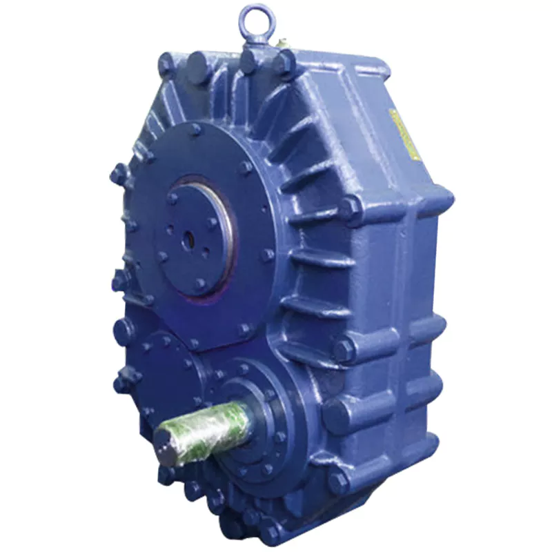
Are there any disadvantages or limitations to using gear reducer systems?
While gear reducer systems offer numerous advantages, they also come with certain disadvantages and limitations that should be considered during the selection and implementation process:
1. Size and Weight: Gear reducers can be bulky and heavy, especially for applications requiring high gear ratios. This can impact the overall size and weight of the machinery or equipment, which may be a concern in space-constrained environments.
2. Efficiency Loss: Despite their high efficiency, gear reducers can experience energy losses due to friction between gear teeth and other components. This can lead to a reduction in overall system efficiency, particularly in cases where multiple gear stages are used.
3. Cost: The design, manufacturing, and assembly of gear reducers can involve complex processes and precision machining, which can contribute to higher initial costs compared to other power transmission solutions.
4. Maintenance: Gear reducer systems require regular maintenance, including lubrication, inspection, and potential gear replacement over time. Maintenance activities can lead to downtime and associated costs in industrial settings.
5. Noise and Vibration: Gear reducers can generate noise and vibrations, especially at high speeds or when operating under heavy loads. Additional measures may be needed to mitigate noise and vibration issues.
6. Limited Gear Ratios: While gear reducers offer a wide range of gear ratios, there may be limitations in achieving extremely high or low ratios in certain designs.
7. Temperature Sensitivity: Extreme temperatures can affect the performance of gear reducer systems, particularly if inadequate lubrication or cooling is provided.
8. Shock Loads: While gear reducers are designed to handle shock loads to some extent, severe shock loads or abrupt changes in torque can still lead to potential damage or premature wear.
Despite these limitations, gear reducer systems remain widely used and versatile components in various industries, and their disadvantages can often be mitigated through proper design, selection, and maintenance practices.
What role do gear ratios play in optimizing the performance of gear reducers?
Gear ratios play a crucial role in optimizing the performance of gear reducers by determining the relationship between input and output speeds and torques. A gear ratio is the ratio of the number of teeth between two meshing gears, and it directly influences the mechanical advantage and efficiency of the gear reducer.
1. Speed and Torque Conversion: Gear ratios allow gear reducers to convert rotational speed and torque according to the needs of a specific application. By selecting appropriate gear ratios, gear reducers can either reduce speed while increasing torque (speed reduction) or increase speed while decreasing torque (speed increase).
2. Mechanical Advantage: Gear reducers leverage gear ratios to provide mechanical advantage. In speed reduction configurations, a higher gear ratio results in a greater mechanical advantage, allowing the output shaft to deliver higher torque at a lower speed. This is beneficial for applications requiring increased force or torque, such as heavy machinery or conveyor systems.
3. Efficiency: Optimal gear ratios contribute to higher efficiency in gear reducers. By distributing the load across multiple gear teeth, gear reducers with suitable gear ratios minimize stress and wear on individual gear teeth, leading to improved overall efficiency and prolonged lifespan.
4. Speed Matching: Gear ratios enable gear reducers to match the rotational speeds of input and output shafts. This is crucial in applications where precise speed synchronization is required, such as in conveyors, robotics, and manufacturing processes.
When selecting gear ratios for a gear reducer, it’s important to consider the specific requirements of the application, including desired speed, torque, efficiency, and mechanical advantage. Properly chosen gear ratios enhance the overall performance and reliability of gear reducers in a wide range of industrial and mechanical systems.
How do gear reducers handle variations in input and output speeds?
Gear reducers are designed to handle variations in input and output speeds through the use of different gear ratios and configurations. They achieve this by utilizing intermeshing gears of varying sizes to transmit torque and control rotational speed.
The basic principle involves connecting two or more gears with different numbers of teeth. When a larger gear (driving gear) engages with a smaller gear (driven gear), the rotational speed of the driven gear decreases while the torque increases. This reduction in speed and increase in torque enable gear reducers to efficiently adapt to variations in input and output speeds.
The gear ratio is a critical factor in determining how much the speed and torque change. It is calculated by dividing the number of teeth on the driven gear by the number of teeth on the driving gear. A higher gear ratio results in a greater reduction in speed and a proportionate increase in torque.
Planetary gear reducers, a common type, use a combination of gears including sun gears, planet gears, and ring gears to achieve different speed reductions and torque enhancements. This design provides versatility in handling variations in speed and torque requirements.
In summary, gear reducers handle variations in input and output speeds by using specific gear ratios and gear arrangements that enable them to efficiently transmit power and control motion characteristics according to the application’s needs.


editor by CX 2023-10-17
China OEM Aluminum Cast Iron Housing Transmission Drive Motor Shaft Smrv Series Reduction Helical Cycloidal Cyclo Planetary Worm Gearboxes gearbox design
Product Description
Worm gearbox speed reducer electric motor dc are on sale with high quality for you
SMRV 571-150 worm gear box with flange and electric motor
SMRV+NMRV Double Stage Arrangement Reduction Gear Box
RV Series Worm Gearbox
worm speed reducer
nmrv worm gear motor
You can choose the 1 type that you need form these product introction.
If you have any question,please contact me.
HangZhou CHINAMFG Machinery Co.,ltd is a company specialized in research, manufacture and service of speed gearbox. Ever since establishment, we have been persisting in technical innovation, advancing the techonology to our products while maintaining our strict quality controls. It is the reason that our products branding ”Xihu (West Lake) Dis.n” have enjoyed such successful global sales.
At present, our company mainly supplies 5 series products as RV worm gearbox, UDL series speed variator,PC series helical gear unit,G3 helical geared motor and SRC helical gearbox. The products are widely applied in the mechanical equipment field such as food and beverage,cement,package,chemical and dyeing, rubber and plastic, CNC machine tool,etc.
Our products have been processed ISO 9001 Quality System Certification and exported to Italy,Spain,Britain,Poland,Turkey.The USA and other European countries,earn the good reputation with our outstanding quality and service.
Customers first,customers satisfaction, excellent after sale service and incessant innovation are our tenet and motto. We will go all out to provide all the customers with high quality and service.
|
Shipping Cost:
Estimated freight per unit. |
To be negotiated |
|---|
| Application: | Motor, Electric Cars, Motorcycle, Machinery, Marine, Toy, Agricultural Machinery, Car |
|---|---|
| Hardness: | Hardened Tooth Surface |
| Installation: | Vertical Type |
| Customization: |
Available
| Customized Request |
|---|
Calculation of Reduction Ratio in a Cycloidal Gearbox
The reduction ratio in a cycloidal gearbox can be calculated using the following formula:
Reduction Ratio = (Number of Input Pins + Number of Output Pins) / Number of Output Pins
In a cycloidal gearbox, the input pins engage with the lobes of the cam disc, while the output pins are engaged with the cycloidal pins of the output rotor. The reduction ratio determines the relationship between the number of input and output pins engaged at any given time.
For example, if a cycloidal gearbox has 7 input pins and 14 output pins engaged, the reduction ratio would be:
Reduction Ratio = (7 + 14) / 14 = 1.5
This means that for every 1 revolution of the input pins, the output rotor will complete 1.5 revolutions. The reduction ratio is a key parameter that influences the output speed and torque of the cycloidal gearbox.
Patents Associated with Cycloidal Gearbox Designs
Throughout the history of cycloidal gearbox development, several patents have been filed for various designs and applications. Some notable patents include:
- Harmonic Drive: Ralph B. Heath’s patent for the “Harmonic Drive” (US Patent 2,906,143), filed in 1957, is one of the most famous patents related to cycloidal gear systems. This patent introduced the concept of a high-precision reduction gear mechanism using flexible components.
- Cycloidal Drive Mechanism: A patent by James Watt for a “Cycloidal Drive Mechanism” (GB Patent 1812), dating back to the 18th century, is often cited as one of the early references to cycloidal motion and gears.
- Planetary Roller Transmission: US Patent 3,671,927 by C.F. Kafesjian and H. Blumenstock introduced a “Planetary Roller Transmission” in 1972, describing a cycloidal drive mechanism with planetary motion.
- Cycloidal Speed Reducer: A patent for a “Cycloidal Speed Reducer” (US Patent 5,588,583) was granted to Richard J. Pieprzak in 1996, focusing on an improved design of cycloidal gears for various applications.
These patents represent a small sample of the numerous innovations and designs related to cycloidal gear systems that have been patented over the years. Patents play a significant role in protecting and promoting innovation in the field of gearbox technology.
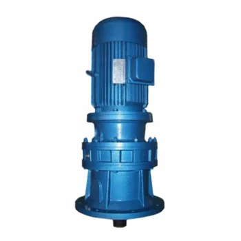
Common Applications of Cycloidal Gearboxes
Cycloidal gearboxes find their application in various industries and scenarios where their unique features are advantageous:
- Robotics: Cycloidal gearboxes are often used in robotic joints and manipulators due to their compact size, high torque capacity, and precision movement.
- Conveyor Systems: Their ability to handle heavy loads and provide accurate motion makes cycloidal gearboxes suitable for conveyor systems in industries such as manufacturing, food processing, and material handling.
- Aerospace: In aerospace applications, cycloidal gearboxes are used in satellite mechanisms, aerospace actuators, and precision motion control systems.
- Medical Devices: The compact design and precise motion capabilities of cycloidal gearboxes are beneficial in medical equipment such as surgical robots and diagnostic devices.
- Textile Industry: Cycloidal gearboxes are utilized in textile machines for their ability to provide accurate and synchronized movement in the weaving and knitting processes.
- Automotive: Some automotive applications, such as sunroof mechanisms and power seats, can benefit from the compact size and high torque capacity of cycloidal gearboxes.
- Printing Industry: The precision and reliability of cycloidal gearboxes are important in printing presses to ensure accurate paper feeding and positioning.
- Packaging Machinery: In packaging equipment, cycloidal gearboxes can provide the required torque and accuracy for tasks like sealing, labeling, and filling.
These are just a few examples of where cycloidal gearboxes are commonly used, demonstrating their versatility and adaptability across various industries.


editor by CX 2023-09-18
China Hot selling Reduction Gear Drive Zdy/Zly/Zsy/Zfy Seires Helical Electric Gearbox cycloidal gearbox reducer
Product Description
Product Description
Z Series Helical Gear Reducer
Z (ZDY, ZLY, ZSY, and ZFY) series hard tooth surface cylindrical gear reducer
D (DBY and DCY) series hard tooth surface cone gear reducer
ZDY/ZLY/ZSY/ ZFY series electric motor gear reducer 1:20 1:25 1:30 ratio reduction gearbox
Chinese speed reducer is widely used in mining machinery, chemical industry,steel metallurgy, light industry,environmental protection, paper making, printing, lifting transport, food industry and so on.
Main Series Product: R series helical gear reducer, K series spiral bevel gear reducer, NGW, P series planetary reducer, H B series gearbox, Z (ZDY, ZLY, ZSY, and ZFY) serial hard tooth surface cylindrical gear reducer, D (DBY and DCY) serial hard tooth surface cone gear reducer, cycloid reducer, etc. Meanwhile, map sample processing business can be undertaken.
Feature:
-
Applicable to the metallurgical,power generation,water treatment,construction,chemical,paper,
textiles,medicine,food and other industries.
-
The transmission efficiency of single-stage can reach up to 98%, two-stage can reach 96%, three-stage can reach 94%.
-
The gear processed by Carburizing & Grinding with high precision.
-
High precision gear, steady transmission, large load capacity
-
Long service life.
- One Two Three Stage Speed Reducer
Product Parameters
|
Applicable Industries |
Manufacturing Plant, Food & Beverage Factory, Farms, Retail, Construction works , Energy & Mining, Advertising Company |
|
Gearing Arrangement |
Helical |
|
Output Torque |
4~17000 |
|
Input Speed |
750~3500rpm |
|
Output Speed |
0.06~310 |
|
Place of Origin |
China |
|
Brand Name |
HUAKE |
|
Product name |
Gearbox |
|
Application |
Machine Tool |
|
Color |
Blue |
|
Ratio |
5-100 |
|
Mounting Position |
Horizontal (foot Mounted) |
|
Material |
Steel |
|
Certificate |
ISO9001 |
|
Warranty |
1 Year |
|
Heat treatment |
Quenching |
|
Keyword |
Gearbox |
Specification
| Driven machines | |||
| Waste water treatment | Thickeners,filter presses,flocculation apparata,aerators,raking equipment,combined longitudinal and rotary rakes,pre-thickeners,screw pumps,water turbines,centrifugal pumps | Dredgers | Bucket conveyors, dumping devices, carterpillar travelling gears, bucket wheel excavators as pick up, bucket wheel excavator for primitive material, cutter head, traversing gears |
| Chemical industry | Plate bending machines, extruders, dough mills, rubbers calenders, cooling drums, mixers for uniform media, agitators for media with uniform density, toasters, centrifuges | Metal working mills | plate tilters, ingot pushers, winding machines, cooling bed transfer frames, roller straigheners, table continuous intermittent, roller tables reversing tube mills, shears continuous, casting drivers, reversing CZPT mills |
| Metal working mills | Reversing slabbing mills. reversing wire mills, reversing sheet mills, reversing plate mill, roll adjustment drives | Conveyors | Bucket conveyors, hauling winches, hoists, belt conveyors, good lifts, passenger lifts, apron conveyors, escalators, rail travlling gears |
| Frequency converters | Reciprocating compressors | ||
| Cranes | Slewing gears, luffing gears, travelling gears, hoisting gear, derricking jib cranes | Cooling towers | Cooling tower fans, blowers axial and radial |
| Cane sugar production | Cane knives, cane mills | Beet sugar production | Beet cossettes macerators, extraction plants, mechanical refrigerators, juice boilers, sugar beet washing machines, sugar beet cutter |
| Paper machines | Pulper drives | Cableways | Material ropeways, continuous ropeway |
| Cement industry | Concrete mixer, breaker, rotary kilns, tube mills, separators, roll crushers | ||
Detailed Photos
Company Profile
| Application: | Motor, Electric Cars, Motorcycle, Machinery, Marine, Toy, Agricultural Machinery, Car, Power Transmission |
|---|---|
| Function: | Distribution Power, Clutch, Change Drive Torque, Change Drive Direction, Speed Changing, Speed Reduction, Speed Increase |
| Layout: | Cycloidal |
| Type: | Planetary Gear Box |
| Certificate: | CCC CE |
| Logo: | Support Custom |
| Samples: |
US$ 100/Piece
1 Piece(Min.Order) | |
|---|
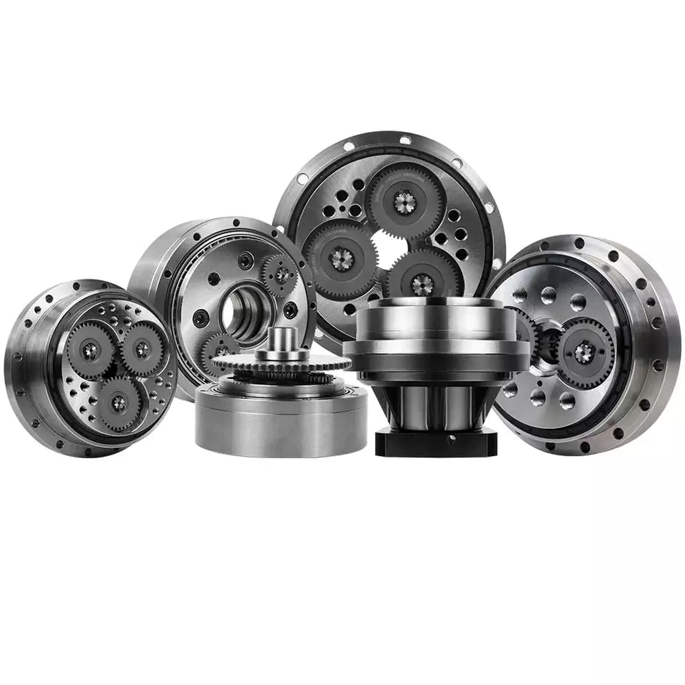
How to Calculate Transmission Ratio for a Cycloidal Gearbox
Using a cycloidal gearbox can be very useful in a wide variety of situations. However, it’s important to understand how to use it properly before implementing it. This article discusses the benefits of using a cycloidal gearbox, how to calculate the transmission ratio, and how to determine the effects of dynamic and inertial forces on the gearbox.
Dynamic and inertial effects
Various studies have been done to study the dynamic and inertial effects of cycloidal gearboxes. These studies have been performed using numerical, analytical and experimental methods. Depending on the nature of the load and its distribution along the gear, a variety of models have been developed. These models use finite element method to determine accurate contact stresses. Some of these models have been developed to address the nonlinear elasticity of contacts.
Inertial imbalance in a cycloidal gearbox causes vibration and can affect the efficiency of the device. This can increase mechanical losses and increase wear and tear. The efficiency of the device also depends on the torque applied to the cycloidal disk. The effectiveness of the device increases as the load increases. Similarly, the nonlinear contact dynamics are also associated with an increase in efficiency.
A new model of a cycloidal reducer has been developed to predict the effects of several operational conditions. The model is based on rigid body dynamics and uses a non-linear stiffness coefficient. The model has been validated through numerical and analytical methods. The model offers drastic reduction in computational costs. The model allows for a quick analysis of several operational conditions.
The main contribution of the paper is the investigation of the load distribution on the cycloidal disc. The study of this aspect is important because it allows for an analysis of the rotating parts and stresses. It also provides an indication of which gear profiles are best suited for optimizing torque transmission. The study has been conducted with a variety of cycloidal gearboxes and is useful in determining the performance of different types of cycloidal gearboxes.
To study the load distribution on the cycloidal disc, the authors investigated the relationship between contact force, cycloidal gearboxes and different gear profiles. They found that the non-linear contact dynamics have a large impact on the efficiency of a cycloidal gearbox. The cycloidal gearbox is an ideal solution for applications that involve highly dynamic servos. It can also be used in machine tool applications and food processing industries.
The study found that there are three common design principles of cycloidal reducers. These are the contact force distribution, the speed reduction and the trochoidal profile of the cycloidal disc. The trochoidal profile has to be defined carefully to ensure correct mating of the rotating parts. The trochoidal profile provides an indication of which gear profiles are best for optimizing torque transmission. The contact force distribution can be improved by refining the mesh along the disc’s width.
As the input speed increases, the efficiency of the reducer increases. This is because contact forces are constantly changing in magnitude and orientation. A cycloidal reducer with a one tooth difference can reduce input speed by up to 87:1 in a single stage. It also has the ability to handle high-cycle moves without backlash.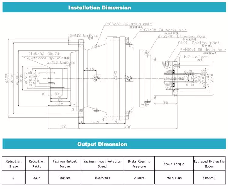
Transmission ratio calculation
Getting the correct transmission ratio calculation for a cycloidal gearbox requires a good understanding of what a gearbox is, as well as the product that it is being used for. The correct ratio is calculated by dividing the output speed of the output gear by the input speed of the input gear. This is usually accomplished by using a stopwatch. In some cases, a catalog or product specification may be required. The correct ratio is determined by a combination of factors, such as the amount of torque applied to the mechanism, as well as the size of the gears involved.
A cycloidal gear is a type of gear tooth profile that can be represented using a spline. It is also possible to model a gear with a cycloidal profile by using a spline to connect points against the beginning of a coordinate system. This is important in the design and functionality of a gear.
There are many different gears used in machines and devices. These include the herringbone gear, the helical gear and the spiral bevel gear. The best transmission ratios are typically obtained with a cycloidal gearbox. In addition to ensuring the accuracy of positioning, a cycloidal gearbox provides excellent backlash. Cycloid gears have a high degree of mechanical efficiency, low friction, and minimal moment of inertia.
A cycloidal gearbox is often referred to as a planetary gearbox, though it is technically a single-stage gearbox. In addition to having a ring gear, the gearbox has an eccentric bearing that drives the cycloidal disc in an eccentric rotation. This makes the cycloidal gearbox a good choice for high gear ratios in compact designs.
The cycloid disc is the key element of a cycloidal gearbox. The cycloid disc has n=9 lobes, and each lobe of the disc moves by a lobe for every revolution of the drive shaft. The cycloid disc is then geared to a stationary ring gear. The cycloidal disc’s lobes act like teeth on the stationary ring gear.
There are many different gears that are classified by the profile of the gear teeth. The most common gears are the involute and helical gears. Most motion control gears include spur designs. However, there are many other types of gears that are used in various applications. The cycloidal gear is one of the more complicated gears to design. The cycloid disc’s outline can be represented using markers or smooth lines, though a scatter chart will also do.
The cycloid disc’s lobes rotate on a reference pitch circle of pins. These pins rotate 40 deg during the eccentric rotation of the drive shaft. The pins rotate around the disc to achieve a steady rotation of the output shaft.
The cycloid disc’s other obvious, and possibly more important, feature is the’magic’ number of pins. This is the number of pins that protrude through the face of the disc. The disc has holes that are larger than the pins. This allows the pins to protrude through the disc and attach to the output shaft.
Application
Whether you’re building a robot drive or you’re simply looking for a gearbox to reduce the speed of your vehicle, a cycloidal gearbox is a great way to achieve a high reduction ratio. Cycloidal gearboxes are a low-friction, lightweight design that has an extremely stable transmission. They are suitable for industrial robots and can be used in many applications, including positioning robots.
Cycloidal gearboxes reduce speed by using eccentric motion. The eccentric motion enables the entire internal gear to rotate in wobbly cycloidal motion, which is then translated back into circular rotation. This eliminates the need for stacking gear stages. Cycloidal gearboxes also have less friction, higher strength, and greater durability than conventional gearboxes.
The cycloidal gearbox is also used in a number of applications, including marine propulsion systems, and robot drives. Cycloidal gearboxes reduce vibration by using offset gearing to cancel out vibrations.
Cycloidal gears have lower friction, higher strength, and better torsional stiffness than involute gears. They also have a reduced Hertzian contact stress, making them better than involute gears for use with shock loads. They also have a smaller size and weight than conventional gearboxes, and they have a higher reduction ratio than involute gears.
Cycloidal gears are typically used to reduce the speed of motors, but they also offer a number of other advantages. Cycloidal gearboxes have a smaller footprint than other gearboxes, allowing them to fit into confined spaces. They also have low backlash, allowing for precise movement. Cycloidal gears have a higher efficiency, resulting in lower power requirements and lower wear.
The cycloidal disc is one of the most important components of the gearbox. Cycloidal discs are normally designed with a short cycloid, which minimizes the eccentricity of the disc. They are also designed with a shortened flank, resulting in better strength and less stress concentration. Cycloidal discs are typically geared to a stationary ring gear. The cycloid is designed to roll around the stationary ring pins, which push against the circular holes in the disc. Cycloidal gearboxes typically employ two degrees of shift.
Cycloidal drives are ideal for heavy load applications. They also have high torsional stiffness, which makes them highly resistant to shock loads. Cycloidal drives also offer a high reduction ratio, which can be achieved without the need for a large input shaft. They are also compact and have a high service life.
The output shaft of a cycloidal gearbox always has two degrees of shifting, which ensures that the input and output shafts always rotate at a different speed. The output shaft would be a pin casing around the drive disks, which would also allow for easy maintenance.
Cycloidal gearboxes are also very compact and lightweight, so they are ideal for use in industrial robots. The cycloidal gearbox reducer is the most stable, low-vibration reducer in industrial robots, and it has a wide transmission ratio range.

editor by CX 2023-06-13
China Good quality Reduction Gear Drive Zdy/Zly/Zsy/Zfy Seires Helical Electric Gearbox small cycloidal gearbox
Product Description
SC Transmission
ZSY-ZDY-ZFY-ZLY-industrial-gearbox
Product Parameters
|
Applicable Industries |
Manufacturing Plant, Food & Beverage Factory, Farms, Retail, Construction works , Energy & Mining, Advertising Company |
|
Gearing Arrangement |
Helical |
|
Output Torque |
4~17000 |
|
Input Speed |
750~3500rpm |
|
Output Speed |
0.06~310 |
|
Place of Origin |
China |
|
Brand Name |
HUAKE |
|
Product name |
Gearbox |
|
Application |
Machine Tool |
|
Color |
Blue |
|
Ratio |
5-100 |
|
Mounting Position |
Horizontal (foot Mounted) |
|
Material |
Steel |
|
Certificate |
ISO9001 |
|
Warranty |
1 Year |
|
Heat treatment |
Quenching |
|
Keyword |
Gearbox |
Product Description
Characteristics
1.The gear is made of high strength low carbon alloy steel through carburization and quenching. The hardness of tooth surface may
reach to HRC58-62. All gear adapts NC tooth grinding process, high in accuracy and good in contactperformance;
2.High in transmission efficiency: single stage, more than 96.5%; double-stage, more than 93%; three-stage, more than 90%;
3.Smooth and stable in run, low noise;
4.Compact, light, long life, high bearing capacity;
5.Easy to disassemble, inspect and assemble.
Detailed Photos
Components:
1. Housing: Cast Iron or Steel Plate Welding
2. Gear Set: Hardened Helical Gear Pairs, Carburizing, Quenching, Grinding, Gear Hardness HRC54-62
3. Input Configurations:
Single or Double Keyed CZPT Shaft Input
4. Output Configurations:
Single or Double Keyed CZPT Shaft Output
5. Main Options: Backstop
Forced Lubrication Oil Pump
Cooling Fan, Cooling Coils
Features:
1. Optional welding steel plate gear box
2. High quality alloy steel helical gears, carburizing, quenching, grinding, large load capacity
3. Optimized design, interchangeable spare parts
4. High efficiency, high reliability, long service life, low noise
5. Output shaft rotation direction: clockwise, counterclockwise or bidirectional
6. A variety of shaft configurations: single or double input and output shaft in 1 side or 2 sides
7. Optional backstop and lengthening output shafts
Packaging & Shipping
Company Profile
| Application: | Motor, Electric Cars, Motorcycle, Machinery, Marine, Toy, Agricultural Machinery, Car, Power Transmission |
|---|---|
| Function: | Distribution Power, Clutch, Change Drive Torque, Change Drive Direction, Speed Changing, Speed Reduction, Speed Increase |
| Layout: | Cycloidal |
| Type: | Planetary Gear Box |
| Certificate: | CCC CE |
| Logo: | Support Custom |
| Samples: |
US$ 100/Piece
1 Piece(Min.Order) | |
|---|
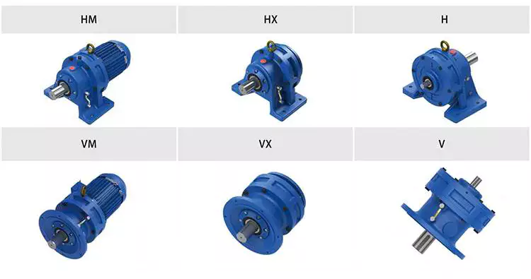
Condition Monitoring of Cyclone Gearboxes
Whether you’re considering using a cycloidal gearbox in your home, office, or garage, you’ll want to make sure it’s made of quality material. You also want to make sure it’s designed properly, so it won’t be damaged by vibrations.
Planetary gearboxes
Compared to cycloidal gearboxes, planetary gearboxes are lighter and more compact, but they lack the precision and durability of the former. They are better suited for applications with high torque or speed requirements. For this reason, they are usually used in robotics applications. But, cycloidal gearboxes are still better for some applications, including those involving shock loads.
There are many factors that affect the performance of gearboxes during production. One of these is the number of teeth. In the case of planetary gearboxes, the number of teeth increases with the number of planets. The number of teeth is reduced in cycloidal gearboxes, which results in higher transmission ratios. These gearboxes also have lower breakaway torques, which means that they can be controlled more easily by the user.
A cycloid gearbox is comprised of three main parts: the ring gear, the sun gear, and the input shaft. The ring gear is fixed in the gearbox, while the sun gear transmits the rotation to the planet gears. The input shaft transfers motion to the sun gear, which in turn transmits it to the output shaft. The output shaft has a larger torque than the input shaft.
Cycloid gears have better torsional stiffness, lower wear, and lower Hertzian contact stress. However, they are also larger in size and require highly accurate manufacturing. Cycloid gears can be more difficult to manufacture than involute gears, which require large amounts of precision.
Cycloid gears can offer transmission ratios up to 300:1, and they can do this in a small package. They also have lower wear and friction, which makes them ideal for applications that require a high transmission ratio.
Cycloid gearboxes are usually equipped with a backlash of about one angular minute. This backlash provides the precision and control necessary for accurate movement. They also provide low wear and shock load capacity.
Planetary gearboxes are available in single and two-stage designs, which increase in length as stages are added. In addition to the two stages, they can be equipped with an optional output bearing, which takes up mounting space. In some applications, a third stage is also available.
Involute gears
Generally, involute gears are more complex to manufacture than cycloidal gears. For example, an involute gear tooth profile has a single curve while a cycloidal gear tooth profile has two curves. In addition, the involute curve is not within the base circle.
The involute curve is a very important component of a gear tooth and it can significantly influence the quality of contact meshing between teeth. Various works have been done on the subject, mainly focusing on the operating principles. In addition, the most important characteristic of the double-enveloping cycloid drive is its double contact lines between the meshing tooth pairs.
Cycloid gears are more powerful, less noisy, and last longer than involute gears. They also require less manufacturing operations during production. However, cycloid gears are more expensive than involute gears. Involute gears are more commonly used in linear motions while cycloid gears are used for rotary motions.
Although cycloid gears are more technically advanced, involute gears have the superior quality and are more aesthetically pleasing. Cycloid gears are used in various industrial applications such as pumps and compressors. They are also widely used in the watch industry. Nevertheless, involute gears have not yet replaced cycloid gears in the watch industry.
The cycloid disc has a number of pins around its outer edge, while an involute gear has only a single curve for the teeth. In addition, cycloid gears have a more robust and reliable design. Involute gears, on the other hand, have a cheaper rack cutter and less expensive involute teeth.
The cycloid disc’s transmission accuracy is about 98.5%, while the ring gear’s transmission accuracy is about 96%. The cycloid disc’s rotational velocity has a magnitude of 3 rad/s. A small change in the center distance does not affect the transmission accuracy. However, rotational velocity fluctuation can affect the transmission accuracy.
Cycloid gears also have the cycloid gear disc’s rotational velocity. The disc has N lobes. However, the cycloid gear disc’s transmission accuracy is still not perfect. This is because of the large rotational angles between the lobes. This also makes it difficult to manufacture.
Vibrations
Using modern techniques for vibration diagnostics and data-driven methods, this article presents a new approach to condition monitoring of cycloidal gearboxes. This approach focuses on detecting the root cause of gearbox failure. The article aims to provide a unified approach to gear designers.
A cycloidal gearbox is a high-precision gearbox that is used in heavy-duty machines. It has a large reduction ratio, which makes it necessary to have a very large input speed. Cycloid gears have high accuracy, but they are susceptible to vibration issues. In this article, the authors describe how a cycloidal gearbox works and how vibrations are measured. They also show how this gearbox can be used to detect faults.
The gearbox is used in positioners, multi-axis robots, and heavy-duty machines. The main characteristics of this gearbox are the high accuracy, the overload capacity, and the large reduction ratio.
There is little documentation on vibrations and condition monitoring of cycloidal gearboxes. The authors describe their approach to the problem, using a cycloidal gearbox and a testing bench. Their approach involves measuring the frequency of the gearbox with different input speeds.
The results show a good separation between the healthy and damaged states. Fault frequencies show up in the lower orders of frequencies. Faults can be detected using binning, which eliminates the need for a tachometer. In addition, binning is combined with Principal Component Analysis to determine the state of the gearbox.
This method is compared to traditional techniques. In addition, the results show how binning can be used to calculate the defect frequencies of the bearings. It is also used to determine the frequencies of the components.
The signals from the test bench are acquired using four sensors. These sensors are medium sensitivity 100 mV/g accelerometers. The signals are then processed using different signal processing techniques. The results show that the vibration signals are correlated with the internal motion of the gearbox. This information is used to identify the internal frequency of the transmission.
The frequency analysis of vibration signals is performed in cyclostationary and noncyclostationary conditions. The signals are then analyzed to determine the magnitude of the gear meshing frequency.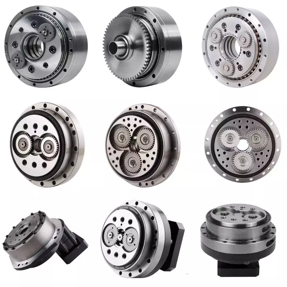
Design
Using precision gearboxes, servomotors can now control heavy loads at high speed. Unlike cam indexing devices, cycloidal gears provide extremely accurate positioning and high torque. They also provide excellent torsional stiffness and shock load capacity.
Cycloid gears are specially designed to minimize vibration at high RPM. Unlike involute gears, they are not stacked, which reduces friction and forces experienced by each tooth. In addition, cycloidal gears have lower Hertzian contact stress.
Cycloid gears are often used in multi-axis robots for positioners. They can provide transmission ratios as high as 300:1 in a compact package. They are also used in first joints in heavy machines. However, they require extremely accurate manufacturing. They are also more difficult to produce than involute gears.
A cycloidal gearbox is a type of planetary gearbox. Cycloid gears are specially designed for high gear ratios. They also have the ability to provide a large reduction ratio in a single stage. They are increasingly used in first joints in heavy machines. They are also becoming more common in robotics.
In order to achieve a large reduction ratio, the input speed of the gear must be very high. Generally, the input speed is between 500 rpm and 4500 rpm. However, in some cases, the input speed may be lower.
A cycloid is formed by rolling a rolling circle on a base circle. The ratio between the rolling circle diameter and the base circle diameter determines the shape of the cycloid. A hypocycloid is formed by rolling primarily on the inside of the base circle, while an epicycloid is formed by rolling primarily on the outside of the base circle.
Cycloid gears have a very small backlash, which minimizes the forces experienced by each tooth. These gears also have a good torsional stiffness, low friction, and shock load capacity. They also provide the best positioning accuracy.
The cycloidal gearbox was designed and built at Radom University. The design was based on three different cycloidal gears. The first pair had the external profile at the nominal dimension, while the second pair had the profile minus tolerance. The load plate had threaded screw holes arranged 15 mm away from the center.

editor by CX 2023-06-01
China SWL screw jack for lift system power transmission 180 ratio reduction gearbox shaft mount reducer bevel helical gear unit with Best Sales
Guarantee: 3 years
Applicable Industries: Creating Substance Retailers, Equipment Fix Retailers, Foods & Beverage Factory, Farms, Cafe, Property Use, Design works, 1 way clutch deep groove ball bearing CSK6304 CSK6305 CSK6306 P PP CSK6304P CSK6305P CSK6306P CSK6304PP CSK6305PP CSK6306PP Strength & Mining
Bodyweight (KG): 30 KG
Personalized help: OEM, ODM, OBM
Gearing Arrangement: Worm
Enter Pace: three hundred
Output Speed: 300
Certification: ISO9001-2008, CE
Lifting Potential: As request
Equipment material: Lower carbon higher alloy metal
Heat therapy: Carburising, quenching, gear grinding
Packaging Details: Standard exporting package deal
Port: HangZhou Port, ZheJiang Port
SWL sequence Screw jack for carry program tables has the features of compacted construction, OEM 55GP micro steel equipment motor twelve v 12v 24v large torque 25nm 50nm 40nm 100kg 60 minimal 300 rpm 120w brush dc planetary gearmotor light and moveable, versatile, trustworthy, lengthy provider life, straightforward to installation, and self-locking whilst cease.
Certifications
Trade Exhibits
Packaging & ShippingPacking Information : Normal carton/Pallet/Regular picket scenario
Shipping and delivery Information : 15-30 working times upon payment
Company Details
other series product
| Precision Planetary gearbox | Robotic RV gearbox speed reducer |
| Personalized manufactured Non-regular Gearbox | UDL Collection Variator |
| PYZ Sequence Helical Tooth Shaft Mounted Reducer | 8000 Collection Cycloidal Reducer |
| SLT Series Spiral Bevel Gearbox | SLSWL Collection Worm Screw Jack |
| SLP Series Planetary Reducer | SLH/SLB Series Substantial Power Reducer |
| NMRV Sequence Worm Reducer | BKM Sequence Helical-hypoid Reducer |
| SLRC Series Helical Reducer | SLSMR Collection Shaft Mounted Reducer |
| SLXG Sequence Shaft Mounted Reducer | X/B Sequence Cycloidal Reducer |
| SLR/SLF/SLK/SLS Sequence Helical Reducer |
Speak to
What Is a Gearbox?
There are several factors to consider when choosing a gearbox. Backlash, for example, is a consideration, as it is the angle at which the output shaft can rotate without the input shaft moving. While this isn’t necessary in applications without load reversals, it is important for precision applications involving load reversals. Examples of these applications include automation and robotics. If backlash is a concern, you may want to look at other factors, such as the number of teeth in each gear.
Function of a gearbox
A gearbox is a mechanical unit that consists of a chain or set of gears. The gears are mounted on a shaft and are supported by rolling element bearings. These devices alter the speed or torque of the machine they are used in. Gearboxes can be used for a wide variety of applications. Here are some examples of how gearboxes function. Read on to discover more about the gears that make up a gearbox.
Regardless of the type of transmission, most gearboxes are equipped with a secondary gear and a primary one. While the gear ratios are the same for both the primary and secondary transmission, the gearboxes may differ in size and efficiency. High-performance racing cars typically employ a gearbox with two green and one blue gear. Gearboxes are often mounted in the front or rear of the engine.
The primary function of a gearbox is to transfer torque from one shaft to another. The ratio of the driving gear’s teeth to the receiving member determines how much torque is transmitted. A large gear ratio will cause the main shaft to revolve at a slower speed and have a high torque compared to its counter shaft. Conversely, a low gear ratio will allow the vehicle to turn at a lower speed and produce a lower torque.
A conventional gearbox has input and output gears. The countershaft is connected to a universal shaft. The input and output gears are arranged to match the speed and torque of each other. The gear ratio determines how fast a car can go and how much torque it can generate. Most conventional transmissions use four gear ratios, with one reverse gear. Some have two shafts and three inputs. However, if the gear ratios are high, the engine will experience a loss of torque.
In the study of gearbox performance, a large amount of data has been collected. A highly ambitious segmentation process has yielded nearly 20,000 feature vectors. These results are the most detailed and comprehensive of all the available data. This research has a dual curse – the first is the large volume of data collected for the purpose of characterization, while the second is the high dimensionality. The latter is a complication that arises when the experimental gearbox is not designed to perform well.
Bzvacklash
The main function of a gearhead is to multiply a moment of force and create a mechanical advantage. However, backlash can cause a variety of issues for the system, including impaired positioning accuracy and lowered overall performance. A zero backlash gearbox can eliminate motion losses caused by backlash and improve overall system performance. Here are some common problems associated with backlash in gearheads and how to fix them. After you understand how to fix gearbox backlash, you’ll be able to design a machine that meets your requirements.
To reduce gearbox backlash, many designers try to decrease the center distance of the gears. This eliminates space for lubrication and promotes excessive tooth mesh, which leads to premature mesh failure. To minimize gearbox backlash, a gear manufacturer may separate the two parts of the gear and adjust the mesh center distance between them. To do this, rotate one gear with respect to the fixed gear, while adjusting the other gear’s effective tooth thickness.
Several manufacturing processes may introduce errors, and reducing tooth thickness will minimize this error. Gears with bevel teeth are a prime example of this. This type of gear features a small number of teeth in comparison to its mating gear. In addition to reducing tooth thickness, bevel gears also reduce backlash. While bevel gears have fewer teeth than their mating gear, all of their backlash allowance is applied to the larger gear.
A gear’s backlash can affect the efficiency of a gearbox. In an ideal gear, the backlash is zero. But if there is too much, backlash can cause damage to the gears and cause it to malfunction. Therefore, the goal of gearbox backlash is to minimize this problem. However, this may require the use of a micrometer. To determine how much gearbox backlash you need, you can use a dial gauge or feeler gauge.
If you’ve been looking for a way to reduce backlash, a gearbox’s backlash may be the answer. However, backlash is not a revolt against the manufacturer. It is an error in motion that occurs naturally in gear systems that change direction. If it is left unaccounted for, it can lead to major gear degradation and even compromise the entire system. In this article, we’ll explain how backlash affects gears and how it affects the performance of a gearbox.
Design
The design of gearboxes consists of a variety of factors, including the type of material used, power requirements, speed and reduction ratio, and the application for which the unit is intended. The process of designing a gearbox usually begins with a description of the machine or gearbox and its intended use. Other key parameters to consider during gearbox design include the size and weight of the gear, its overall gear ratio and number of reductions, as well as the lubrication methods used.
During the design process, the customer and supplier will participate in various design reviews. These include concept or initial design review, manufacturing design validation, critical design review, and final design review. The customer may also initiate the process by initiating a DFMEA. After receiving the initial design approval, the design will go through several iterations before the finalized design is frozen. In some cases, the customer will require a DFMEA of the gearbox.
The speed increaser gearboxes also require special design considerations. These gearboxes typically operate at high speeds, causing problems with gear dynamics. Furthermore, the high speeds of the unit increase frictional and drag forces. A proper design of this component should minimize the effect of these forces. To solve these problems, a gearbox should incorporate a brake system. In some cases, an external force may also increase frictional forces.
Various types of gear arrangements are used in gearboxes. The design of the teeth of the gears plays a significant role in defining the type of gear arrangement in the gearbox. Spur gear is an example of a gear arrangement, which has teeth that run parallel to the axis of rotation. These gears offer high gear ratios and are often used in multiple stages. So, it is possible to create a gearbox that meets the needs of your application.
The design of gearboxes is the most complex process in the engineering process. These complex devices are made of multiple types of gears and are mounted on shafts. They are supported by rolling element bearings and are used for a variety of applications. In general, a gearbox is used to reduce speed and torque and change direction. Gearboxes are commonly used in motor vehicles, but can also be found in pedal bicycles and fixed machines.
Manufacturers
There are several major segments in the gearbox market, including industrial, mining, and automotive. Gearbox manufacturers are required to understand the application and user industries to design a gearbox that meets their specific requirements. Basic knowledge of metallurgy is necessary. Multinational companies also provide gearbox solutions for the power generation industry, shipping industry, and automotive industries. To make their products more competitive, they need to focus on product innovation, geographical expansion, and customer retention.
The CZPT Group started as a small company in 1976. Since then, it has become a global reference in mechanical transmissions. Its production range includes gears, reduction gearboxes, and geared motors. The company was the first in Italy to achieve ISO certification, and it continues to grow into one of the world’s leading manufacturers of production gearboxes. As the industry evolves, CZPT focuses on research and development to create better products.
The agriculture industry uses gearboxes to implement a variety of processes. They are used in tractors, pumps, and agricultural machinery. The automotive industry uses gears in automobiles, but they are also found in mining and tea processing machinery. Industrial gearboxes also play an important role in feed and speed drives. The gearbox industry has a diverse portfolio of manufacturers and suppliers. Here are some examples of gearboxes:
Gearboxes are complex pieces of equipment. They must be used properly to optimize efficiency and extend their lifespan. Manufacturers employ advanced technology and strict quality control processes to ensure their products meet the highest standards. In addition to manufacturing precision and reliability, gearbox manufacturers ensure that their products are safe for use in the production of industrial machinery. They are also used in office machines and medical equipment. However, the automotive gearbox market is becoming increasingly competitive.


editor by czh 2023-02-17
China KOOD Helical reduction gearbox motor speed reducer 220V 380V 50HZ 60HZ AC electric moderator gear motor speed reducer cvt gearbox
Warranty: 1 year
Applicable Industries: Hotels, Building Material Shops, Manufacturing Plant, Machinery Repair Shops, Food & Beverage Factory, Farms, Home Use, Retail, Printing Shops, Construction works , Energy & Mining, Food & Beverage Shops, Other, Advertising Company
Weight (KG): 168 KG
Customized support: OEM, ODM, OBM
Gearing Arrangement: Helical, Helical
Output Torque: 3.5-56845N.m, 3.5-56845N.m
Input Speed: 0-3000rpm/min, 0-3000rpm/min
Output Speed: 0.1-356rpm/min, 0.1-356rpm/min
Product name: F Series Parallel Shaft Helical Gear Reducer
Input power: 0.12-250kw
Mounting Position: Foot Mounted. Flange Mounted
Ratio: 3.77~281.71
Reduction ratio: 68
Hardness of Tooth Surface: Tooth surface hardness
Packaging Details: International standard packaging or as your requirements
Port: ShenZhen, HangZhou, ZheJiang and other ports
F SERIES PARALLEL SHAFT HELICAL GEAR REDUCERF series parallel shaft helical gear reducer has the characteristics of small volume, light weight, large transfer torque, lowenergy consumption, high efficiency, low temperature rise, strong load force and various structure forms. Suitable for different installation conditions.It can be combined with R series, K series, S series, etc. to obtain lower speed and greater torque. HIGH QUALITY SHELL MATERIALThe box body is made of HT200 material, which is cleaned by professional screeni feeds.htmng and washing equipment to ensure that the innerThe cavity of the box body is cleaner without iron filings. PROFESSIONAL AIR TIGHTNESS TESTBefore spraying each reducer, an air tightnes feeds.htms test is needed to minimize the occurrence of oil leakage and air leakage. Ensurethe long life and good operation of the reducer. Specification
| item | value |
| Warranty | 1 year |
| Applicable Industries | Hotels, Building Material Shops, Manufacturing Plant, Machinery Repair Shops, Food & Beverage Factory, Farms, Home Use, Retail, Printing Shops, Construction works , Energy & Mining, Food & Beverage Shops, Other, Advertising Company |
| Weight (KG) | 150KG |
| Customized support | OEM, ODM, OBM |
| Gearing Arrangement | Helical |
| Output Torque | 3.5-56845N.m |
| Input Speed | 0-3000rpm/min |
| Output Speed | 0.1-356rpm/min |
| Place of Origin | China |
| ZheJiang | |
| Brand Name | KOOD |
| Product name | F Series Parallel Shaft Helical Gear Reducer |
| Output Torque | 3.5-56845N.m |
| Output Speed | 0.1-356rpm/min |
| Input Speed | 0-3000rpm/min |
| Input power | 0.12-250kw |
| Mounting Position | Foot Mounted. Flange Mounted |
| Ratio | 3.77~281.71 |
| Gearing Arrangement | Helical |
| Reduction ratio | 68 |
| Hardness of Tooth Surface | Tooth surface hardness |
The Parts of a Gearbox
There are many parts of a Gearbox, and this article will help you understand its functions and components. Learn about its maintenance and proper care, and you’ll be on your way to repairing your car. The complexity of a Gearbox also makes it easy to make mistakes. Learn about its functions and components so that you’ll be able to make the best choices possible. Read on to learn more. Then, get your car ready for winter!
Components
Gearboxes are fully integrated mechanical components that consist of a series of gears. They also contain shafts, bearings, and a flange to mount a motor. The terms gearhead and gearbox are not often used interchangeably in the motion industry, but they are often synonymous. Gearheads are open gearing assemblies that are installed in a machine frame. Some newer designs, such as battery-powered mobile units, require tighter integration.
The power losses in a gearbox can be divided into no-load and load-dependent losses. The no-load losses originate in the gear pair and the bearings and are proportional to the ratio of shaft speed and torque. The latter is a function of the coefficient of friction and speed. The no-load losses are the most serious, since they represent the largest proportion of the total loss. This is because they increase with speed.
Temperature measurement is another important preventive maintenance practice. The heat generated by the gearbox can damage components. High-temperature oil degrades quickly at high temperatures, which is why the sump oil temperature should be monitored periodically. The maximum temperature for R&O mineral oils is 93degC. However, if the sump oil temperature is more than 200degF, it can cause seal damage, gear and bearing wear, and premature failure of the gearbox.
Regardless of its size, the gearbox is a crucial part of a car’s drivetrain. Whether the car is a sports car, a luxury car, or a farm tractor, the gearbox is an essential component of the vehicle. There are two main types of gearbox: standard and precision. Each has its own advantages and disadvantages. The most important consideration when selecting a gearbox is the torque output.
The main shaft and the clutch shaft are the two major components of a gearbox. The main shaft runs at engine speed and the countershaft may be at a lower speed. In addition to the main shaft, the clutch shaft has a bearing. The gear ratio determines the amount of torque that can be transferred between the countershaft and the main shaft. The drive shaft also has another name: the propeller shaft.
The gears, shafts, and hub/shaft connection are designed according to endurance design standards. Depending on the application, each component must be able to withstand the normal stresses that the system will experience. Oftentimes, the minimum speed range is ten to twenty m/s. However, this range can differ between different transmissions. Generally, the gears and shafts in a gearbox should have an endurance limit that is less than that limit.
The bearings in a gearbox are considered wear parts. While they should be replaced when they wear down, they can be kept in service much longer than their intended L10 life. Using predictive maintenance, manufacturers can determine when to replace the bearing before it damages the gears and other components. For a gearbox to function properly, it must have all the components listed above. And the clutch, which enables the transmission of torque, is considered the most important component.
Functions
A gearbox is a fully integrated mechanical component that consists of mating gears. It is enclosed in a housing that houses the shafts, bearings, and flange for motor mounting. The purpose of a gearbox is to increase torque and change the speed of an engine by connecting the two rotating shafts together. A gearbox is generally made up of multiple gears that are linked together using couplings, belts, chains, or hollow shaft connections. When power and torque are held constant, speed and torque are inversely proportional. The speed of a gearbox is determined by the ratio of the gears that are engaged to transmit power.
The gear ratios in a gearbox are the number of steps a motor can take to convert torque into horsepower. The amount of torque required at the wheels depends on the operating conditions. A vehicle needs more torque than its peak torque when it is moving from a standstill. Therefore, the first gear ratio is used to increase torque and move the vehicle forward. To move up a gradient, more torque is required. To maintain momentum, the intermediate gear ratio is used.
As metal-to-metal contact is a common cause of gearbox failure, it is essential to monitor the condition of these components closely. The main focus of the proactive series of tests is abnormal wear and contamination, while the preventative tests focus on oil condition and additive depletion. The AN and ferrous density tests are exceptions to this rule, but they are used more for detecting abnormal additive depletion. In addition, lubrication is critical to the efficiency of gearboxes.
Maintenance
Daily maintenance is a critical aspect of the life cycle of a gearbox. During maintenance, you must inspect all gearbox connection parts. Any loose or damaged connection part should be tightened immediately. Oil can be tested using an infrared thermometer and particle counters, spectrometric analysis, or ferrography. You should check for excessive wear and tear, cracks, and oil leaks. If any of these components fail, you should replace them as soon as possible.
Proper analysis of failure patterns is a necessary part of any preventative maintenance program. This analysis will help identify the root cause of gearbox failures, as well as plan for future preventative maintenance. By properly planning preventative maintenance, you can avoid the expense and inconvenience of repairing or replacing a gearbox prematurely. You can even outsource gearbox maintenance to a company whose experts are knowledgeable in this field. The results of the analysis will help you create a more effective preventative maintenance program.
It is important to check the condition of the gearbox oil periodically. The oil should be changed according to its temperature and the hours of operation. The temperature is a significant determinant of the frequency of oil changes. Higher temperatures require more frequent changes, and the level of protection from moisture and water reduces by 75%. At elevated temperatures, the oil’s molecular structure breaks down more quickly, inhibiting the formation of a protective film.
Fortunately, the gear industry has developed innovative technologies and services that can help plant operators reduce their downtime and ensure optimal performance from their industrial gears. Here are 10 steps to ensure that your gearbox continues to serve its purpose. When you are preparing for maintenance, always keep in mind the following tips:
Regular vibration analysis is a vital part of gearbox maintenance. Increased vibration signals impending problems. Visually inspect the internal gears for signs of spiraling and pitting. You can use engineers’ blue to check the contact pattern of gear teeth. If there is a misalignment, bearings or housings are worn and need replacement. Also make sure the breathers remain clean. In dirty applications, this is more difficult to do.
Proper lubrication is another key factor in the life of gearboxes. Proper lubrication prevents failure. The oil must be free of foreign materials and have the proper amount of flow. Proper lubricant selection depends on the type of gear, reduction ratio, and input power. In addition to oil level, the lubricant must be regulated for the size and shape of gears. If not, the lubricant should be changed.
Lack of proper lubrication reduces the strength of other gears. Improper maintenance reduces the life of the transmission. Whether the transmission is overloaded or undersized, excessive vibration can damage the gear. If it is not properly lubricated, it can be damaged beyond repair. Then, the need for replacement gears may arise. However, it is not a time to waste a lot of money and time on repairs.


editor by czh
in Gaoxiong China, Taiwan Province of China sales price shop near me near me shop factory supplier Assembly Reduction Gear Reducer Motor Drive Wheel Right Angle Stainless Steel Self Locking Helical Application Small NEMA Winch Worm Gearbox Manufacturer manufacturer best Cost Custom Cheap wholesaler

Getting amassed cherished experience in cooperating with international consumers, Our merchandise are utilized in a lot of fields. Quality and credit score are the bases that make a company alive.
assembly reduction EPTT EPTT motor EPTT wheel rigEPTT angle stainless metal self locking helical software small nema winch worm EPTT company


in Benguela Angola sales price shop near me near me shop factory supplier Combinatorial Helical Bevel Reduction Gearbox manufacturer best Cost Custom Cheap wholesaler

assures the stability and regularity of the important function of components. Our products are produced by contemporary computerized equipment and equipment. Our solution selection also covers locking assemblies (clamping components/locking device), taper bushes, QD bushes, bolt-on hubs, torque limiters, shaft collars, motor bases and motor slides, chain detachers, chain guides, universal joint, rod finishes and yokes.
gt Item Introduction
K/Ka 180HP/CV 132kw Velocity Reduction EPTT
K helical velocity EPTT motor is created primarily based on modularization, which deliver numerous variation varieties of combinations, mounting varieties, and framework types. The detail classification of ratio can meet different of operating issue. Large EPTT efficiency, minimal energy intake, exceptional functionality. The hard tooth floor EPTT use the higher high quality alloy metal, the approach of carburizing and quenching, grinding ,which give it pursuing characters: Stable EPTT, reduced noise and temperature, high loading, EPTT functioning lifestyle.
gt EPTT EPTTs
| housing material: | EPTT2OO higher-strength cast iron or EPTT250 Higher strength cast iron |
| Gear material: | 20CrMnTi |
| EPTT hardness | HBS90-240 |
| Floor hardness of EPTT | EPTC58 deg-62 deg |
| Equipment main hardness | EPTC33 deg-40 deg |
| Input/Output shaft materials | 40Cr |
| Input/Output shaft hardness | HBS241 deg-286 deg |
| Shaft at oil seal placement hardness | EPTC48 deg -55 deg |
| Machining precision of EPTTs content | Correct grinding 6-five quality |
| Effectiveness | up to ninety eight% |
| Noise(Max) | sixty-68dB |
| Temp.rise: | 40 degC |
| Vibration | le20um |
| EPTT | IP54, F course ,B5 FLANGE |
| shade : | blue (if you require big quantity ,we can carried out as your needed color ) |
gt Partial Item Info
gt Our Electric powered EPTT Rewards
one. Realistic price tag with superb quality
two.Every single 1 exams very carefully
three.Very clear nameplate
four.Reputable bundle
five.Higher performance, sleek runingand minimal sound
6.Ideal resources make very best performance
gt Making Procedure
gt About Us
HangEPTT EXTENSION Speed EPTTITY CO.,LTD (HangEPTT Great COMMERCE amp EPTT CO.LTD) EPTTizes in the income of all varieties of EPTT , electric powered motors. On the revenue support and management has accumulated abundant expertise, has a amount of hugely experienced technological staff, management norms, top quality isstable. EPTT by the EPTT countrywide mXiHu (West Lake) Dis.Hu (West Lake) Dis.tory product certification, good quality is reliable, realistic framework,and make quotenvironmental safety quot and quotenergy conserving quot synchronization.
HangEPTT Great COMMERCE amp EPTT CO.,LTD(EPTT ) has alwaEPTTbeen in line with: quotbased on sincerity, excellent good quality for very first, the pursuit of excellence, pioneering and EPTTrprising team, effective, innovation quot . excellent aftersales support We will established up a business unEPTTthe bridge of friendship, hand in hand Develop EPTT!
FAQ
one, Q:what is your MOQ for ac EPTT motor ?
A: 1pc is okay for each kind electric powered EPTT box motor
two, Q: What about your warranty for your induction velocity EPTT motor ?
A: 1 calendar year ,but except gentleman-manufactured destroyed
3, Q: which payment way you can accept ?
A: TT, western union .
4, Q: how about your payment way ?
A: a hundred%payment EPTTd significantly less $5000 ,30% payment EPTTd payment , 70% payment ahead of sending above $5000.
5, Q: how about your EPTT of pace reduction motor ?
A: plywood case ,if dimensions is little ,we will pack with pallet for less one container
6, Q: What data need to be offered, if I acquire electric helical EPTTed motor from you ?
A: rated EPTT, ratio or output pace,sort ,voltage , mounting way , amount , if a lot more is much better.


in Santiago Dominican Republic sales price shop near me near me shop factory supplier Worm Reduction Gear Box Speed Reducer Jack Worm Agricultural Planetary Helical Bevel Worm Steering Gear Drive Motor High Speed Nmrv Gearbox Reducer Manufacture manufacturer best Cost Custom Cheap wholesaler

We also can style and make non-normal merchandise to fulfill customers’ unique specifications. Sophisticated thermo treatment method gear, such as community warmth treatment method oven, multi-use thermo treatment oven, and so on. If you require any information or samples, remember to get in touch with us and you will have our soon reply.
Worm Reduction Gear Box Speed EPTT Jack Worm Agricultural Planetary Helical EPTTl Worm Steering Gear Drive EPTT Higher Pace Nmrv EPTT EPTT Manufacture

