Nylon gear racks is used on sliding gate, There may be steel core inside it. we exported to Europe in big amount. There’s steel core inside the nylon gear rack.There are two items out there. There are actually 4 eye(four bracket is light form) and 6 eyes(six brackets is heavy form).Each piece of nylon gear rack with screw set Manufacturer supplier exporter of gear rack We exported gear rack in big quantity to Europe, America, Australia, Brazil, South Africa, Russia and so forth. There’s regular gear rack readily available as well as specific gear rack as per your drawing or samples. Our gear racks developed by CNC machines There exists quite a few sizes of steel gears rack for sliding door also. M4 8?¨¢30, M4 9?¨¢30, M4 10?¨¢30, M4 11?¨¢30, M4 12?¨¢30, M4 20?¨¢20, M4 22?¨¢22, M6 30?¨¢30 and so on For M4 8?¨¢30, M4 9?¨¢30, M4 10?¨¢30, M4 11?¨¢30, M4 12?¨¢30, 1M length have three bolt,nut, washer sets and each and every 4pcs or 6pcs packed into carton box after which place into steel pallet. For M4 8?¨¢30, M4 9?¨¢30, M4 10?¨¢30, M4 11?¨¢30, M4 12?¨¢30, 2M length have 4 bolt,nut, washer sets. We will also supply the sliding gate portion such as sliding door pulley, wheel, roller and so forth. Please kindly test and let me know your detail request When you want 2M or 3M, or any other length, we are able to create as per your requests Nearly all of our customer will send us drawing and we will produce as per your drawing or sample. We make Module M1-M8 racks, CP and DP British regular racks. The utmost length from the rack is 2 meters. Our goods happen to be broadly used in lots of fields this kind of as automatic doors, window openers, engraving machines, lifters, escalators, automated warehousing, food machinery, energy resources, machine tools, precision transmission, and so on.
We exported gear rack in major quantity to Europe, America, Australia, Brazil, South Africa, Russia and so on. There is conventional gear rack obtainable and in addition special gear rack as per your drawing or samples. Our gear racks created by CNC machines.
Our gear racks are used for window machine, engraving machine, lift machine, opener rack, CNC machine, automobile, industrial usage so on. 1) Our gear rack is developed as per DIN requirements by CNC machine 2) The pressure angle: 20??/14.5?? three) Module: M0.4-M36/DP1-DP25 four) The utmost length could be 3500mm five) The material is usually Q235, C45, SS304, SS316L, aluminum, copper, nylon and so on. Our gear racks are utilized for window machine, engraving machine, lift machine, opener rack, CNC machine, automobile, industrial utilization so on. Industrial Gear Rack Lorem ipsum dolor sit amet, consectetur adipiscing elit, sed do eiusmod tempor incididunt ut labore et dolore magna aliqua.
We will also supply Construction lift gear rack,American regular gears racks,steel gear rack,helical gear rack,versatile gear racks,power steering rack,steering gear rack ,stainless steel gear rack ,round rack gear ,nylon gear rack ,spur gear rack ,boston gear rack ,audia gear rack ,gears racks ,rack and pinion gear 1. Wealthy business experience considering the fact that 1988. 2. Broad organize merchandise line, which include plastics sheet/rod/parts/accessories: MC NYLON, OIL NYLON, POM, UHMW-PE, PU, PETP, Pc, PTFE, PVDF, PPS, PEEK, PAI, PI, PBI ect. 3. Manufacture, design and style and processing service as per your demand 1. Great Tensile power; two. Large effect and notching impact strength; 3. Substantial heat deflection temperature ; four. Large power and stiffness; five. Very good glide and limp dwelling characters; 6. Excellent chemical stability towards organic solvents and fuels; 7. Resistant to thermal aging (applicable temperature involving -50??C and 110??C; 8. Size alternation by humidity absorption need to be regarded as;
Shaft sleeve, bearing bush, lining, lining plate, gear; Worm gear, roller copper manual rail, piston ring, seal ring, slide block; Spheric bowl, impeller, blade, cam, nut, valve plate, Pipe, stuffing box, rack, belt pulley, pump rotor, and so on.rack pinion gear for elevator in stockoperator Steel and Nylon gear rack SPUR GEAR RACK AND PINION nylon gear rack iron gear rack We warmly welcome consumers the two in the home and abroad to speak to us to negotiate organization, exchange information and facts and cooperate with us.
We specializing while in the production of Agricultural Gearbox, PTO Shafts, Sprockets, Fluid Coupling, Worm Gear Reducers, Gears and racks, Roller Chains, Sheave and Pulleys, Planetary Gearboxes, Timing Pulleys, Shaft Collars and more. Taper Lock Pulley V Belt Pulley We offer high quality Taper Lock Pulley V Belt Pulley in aggressive selling price v pulley, v belt pulleys, taper lock pulley,v belt pulleys ,v pulley,v groove pulleys,v groove belt pulley,taper lock pulley,taper lock v belt pulleys,taper lock bushing pulley,taper lock pulleys/ taper bore pulley,significant v belts pulley,double v belts pulley,cast iron v belt pulleys belt pulley,variable pace v belt pulley,v belt pulley split pulley,cast iron v belts pulley V-BELT PULLEY INTRODUCE: V- belt pulley of various forms ( as outlined by type and width of belts). The material made use of is cast iron EN-GJL-250 UNI EN 1561, and for only several types it truly is steel C45 E UNI EN 10083-1. They have a little prebore which can be machined based on customers?¡¥ specifications. Moreover probably the most frequent types are available also with taperlock bore. V BELT PULLEY Specs a) Vbelt pulley for taper bushing: SPZ, SPA, SPB, SPC b) Adjustable pace V-belt pulleys and variable speed pulleys c) Flat belt pulleys and conveyor belt pulleys ?¡è AMERICAN Common: a) Sheaves for taper bushing: 3V, 5V, 8V b) Sheaves for QD bushings: 3V, 5V, 8V c) Sheaves for split taper bushing: 3V, 5V, 8V ?¡è We will Offer THE RANG Dimension DIAMETER 62MM~2000MM d) Sheaves for 3L, 4L or a, and 5L or B belts: AK, AKH,2AK, 2AKH, BK, BKH,2BK, 2BKH, 3BK e) Adjustable sheaves: poly V-pulley, multi-pitch H, L, J, K and M Excellent Timing Pulley Light Fat Industrial Nylon Plastic Pulley V Belt Pulley 1.Material: Aluminium alloy,Carton steel, Cast iron, Stainless steel timing belt pulleys 2.Surface treament: Anodizing, Blackening, Zinc Plating, Phosphatiing three. Teeth Quantity from 9 to 216; O.D. from 10mm to 1000mm; 4. Timing belt pulleys MXL, XL, L, H and XH; T2.five, T5, T10, AT5,AT10; 3M,5M,8M and 14M S3M, S5M, S8M, 14MGT, 8MGT, RPP8M 5. Taper bush and polit bores six. Timing pulley bar 3M,5M,8M,MXL,XL,L T2.five T5 T10 AT5 and AT10 one) Reliable style and design, suitable for hefty lifting. two) The bearing housing and steel tube are assembled and welded which has a concentric automatic. car four) The bearing finish is constructed to ensure the roller shaft and bearing is usually firmly linked. air compressors six) Roller and supporting components/materials are manufactured to DIN/ AFNOR/ FEM/ ASTM/ CEMA normal. belt conveyor drive drum pulley About roller,we are able to make gravity conveyor roller,steel conveyor roller,driving roller,light middle duty conveyor roller,o-belt tapered sleeve roller,gravity tapered roller,polymer sprocket roller and so on. A lot more details, please contact us. May be applied for tractors 3) Cutting of the steel tube and bearing is performed using the use of a digital auto device/machine/equipment.. backyard cutter 5) Fabrication of your roller is effected by an automobile device and 100% tested for its concentricity. welcome your inquiries seven) The casing is manufactured with extremely composite, anti corrosive alloy. one) European specifications : a) V-belt pulley for taper bushing: SPZ, SPA, SPB, SPC; up to 10 grooves
b) Adjustable speed V-belt pulleys and variable velocity pulley
c) Flat belt pulleys and conveyor belt pulleys
2) American specifications:
a) Sheaves for taper bushing: 3V, 5V, 8V
b) Sheaves for QD bushings: 3V, 5V, 8V
c) Sheaves for split taper bushing: 3V, 5V, 8V
d) Sheaves for 3L, 4L or maybe a, and 5L or B belts: AK, AKH, 2AK, 2AKH, BK, BKH,2BK, 2BKH, 3BK
e) Adjustable sheave: poly V-pulley, multi-pitch H, L, J, K and M Why Pick Us 1) Expertise in casting for over 15 years and served shoppers all about the planet. 2) Common materials according to technical drawing 3)Secure excellent four) On-time delivery five) Competitive price tag and superior support six) Optimistic consumer suggestions from domestic and global marketplace seven) Global advanced-level equipment which include CNC, numerical lathes, furnance, welding tools, CMM and detect &testing tools we applied to be sure our product?¡¥s excellent. 8) OEM service, your demand is our pursued. 9) ISO9001:2008 and TS16949 top quality control ten) Standard: ASTM BS DIN etc
The same model can be equipped with motors of various powers. It is easy to realize the combination and connection between various models. The transmission efficiency is high, and the single reducer efficiency is up to 96%. three The transmission ratio is subdivided and the range is wide. The combined model can form a large transmission ratio and low output speed. The installation forms are various, and can be installed with any foot, B5 flange or B4 flange. The foot mounting reducer has 2 machined foot mounting planes. Helical gear and worm gear combination, compact structure, large reduction ratio. Installation mode: foot installation, hollow shaft installation, flange installation, torque arm installation, small flange installation. Input mode: motor direct connection, motor belt connection or input shaft, connection flange input. Average efficiency: reduction ratio 7.5-69.39 is 77%; 70.43-288 is 62%; The S/R combination is 57%.
S57 SF57 SA57 SAF57 S series helical worm gear box speed reducer 0.18kw 0.25kw 0.37kw 0.55kw 0.75kw 1.1kw 1.5kw 2.2kw 3kw, max. permissible torque up to 300Nm, transmission ratios from 10.78 to 196.21. Mounting mode: foot mounted, flange mounted, short flange mounted, torque arm mounted. Output shaft: CHINAMFG shaft, hollow shaft (with key, with shrink disc and with involute spline).
Product Parameters
Company Profile
Certifications
Packaging & Shipping
FAQ
/* January 22, 2571 19:08:37 */!function(){function s(e,r){var a,o={};try{e&&e.split(“,”).forEach(function(e,t){e&&(a=e.match(/(.*?):(.*)$/))&&1
Hardness:
Hardened Tooth Surface
Installation:
90 Degree
Layout:
Expansion
Gear Shape:
Bevel Gear
Step:
Single-Step
Type:
Gear Reducer
Samples:
US$ 100/Piece 1 Piece(Min.Order)
|
Request Sample
How do manufacturers ensure the precision of gear tooth profiles in gear reducers?
Manufacturers employ several techniques to ensure the precision of gear tooth profiles in gear reducers, which is crucial for optimal performance and efficiency:
1. Precision Machining: Gear teeth are typically machined using advanced CNC (Computer Numerical Control) machines that can achieve high levels of accuracy and repeatability. This ensures consistent gear tooth profiles across multiple components.
2. Quality Control Measures: Rigorous quality control processes, such as dimensional inspections and profile measurements, are performed at various stages of manufacturing to verify that gear tooth profiles meet the required specifications.
3. Tooth Profile Design: Engineers use specialized software and simulation tools to design gear tooth profiles with precise involute shapes and accurate dimensions. These designs are then translated into machine instructions for manufacturing.
4. Material Selection: High-quality materials with excellent wear resistance and dimensional stability are chosen to minimize the potential for deformation or inaccuracies during machining and operation.
5. Heat Treatment: Heat treatment processes, such as carburizing and quenching, are applied to enhance the surface hardness and durability of gear teeth, reducing the risk of wear and deformation over time.
6. Tooth Grinding and Finishing: After initial machining, gear teeth often undergo precision grinding and finishing processes to achieve the desired tooth profile accuracy and surface finish.
7. Post-Processing Inspection: Gear tooth profiles are inspected again after manufacturing processes to verify that the final components meet the specified tolerances and performance criteria.
8. Computer-Aided Manufacturing (CAM): CAM software is used to generate tool paths and machining instructions, enabling precise control over tool movements and material removal during gear manufacturing.
By combining these techniques and leveraging advanced manufacturing technologies, manufacturers can achieve the necessary precision in gear tooth profiles, resulting in reliable and efficient gear reducers for various industrial applications.
Can gear reducers be used for both speed reduction and speed increase?
Yes, gear reducers can be utilized for both speed reduction and speed increase, depending on their design and arrangement. The functionality to either decrease or increase rotational speed is achieved by altering the arrangement of gears within the gearbox.
1. Speed Reduction: In speed reduction applications, a gear reducer is designed with gears of different sizes. The input shaft connects to a larger gear, while the output shaft is connected to a smaller gear. As the input shaft rotates, the larger gear turns the smaller gear, resulting in a decrease in output speed compared to the input speed. This configuration provides higher torque output at a lower speed, making it suitable for applications that require increased force or torque.
2. Speed Increase: For speed increase, the gear arrangement is reversed. The input shaft connects to a smaller gear, while the output shaft is connected to a larger gear. As the input shaft rotates, the smaller gear drives the larger gear, resulting in an increase in output speed compared to the input speed. However, the torque output is lower than that of speed reduction configurations.
By choosing the appropriate gear ratios and arrangement, gear reducers can be customized to meet specific speed and torque requirements for various industrial applications. It’s important to select the right type of gear reducer and configure it correctly to achieve the desired speed reduction or speed increase.
How do gear reducers contribute to speed reduction and torque increase?
Gear reducers play a crucial role in mechanical systems by achieving speed reduction and torque increase through the principle of gear ratios. Here’s how they work:
Gear reducers consist of multiple gears with different sizes, known as gear pairs. These gears are meshed together, and their teeth interlock to transmit motion and power. The gear ratio is determined by the ratio of the number of teeth on the input gear (driver) to the number of teeth on the output gear (driven).
Speed Reduction: When a larger gear (output gear) is driven by a smaller gear (input gear), the output gear rotates at a slower speed than the input gear. This reduction in speed is proportional to the gear ratio. As a result, gear reducers are used to slow down the rotational speed of the output shaft compared to the input shaft.
Torque Increase: The interlocking teeth of gears create a mechanical advantage that allows gear reducers to increase torque output. When the input gear applies a force (torque) to the teeth, it is transmitted to the output gear with greater force due to the leverage provided by the larger diameter of the output gear. The torque increase is inversely proportional to the gear ratio and is essential for applications requiring high torque at lower speeds.
By selecting appropriate gear ratios and arranging gear pairs, gear reducers can achieve various speed reduction and torque multiplication factors, making them essential components in machinery and equipment where precise control of speed and torque is necessary.
BOQIANG Drive S Series Helical-Worm Geared Motor Features: -High efficiency: 75%-80%; -High technology: the helical gear and a worm gear combined with an integrated transmission to improve the torque and efficiency. -High precision: the gear is made of high-quality alloy steel forging, carbonitriding and hardening treatment, grinding process to ensure high precision and stable running. -High interchangeability: highly modular, serial design, strong versatility and interchangeability.
Helical gear and worm gear combination, compact structure, large reduction ratio. Installation mode: foot installation, hollow shaft installation, flange installation, torque arm installation, small flange installation. Input mode: motor direct connection, motor belt connection or input shaft, connection flange inpu
ZHangZhoug Boqiang Transmission Co., Ltd. was established in 2002 and is a high-tech enterprise that integrates design, development, manufacturing, and operation, producing and selling reduction motors and power transmission equipment. The company is located in Oubei Town, HangZhoua County, at the forefront of national reform and opening up, known as the “Little Xihu (West Lake) Dis.” of HangZhou. Close to National Highway 104 and east to HangZhou International Airport and Xihu (West Lake) Dis. International Container Terminal; South to HangZhou Railway Station and Passenger Transport Center; There are also many national tourist attractions such as Yandang Mountain and Xihu (West Lake) Dis. River. With convenient transportation and unique geographical location, it is highly welcomed by domestic and foreign users. Our company produces 12 series of helical gear reducers for various purposes, including shaft mounted helical gear reducers, helical bevel gear reducers, helical worm gear reducers, spiral bevel gear steering boxes, worm gear reducers, continuously variable transmissions, spiral elevators, and large gearboxes. The power coverage is 0.12-2000kw, with a reduction ratio of 1.25-30000. Various combinations, deformations, and specialized products can meet most industrial requirements. The R, K, F, and S series reducers adopt the modular design principle of unit structure, greatly reducing the types of components and inventory, and greatly shortening the delivery cycle. The components have strong universality and low maintenance costs.
Boqiang has a leading position in China in terms of technology level and product market share. The products are widely used in various fields such as metallurgy, light industry, packaging, medicine, petroleum, chemical industry, lifting and transportation, three-dimensional parking, printing and dyeing, elevators, wind power, etc. Boqiang Company has excellent performance. The transmission technology experts from the headquarters and numerous application engineers and after-sales service technicians from various regional offices provide you with rapid and comprehensive technical consultation and comprehensive services.
Looking back at the past and looking CHINAMFG to the future, Boqiang has always been on the way forward, constantly improving and surpassing itself with high-quality products and comprehensive services, and winning the favor of the market and customers. We are willing to work together with people of insight from all walks of life to create a more brilliant tomorrow.
QUALITY CONTROL Quality:Insist on Improvement,Strive for CHINAMFG With the development of equipment manufacturing indurstry,customer never satirsfy with the current quality of our products,on the contrary,wcreate the value of quality. Quality policy:to enhance the overall level in the field of power transmission Quality View:Continuous Improvement , pursuit of excellence Quality Philosophy:Quality creates value
Supporting equipment
Packaging And Transportation
FAQ Q1: I want to buy your products, how can I pay? A: You can pay via T/T(30%+70%), L/C ,D/P etc.
Q2: How can you guarantee the quality? A: One year’s warranty against B/L date. If you meet with quality problem, please send us pictures or video to check, we promise to send spare parts or new products to replace. Our guarantee not include inappropriate operation or wrong specification selection.
Q3: How we select models and specifications? A: You can email us the series code (for example: RC series helical gearbox) as well as requirement details, such as motor power,output speed or ratio, service factor or your application…as much data as possible. If you can supply some pictures or drawings,it is nice.
Q4: If we don’t find what we want on your website, what should we do? A: We offer 3 options: 1, You can email us the pictures, drawings or descriptions details. We will try to design your products on the basis of our standard models. 2, Our R&D department is professional for OEM/ODM products by drawing/samples, you can send us samples, we do customized design for your bulk purchasing. 3, We can develop new products if they have good market. We have already developed many items for special using successful, such as special gearbox for agitator, cement conveyor, shoes machines and so on.
Q5: Can we buy 1 pc of each item for quality testing? A: Yes, we are glad to accept trial order for quality testing.
Q6: How about your product delivery time? A: Normally for 20’container, it takes 25-30 workdays for RV series worm gearbox, 35-40 workdays for helical gearmotors.
/* January 22, 2571 19:08:37 */!function(){function s(e,r){var a,o={};try{e&&e.split(“,”).forEach(function(e,t){e&&(a=e.match(/(.*?):(.*)$/))&&1
Application:
Motor, Machinery, Gearbox
Function:
Speed Changing, Speed Reduction, Speed Increase
Layout:
Three-Ring
Hardness:
Hardened Tooth Surface
Installation:
M1-M6
Step:
Tow/Four/Six/Eight Step
Customization:
Available
|
Customized Request
How do gear reducers contribute to energy efficiency in machinery and equipment?
Gear reducers play a significant role in enhancing energy efficiency in various machinery and equipment. Here’s how they contribute:
1. Speed Reduction: Gear reducers are commonly used to reduce the speed of the input shaft, allowing the motor to operate at a higher speed where it’s most efficient. This speed reduction helps match the motor’s optimal operating range, reducing energy consumption.
2. Torque Increase: Gear reducers can increase torque output while decreasing speed, enabling machinery to handle higher loads without the need for a larger, more energy-intensive motor.
3. Matching Load Requirements: By adjusting gear ratios, gear reducers ensure that the machinery’s output speed and torque match the load requirements. This prevents the motor from operating at unnecessary high speeds, saving energy.
4. Variable Speed Applications: In applications requiring variable speeds, gear reducers allow for efficient speed control without the need for continuous motor adjustments, improving energy usage.
5. Efficient Power Transmission: Gear reducers efficiently transmit power from the motor to the load, minimizing energy losses due to friction and inefficiencies.
6. Motor Downsizing: Gear reducers enable the use of smaller, more energy-efficient motors by converting their higher speed, lower torque output into the lower speed, higher torque needed for the application.
7. Decoupling Motor and Load Speeds: In cases where the motor and load speeds are inherently different, gear reducers ensure the motor operates at its most efficient speed while still delivering the required output to the load.
8. Overcoming Inertia: Gear reducers help overcome the inertia of heavy loads, making it easier for motors to start and stop, reducing energy consumption during frequent operation.
9. Precise Control: Gear reducers provide precise control over speed and torque, optimizing the energy consumption of machinery in processes that require accurate adjustments.
10. Regenerative Braking: In some applications, gear reducers can be used to capture and convert kinetic energy back into electrical energy during braking or deceleration, improving overall energy efficiency.
By efficiently managing speed, torque, and power transmission, gear reducers contribute to energy-efficient operation, reducing energy consumption, and minimizing the environmental impact of machinery and equipment.
How do gear reducers handle shock loads and sudden changes in torque?
Gear reducers are designed to handle shock loads and sudden changes in torque through several mechanisms that enhance their durability and reliability in challenging operating conditions.
1. Robust Construction: Gear reducers are constructed using high-strength materials and precision manufacturing techniques. This ensures that the gears, bearings, and other components can withstand sudden impacts and high torque fluctuations without deformation or failure.
2. Shock-Absorbing Features: Some gear reducer designs incorporate shock-absorbing features, such as flexible couplings, elastomeric elements, or torsionally flexible gear designs. These features help dampen and dissipate the energy from sudden shocks or torque spikes, reducing the impact on the entire system.
3. Torque Limiters: In applications where shock loads are common, torque limiters may be integrated into the gear reducer. These devices automatically disengage or slip when a certain torque threshold is exceeded, preventing damage to the gears and other components.
4. Overload Protection: Gear reducers can be equipped with overload protection mechanisms, such as shear pins or torque sensors. These mechanisms detect excessive torque and disengage the drive temporarily, allowing the system to absorb the shock or adjust to the sudden torque change.
5. Proper Lubrication: Adequate lubrication is essential for managing shock loads and sudden torque changes. High-quality lubricants reduce friction and wear, helping the gear reducer withstand dynamic forces and maintain smooth operation.
6. Dynamic Load Distribution: Gear reducers distribute dynamic loads across multiple gear teeth, which helps prevent localized stress concentrations. This feature minimizes the risk of tooth breakage and gear damage when subjected to sudden changes in torque.
By incorporating these design features and mechanisms, gear reducers can effectively handle shock loads and sudden changes in torque, ensuring the longevity and reliability of various industrial and mechanical systems.
How do gear reducers contribute to speed reduction and torque increase?
Gear reducers play a crucial role in mechanical systems by achieving speed reduction and torque increase through the principle of gear ratios. Here’s how they work:
Gear reducers consist of multiple gears with different sizes, known as gear pairs. These gears are meshed together, and their teeth interlock to transmit motion and power. The gear ratio is determined by the ratio of the number of teeth on the input gear (driver) to the number of teeth on the output gear (driven).
Speed Reduction: When a larger gear (output gear) is driven by a smaller gear (input gear), the output gear rotates at a slower speed than the input gear. This reduction in speed is proportional to the gear ratio. As a result, gear reducers are used to slow down the rotational speed of the output shaft compared to the input shaft.
Torque Increase: The interlocking teeth of gears create a mechanical advantage that allows gear reducers to increase torque output. When the input gear applies a force (torque) to the teeth, it is transmitted to the output gear with greater force due to the leverage provided by the larger diameter of the output gear. The torque increase is inversely proportional to the gear ratio and is essential for applications requiring high torque at lower speeds.
By selecting appropriate gear ratios and arranging gear pairs, gear reducers can achieve various speed reduction and torque multiplication factors, making them essential components in machinery and equipment where precise control of speed and torque is necessary.
HT250 High strength cast iron(EWR97, EWR 107, EWR137, EWR147, EWR167)
Gear material
20CrMnTi
Gear Surface&hardness
HRC58°-62°
Gear core hardness
HRC33°-78°
Input/Output shaft material
40Cr
Gear Machining precision
Accurate grinding 6-5 grade
Heat treatment
Carburizing, Quenching etc
Efficiency
Up to 92%
Noise(Max)
60-67dB
Installation type
Foot mounted, flange mounted
Output type
Solid shaft
Bearing brand
NSK, SKF, HRB, ZWZ etc
Oil seal brand
NAK, KSK etc
Lubricant
VG220
Motor
IP55, F class
Motor shaft
40Cr, Carburizing, Quenching etc
Warranty
12months
Color
Blue, Grey
Model
EWR37
EWR47
EWR57
EWR67
EWR77
EWR87
EWR97
EWR107
EWR137
EWR147
EWR167
Weight
9
14
24
27
33
60
110
150
255
365
615
Shaft Ф
25mm
30mm
35mm
35mm
40mm
50mm
60mm
70mm
90mm
110mm
120mm
Packing
Features ♦Specially designed for agitator. ♦Compact structure, Integrated casting housing, low noise and long service life. ♦High efficiency and low maintenance.
Design ♦ Reducing Ratio: 2 stage 5~24.8, 3 stage 27.2~264, EWR/EWR combination type can be up to 18125. ♦ Mounting Type: Foot mounted, Flange mounted. ♦ Output Shaft: CHINAMFG shaft. ♦ Efficiency: Two-stage96%, three-stage 94%, and combination of EWR/EWR85%.
Technical Data ♦Size EWR37-EWR167 ♦ Output Torque 130~18000N. M ♦ Motor Power 0.18~160kw ♦ Ratio 5~264(imax: 18125)
Industrial Application ♦Power Plant Equipment ♦Metallurgical Industry ♦Metal Forming Machinery ♦Petrochemical Industry ♦Mining Machine ♦Hoisting Machinery ♦Construction Industry ♦Environmental Protection Industry ♦Cable Industry ♦Food Machinery
Certificates Passed ” ISO 9001 International Quality System Certificate”, “Europe CE Certificate”, ” Swiss SGS Certificate”, “High-tech enterprise certificate of ZheJiang city”, “Excellent performance management enterprise of ZheJiang city”, etc.
FAQ 1. Q: Can you make as per custom drawing? A: Yes, we offer customized service for customers.
2. Q: Are you a factory or trading company? A. We are manufacturer in ZheJiang China.
3. Q: What’s your MOQ? A: One piece.
4. Q: What’s your production time? A: 7-15 working days after receiving payment.
5. Q: What’s your payment terms? A: T/T, 30% payment in advance, 70% balance payment should be paid before shipping.
6. Q: What’s your package? A: In wooden box packaging.
Company information ZheJiang CHINAMFG Gear Reducer Co., Ltd. We are professional manufacturer of the helical gear reducers and specialize in the gear reducers area in China for 20 years. CHINAMFG has excellent R&D team, top-ranking production and test equipment. So we have the strong power in the developing and manufacturing the standards type as well as the customized type gear reducer for our customers. /* January 22, 2571 19:08:37 */!function(){function s(e,r){var a,o={};try{e&&e.split(“,”).forEach(function(e,t){e&&(a=e.match(/(.*?):(.*)$/))&&1
Application:
Machinery
Hardness:
Hardened Tooth Surface
Installation:
Horizontal Type
Layout:
Coaxial
Gear Shape:
Helical Gear
Step:
Three-Step
Customization:
Available
|
Customized Request
What are the considerations for choosing the appropriate lubrication for gear reducers?
Choosing the appropriate lubrication for gear reducers is crucial for ensuring optimal performance, longevity, and efficiency. Several considerations should be taken into account when selecting the right lubrication:
1. Load and Torque: The magnitude of the load and torque transmitted by the gear reducer affects the lubrication’s viscosity and film strength requirements. Heavier loads may necessitate higher viscosity lubricants.
2. Operating Speed: The speed at which the gear reducer operates impacts the lubrication’s ability to maintain a consistent and protective film between gear surfaces.
3. Temperature Range: Consider the temperature range of the operating environment. Lubricants with suitable viscosity indexes are crucial to maintaining performance under varying temperature conditions.
4. Contaminant Exposure: If the gear reducer is exposed to dust, dirt, water, or other contaminants, the lubrication should have proper sealing properties and resistance to contamination.
5. Lubrication Interval: Determine the desired maintenance interval. Some lubricants require more frequent replacement, while others offer extended operational periods.
6. Compatibility with Materials: Ensure that the chosen lubricant is compatible with the materials used in the gear reducer, including gears, bearings, and seals.
7. Noise and Vibration: Some lubricants have properties that can help reduce noise and dampen vibrations, improving the overall user experience.
8. Environmental Impact: Consider environmental regulations and sustainability goals when selecting lubricants.
9. Manufacturer Recommendations: Follow the manufacturer’s recommendations and guidelines for lubrication type, viscosity grade, and maintenance intervals.
10. Monitoring and Analysis: Implement a lubrication monitoring and analysis program to assess lubricant condition and performance over time.
By carefully evaluating these considerations and consulting with lubrication experts, industries can choose the most suitable lubrication for their gear reducers, ensuring reliable and efficient operation.
How do gear reducers ensure efficient power transmission and motion control?
Gear reducers play a vital role in ensuring efficient power transmission and precise motion control in various industrial applications. They achieve this through the following mechanisms:
1. Speed Reduction/Increase: Gear reducers allow you to adjust the speed between the input and output shafts. Speed reduction is essential when the output speed needs to be lower than the input speed, while speed increase is used when the opposite is required.
2. Torque Amplification: By altering the gear ratio, gear reducers can amplify torque from the input to the output shaft. This enables machinery to handle higher loads and provide the necessary force for various tasks.
3. Gear Train Efficiency: Well-designed gear trains within reducers minimize power losses during transmission. Helical and spur gears, for example, offer high efficiency by distributing load and reducing friction.
4. Precision Motion Control: Gear reducers provide precise control over rotational motion. This is crucial in applications where accurate positioning, synchronization, or timing is required, such as in robotics, CNC machines, and conveyor systems.
5. Backlash Reduction: Some gear reducers are designed to minimize backlash, which is the play between gear teeth. This reduction in play ensures smoother operation, improved accuracy, and better control.
6. Load Distribution: Gear reducers distribute the load evenly among multiple gear teeth, reducing wear and extending the lifespan of the components.
7. Shock Absorption: In applications where sudden starts, stops, or changes in direction occur, gear reducers help absorb and dampen shocks, protecting the machinery and ensuring reliable operation.
8. Compact Design: Gear reducers provide a compact solution for achieving specific speed and torque requirements, allowing for space-saving integration into machinery.
By combining these principles, gear reducers facilitate the efficient and controlled transfer of power, enabling machinery to perform tasks accurately, reliably, and with the required force, making them essential components in a wide range of industries.
What industries and machinery commonly utilize gear reducers?
Gear reducers are widely used across various industries and types of machinery for torque reduction and speed control. Some common industries and applications include:
1. Manufacturing: Gear reducers are used in manufacturing equipment such as conveyors, mixers, and packaging machines to control speed and transmit power efficiently.
2. Automotive: They are utilized in vehicles for applications like power transmission in transmissions and differentials.
3. Aerospace: Gear reducers are used in aircraft systems, including landing gear mechanisms and engine accessories.
4. Robotics and Automation: They play a crucial role in robotic arms, CNC machines, and automated production lines.
5. Mining and Construction: Gear reducers are used in heavy machinery like excavators, bulldozers, and crushers for power transmission and torque multiplication.
6. Energy and Power Generation: Wind turbines, hydroelectric generators, and other power generation equipment use gear reducers to convert rotational speed and transmit power.
7. Marine and Shipbuilding: They are used in ship propulsion systems, steering mechanisms, and anchor handling equipment.
8. Material Handling: Gear reducers are essential in conveyor systems, elevators, and hoists for controlled movement of materials.
9. Food and Beverage: They find applications in food processing equipment like mixers, grinders, and packaging machines.
10. Paper and Pulp: Gear reducers are used in machinery for pulp processing, paper production, and printing.
These examples represent just a fraction of the industries and machinery that benefit from the use of gear reducers to optimize power transmission and achieve the desired motion characteristics.
Variants of the Helical Bevel Gear Unit Series K / KF / KA / KAF
Foot- or flange-mounted
B5 or B14 flange-mounted
CHINAMFG shaft or hollow shaft
Hollow shaft with keyed connection, shrink disk, splined hollow shaft, or Torque Arm
220V/380V with Helical Gear Speed Reducer Power Transmission Gearbox Gear Speed Reducer
Technical Data:
Housing material
Cast iron/Ductile iron
Housing hardness
HBS190-240
Gear material
20CrMnTi alloy steel
Surface hardness of gears
HRC58°~62 °
Gear core hardness
HRC33~40
Input / Output shaft material
42CrMo alloy steel
Input / Output shaft hardness
HRC25~30
Machining precision of gears
accurate grinding, 6~5 Grade
Lubricating oil
GB L-CKC220-460, Shell Omala220-460
Heat treatment
tempering, cementiting, quenching, etc.
Efficiency
94%~96% (depends on the transmission stage)
Noise (MAX)
60~68dB
Temp. rise (MAX)
40°C
Temp. rise (Oil)(MAX)
50°C
Vibration
≤20µm
Backlash
≤20Arcmin
Brand of bearings
China top brand bearing, HRB/LYC/ZWZ/C&U. Or other brands requested, NSK.
Brand of oil seal
NAK — ZheJiang or other brands requested
Specification
Model
Shaft Dia.
mm
Horizontal Center Height mm
External Flange Dia.
mm
Power (kw)
Ratio
(i)
Nominal Torque
(Nm)
CHINAMFG Shaft
Hollow Shaft
K/KF/KA/KAF37
ф25
ф30
100
160
0.12-2.2
8-102
180
K/KF/KA/KAF47
ф30
ф35
112
200
0.18-4
8-126
380
K/KF/KA/KAF57
ф35
ф40
132
250
0.25-5.5
8-143
580
K/KF/KA/KAF67
ф40
ф40
140
250
0.37-7.5
8-143
680
K/KF/KA/KAF77
ф50
ф50
180
300
0.75-11
8-175
1300
K/KF/KA/KAF87
ф60
ф60
212
350
1.5-18.5
8-197
2500
K/KF/KA/KAF97
ф70
ф70
265
450
2.2-30
8-197
3900
K/KF/KA/KAF107
ф90
ф90
315
450
4-45
8-197
6800
K/KF/KA/KAF127
ф110
ф100
375
550
7.5-90
8-197
11200
K/KF/KA/KAF157
ф120
ф120
450
660
11-110
8-198
11700
K/KF/KA/KAF167
ф160
ф135
500
–
15-160
8-186
32000
K/KF/KA/KAF187
ф190
ф155
600
–
18.5-200
8-186
50000
Features
High modular design, flexible mounting mode. Integrated casting housing,compact dimension, stable transmitting and low noise level. Perfect oil leakage preventing makes the good sealings and can be used in wide range of industry. Advanced gear grinding and modified profile, high loading support and more safe operation. High efficiency and save power. Save cost and low maintenance.
Company Profile Packing Scenarioes
FAQ Q1: I want to buy your products, how can I pay? A: You can pay via T/T(30%+70%), L/C ,D/P etc.
Q2: How can you guarantee the quality? A: One year’s warranty against B/L date. If you meet with quality problem, please send us pictures or video to check, we promise to send spare parts or new products to replace. Our guarantee not include inappropriate operation or wrong specification selection.
Q3: How we select models and specifications? A: You can email us the series code (for example: RC series helical gearbox) as well as requirement details, such as motor power,output speed or ratio, service factor or your application…as much data as possible. If you can supply some pictures or drawings,it is nice.
Q4: If we don’t find what we want on your website, what should we do? A: We offer 3 options: 1, You can email us the pictures, drawings or descriptions details. We will try to design your products on the basis of our standard models. 2, Our R&D department is professional for OEM/ODM products by drawing/samples, you can send us samples, we do customized design for your bulk purchasing. 3, We can develop new products if they have good market. We have already developed many items for special using successful, such as special gearbox for agitator, cement conveyor, shoes machines and so on.
Q5: Can we buy 1 pc of each item for quality testing? A: Yes, we are glad to accept trial order for quality testing.
Q6: How about your product delivery time? A: Normally for 20’container, it takes 25-30 workdays for RV series worm gearbox, 35-40 workdays for helical gearmotors.
/* January 22, 2571 19:08:37 */!function(){function s(e,r){var a,o={};try{e&&e.split(“,”).forEach(function(e,t){e&&(a=e.match(/(.*?):(.*)$/))&&1
Application:
Motor, Machinery, Agricultural Machinery
Hardness:
Hardened Tooth Surface
Installation:
Foot/Flange Mounted
Layout:
Coaxial
Gear Shape:
Cylindrical Gear
Step:
Single-Step
Customization:
Available
|
Customized Request
How do gear reducers enhance the efficiency of conveyor systems and robotics?
Gear reducers play a significant role in improving the efficiency of both conveyor systems and robotics by optimizing speed, torque, and control. Here’s how they contribute:
Conveyor Systems:
In conveyor systems, gear reducers enhance efficiency in the following ways:
Speed Control: Gear reducers allow precise control over the rotational speed of conveyor belts, ensuring that materials are transported at the desired speed for efficient production processes.
Torque Adjustment: By adjusting gear ratios, gear reducers provide the necessary torque to handle varying loads and prevent overloading, minimizing energy wastage.
Reverse Operation: Gear reducers enable smooth bidirectional movement of conveyor belts, facilitating tasks such as loading, unloading, and distribution without the need for additional components.
Synchronization: Gear reducers ensure synchronized movement of multiple conveyor belts in complex systems, optimizing material flow and minimizing jams or bottlenecks.
Robotics:
In robotics, gear reducers enhance efficiency through the following means:
Precision Movement: Gear reducers provide precise control over the movement of robot joints and arms, enabling accurate positioning and manipulation of objects.
Reduced Inertia: Gear reducers help reduce the inertia experienced by robotic components, allowing for quicker and more responsive movements while conserving energy.
Compact Design: Gear reducers offer a compact and lightweight solution for achieving various motion profiles in robotic systems, allowing for efficient use of space and resources.
Torque Amplification: By amplifying torque from the motor, gear reducers enable robots to handle heavier loads and perform tasks that require greater force, enhancing their overall capabilities.
By providing precise speed control, torque adjustment, and reliable motion transmission, gear reducers optimize the performance of conveyor systems and robotics, leading to improved efficiency, reduced energy consumption, and enhanced operational capabilities.
What factors should be considered when selecting the right gear reducer?
Choosing the appropriate gear reducer involves considering several crucial factors to ensure optimal performance and efficiency for your specific application:
1. Torque and Power Requirements: Determine the amount of torque and power your machinery needs for its operation.
2. Speed Ratio: Calculate the required speed reduction or increase to match the input and output speeds.
3. Gear Type: Select the appropriate gear type (helical, bevel, worm, planetary, etc.) based on your application’s torque, precision, and efficiency requirements.
4. Mounting Options: Consider the available space and the mounting configuration that suits your machinery.
5. Environmental Conditions: Evaluate factors such as temperature, humidity, dust, and corrosive elements that may impact the gear reducer’s performance.
6. Efficiency: Assess the gear reducer’s efficiency to minimize power losses and improve overall system performance.
7. Backlash: Consider the acceptable level of backlash or play between gear teeth, which can affect precision.
8. Maintenance Requirements: Determine the maintenance intervals and procedures necessary for reliable operation.
9. Noise and Vibration: Evaluate noise and vibration levels to ensure they meet your machinery’s requirements.
10. Cost: Compare the initial cost and long-term value of different gear reducer options.
By carefully assessing these factors and consulting with gear reducer manufacturers, engineers and industry professionals can make informed decisions to select the right gear reducer for their specific application, optimizing performance, longevity, and cost-effectiveness.
How do gear reducers contribute to speed reduction and torque increase?
Gear reducers play a crucial role in mechanical systems by achieving speed reduction and torque increase through the principle of gear ratios. Here’s how they work:
Gear reducers consist of multiple gears with different sizes, known as gear pairs. These gears are meshed together, and their teeth interlock to transmit motion and power. The gear ratio is determined by the ratio of the number of teeth on the input gear (driver) to the number of teeth on the output gear (driven).
Speed Reduction: When a larger gear (output gear) is driven by a smaller gear (input gear), the output gear rotates at a slower speed than the input gear. This reduction in speed is proportional to the gear ratio. As a result, gear reducers are used to slow down the rotational speed of the output shaft compared to the input shaft.
Torque Increase: The interlocking teeth of gears create a mechanical advantage that allows gear reducers to increase torque output. When the input gear applies a force (torque) to the teeth, it is transmitted to the output gear with greater force due to the leverage provided by the larger diameter of the output gear. The torque increase is inversely proportional to the gear ratio and is essential for applications requiring high torque at lower speeds.
By selecting appropriate gear ratios and arranging gear pairs, gear reducers can achieve various speed reduction and torque multiplication factors, making them essential components in machinery and equipment where precise control of speed and torque is necessary.
– Highly Standard Modular Designed – Quality material ensures the product reliability – High Strength,Compact Dimension – Long Service Life – Low Noise – High Efficiency – Large radial loading ability – Axial load ability of up to 5% of radial load
Application examples
– Belt conveyor drives – Bucket elevator drives – Agitator drives – Hoisting gear drives – Travelling gear drives – Paper machine drives – Dryer drives – Water screw drives
Installation
OUR WAREHOUSE
OUR COMPANY
ZheJiang CHINAMFG Industrial Technology Co., Ltd set up since 1997, with 20 years development, we become 1 of the best companies in the industry for mechanical and lectrical products system integration, logistics service and investment. The company has set up 21 subsidiaries located in southern, central, eastern and northern China, .
The products categories include:
1, Transmission Products: High and low voltage electric motors, geared motors, gear boxes, bearings, inverter and complete electrical cabinets
2, Automation Products: Automation systems, motion control, low voltage control products and systems, sensor and communication products,
3, Power distribution Products: Low-voltage power distribution products, medium voltage circuit breaker, intelligent building system and equipment.
4, Machinery components.
Count on our 20 years industry experiences. ZheJiang CHINAMFG Industrial Technology Co., Ltd give you one-stop industrial products sourcing, procurement, system integration and services, satisfy your different needs in the industry.
We are looking CHINAMFG to cooperating with you.
FAQ
Q1: What about the shipping methods?
A1: For urgent order and light weight, you can choose the following express: UPS, FedEx, TNT, DHL, EMS.
For heavy weight, you can choose to deliver the goods by air or by sea to save cost.
Q2: What about the payment methods?
A2: We accept T/T, L/C for big amount, and for small amount, you can pay us by PayPal, Western Union etc.
Q3: How much does it cost to ship to my country?
A3: It depends on seasons. Fee is different in different seasons. You can consult us at all times.
Q4: What’s your delivery time?
A4: Usually we produce within 25-30days after the payment confirmed.
Q5: Can I print our logo/code/series number on your motor?
A5: Yes, of course.
Q6: Can I order some sample for our testing?
A6: Yes, but it needs some expense.
Q7: Can you customize my product in special requirment?
A7: Yes, we can offer OEM.
/* January 22, 2571 19:08:37 */!function(){function s(e,r){var a,o={};try{e&&e.split(“,”).forEach(function(e,t){e&&(a=e.match(/(.*?):(.*)$/))&&1
You can apply for a refund up to 30 days after receipt of the products.
Are there any disadvantages or limitations to using gear reducer systems?
While gear reducer systems offer numerous advantages, they also come with certain disadvantages and limitations that should be considered during the selection and implementation process:
1. Size and Weight: Gear reducers can be bulky and heavy, especially for applications requiring high gear ratios. This can impact the overall size and weight of the machinery or equipment, which may be a concern in space-constrained environments.
2. Efficiency Loss: Despite their high efficiency, gear reducers can experience energy losses due to friction between gear teeth and other components. This can lead to a reduction in overall system efficiency, particularly in cases where multiple gear stages are used.
3. Cost: The design, manufacturing, and assembly of gear reducers can involve complex processes and precision machining, which can contribute to higher initial costs compared to other power transmission solutions.
4. Maintenance: Gear reducer systems require regular maintenance, including lubrication, inspection, and potential gear replacement over time. Maintenance activities can lead to downtime and associated costs in industrial settings.
5. Noise and Vibration: Gear reducers can generate noise and vibrations, especially at high speeds or when operating under heavy loads. Additional measures may be needed to mitigate noise and vibration issues.
6. Limited Gear Ratios: While gear reducers offer a wide range of gear ratios, there may be limitations in achieving extremely high or low ratios in certain designs.
7. Temperature Sensitivity: Extreme temperatures can affect the performance of gear reducer systems, particularly if inadequate lubrication or cooling is provided.
8. Shock Loads: While gear reducers are designed to handle shock loads to some extent, severe shock loads or abrupt changes in torque can still lead to potential damage or premature wear.
Despite these limitations, gear reducer systems remain widely used and versatile components in various industries, and their disadvantages can often be mitigated through proper design, selection, and maintenance practices.
Can gear reducers be used for both speed reduction and speed increase?
Yes, gear reducers can be utilized for both speed reduction and speed increase, depending on their design and arrangement. The functionality to either decrease or increase rotational speed is achieved by altering the arrangement of gears within the gearbox.
1. Speed Reduction: In speed reduction applications, a gear reducer is designed with gears of different sizes. The input shaft connects to a larger gear, while the output shaft is connected to a smaller gear. As the input shaft rotates, the larger gear turns the smaller gear, resulting in a decrease in output speed compared to the input speed. This configuration provides higher torque output at a lower speed, making it suitable for applications that require increased force or torque.
2. Speed Increase: For speed increase, the gear arrangement is reversed. The input shaft connects to a smaller gear, while the output shaft is connected to a larger gear. As the input shaft rotates, the smaller gear drives the larger gear, resulting in an increase in output speed compared to the input speed. However, the torque output is lower than that of speed reduction configurations.
By choosing the appropriate gear ratios and arrangement, gear reducers can be customized to meet specific speed and torque requirements for various industrial applications. It’s important to select the right type of gear reducer and configure it correctly to achieve the desired speed reduction or speed increase.
Are there variations in gear reducer designs for specific tasks and applications?
Yes, gear reducer designs vary widely to suit specific tasks and applications across various industries. Manufacturers offer a range of gear reducer types and configurations to accommodate different requirements, including:
Helical Gear Reducers: These are versatile and provide smooth and efficient torque transmission. They are commonly used in applications requiring high precision and moderate speed reduction, such as conveyors, mixers, and agitators.
Bevel Gear Reducers: These are ideal for transmitting power between intersecting shafts. They are often used in heavy machinery, printing presses, and automotive applications.
Worm Gear Reducers: These provide compact solutions and are suitable for applications with higher speed reduction requirements, such as conveyor systems, winches, and elevators.
Planetary Gear Reducers: These offer high torque density and are used in applications demanding precise control, such as robotics, aerospace, and heavy-duty machinery.
Parallel Shaft Gear Reducers: Commonly used in industrial machinery, these reducers are designed for high torque and reliability.
Right-Angle Gear Reducers: These are used when space limitations require a change in shaft direction, commonly found in packaging equipment and conveyors.
Each type of gear reducer has unique features and benefits that make it suitable for specific tasks. Manufacturers often provide customization options to tailor gear reducers to the precise requirements of an application, including gear ratios, mounting options, and input/output configurations.
Therefore, the variation in gear reducer designs allows industries to select the most appropriate type based on factors such as torque, speed, space constraints, precision, and environmental conditions.
Aokman R series cast iron helical gear speed reducer for industry
Product Description
Components: 1. Housing: Cast Iron 2. Gears: Helical Gears 3. Input Configurations: Equipped with Electric Motors CHINAMFG Shaft Input IEC or NEMA Motor Flange 4. Applicable Motors: Single Phase AC Motor, Three Phase AC Motor Brake Motors Inverter Motors Multi-speed Motors Explosion-proof Motor Roller Motor 5. Output Configurations: CHINAMFG Shaft Output
Detailed Photos
Models: R Series (Foot-mounted): R18~R168 RS Series (Foot-mounted, CHINAMFG Shaft Input) RF Series (Flange-mounted): RF18~RF168 RFS Series (Flange-mounted, CHINAMFG Shaft Input) RX Series (1 Stage, Foot-mounted): RX38~RX158 RXS Series (1 Stage, Foot-mounted, CHINAMFG Shaft Input) RXF Series (1 Stage, Flange-mounted): RXF38~RXF158 RXFS Series (1 Stage, Flange-mounted, CHINAMFG Shaft Input) RM Series (agitator gearboxes): Specially designed for agitating applications Features: 1. Compact structure, modular design 2. Single-stage, two-stage and three-stage sizes 3. High reduction ratio and torque density 4. Long service life 5. Can be combined with other types of gearboxes (Such as R Series, K Series, F Series, S Series, UDL Series) Parameters: 2 Stage or 3 Stage Installation: Foot Mounted Flange Mounted Lubrication: Oil-bath and Splash Lubrication Cooling: Natural Cooling
1.More than 35 years experience in R&D and manufacturing, export gear motors & industrial gearboxes. 2. Standardization of the gearbox series 3. Strong design capability for large power & customized gearboxes. 4. High quality gearboxes and proven solutions provider. 5. Strict quality control process, stable quality. 6. Less than 2% of the quality complaints. 7. Modular design, short delivery time. 8. Quick response & professional services.
Customer visiting:
After Sales Service
Pre-sale services
1. Select equipment model.
2.Design and manufacture products according to clients’ special requirement.
3.Train technical personal for clients
Services during selling
1.Pre-check and accept products ahead of delivery.
2. Help clients to draft solving plans.
After-sale services
1.Assist clients to prepare for the first construction scheme.
2. Train the first-line operators.
3.Take initiative to eliminate the trouble rapidly.
4. Provide technical exchanging.
FAQ
1.Q:What kinds of gearbox can you produce for us?
A:Main products of our company: UDL series speed variator,RV series worm gear reducer, ATA series shaft mounted gearbox, X,B series gear reducer, P series planetary gearbox and R, S, K, and F series helical-tooth reducer, more than 1 hundred models and thousands of specifications 2.Q:Can you make as per custom drawing? A: Yes, we offer customized service for customers. 3.Q:What is your terms of payment ? A: 30% Advance payment by T/T after signing the contract.70% before delivery 4.Q:What is your MOQ? A: 1 Set
If you are interested in our product, welcome you contact me. Our team will support any need you might have. /* January 22, 2571 19:08:37 */!function(){function s(e,r){var a,o={};try{e&&e.split(“,”).forEach(function(e,t){e&&(a=e.match(/(.*?):(.*)$/))&&1
Application:
Machinery, Industry
Hardness:
Hardened
Installation:
Horizontal Type
Layout:
Coaxial
Gear Shape:
Helical Gear
Step:
Single-Step
Customization:
Available
|
Customized Request
What are the considerations for choosing the appropriate lubrication for gear reducers?
Choosing the appropriate lubrication for gear reducers is crucial for ensuring optimal performance, longevity, and efficiency. Several considerations should be taken into account when selecting the right lubrication:
1. Load and Torque: The magnitude of the load and torque transmitted by the gear reducer affects the lubrication’s viscosity and film strength requirements. Heavier loads may necessitate higher viscosity lubricants.
2. Operating Speed: The speed at which the gear reducer operates impacts the lubrication’s ability to maintain a consistent and protective film between gear surfaces.
3. Temperature Range: Consider the temperature range of the operating environment. Lubricants with suitable viscosity indexes are crucial to maintaining performance under varying temperature conditions.
4. Contaminant Exposure: If the gear reducer is exposed to dust, dirt, water, or other contaminants, the lubrication should have proper sealing properties and resistance to contamination.
5. Lubrication Interval: Determine the desired maintenance interval. Some lubricants require more frequent replacement, while others offer extended operational periods.
6. Compatibility with Materials: Ensure that the chosen lubricant is compatible with the materials used in the gear reducer, including gears, bearings, and seals.
7. Noise and Vibration: Some lubricants have properties that can help reduce noise and dampen vibrations, improving the overall user experience.
8. Environmental Impact: Consider environmental regulations and sustainability goals when selecting lubricants.
9. Manufacturer Recommendations: Follow the manufacturer’s recommendations and guidelines for lubrication type, viscosity grade, and maintenance intervals.
10. Monitoring and Analysis: Implement a lubrication monitoring and analysis program to assess lubricant condition and performance over time.
By carefully evaluating these considerations and consulting with lubrication experts, industries can choose the most suitable lubrication for their gear reducers, ensuring reliable and efficient operation.
What maintenance practices are essential for prolonging the lifespan of gear reducers?
Proper maintenance is crucial for extending the lifespan and ensuring optimal performance of gear reducers. Here are essential maintenance practices:
1. Lubrication: Regular lubrication of gear reducers is vital to reduce friction, wear, and heat generation. Use the recommended lubricant and follow the manufacturer’s guidelines for lubrication intervals.
2. Inspection: Routinely inspect gear reducers for signs of wear, damage, or leaks. Check for unusual noises, vibrations, or temperature increases during operation.
3. Alignment: Ensure proper alignment of the input and output shafts. Misalignment can lead to increased wear, noise, and reduced efficiency. Align the components according to the manufacturer’s specifications.
4. Cooling and Ventilation: Maintain proper cooling and ventilation to prevent overheating. Ensure that cooling fans and vents are clean and unobstructed.
5. Seal Maintenance: Inspect and replace seals as needed to prevent contaminants from entering the gear reducer. Contaminants can lead to accelerated wear and reduced performance.
6. Bolts and Fasteners: Regularly check and tighten bolts and fasteners to prevent loosening during operation, which can cause misalignment or component damage.
7. Replacing Worn Components: Replace worn or damaged components, such as gears, bearings, and seals, with genuine parts from the manufacturer.
8. Vibration Analysis: Conduct periodic vibration analysis to identify potential issues early. Excessive vibration can indicate misalignment or component wear.
9. Maintenance Records: Keep detailed maintenance records, including lubrication schedules, inspection dates, and component replacements. This helps track the history of the gear reducer and aids in future maintenance planning.
10. Training: Provide proper training to maintenance personnel on gear reducer maintenance and troubleshooting techniques.
By adhering to these maintenance practices, you can maximize the lifespan of your gear reducers, minimize downtime, and ensure reliable operation in your industrial processes.
How do gear reducers contribute to speed reduction and torque increase?
Gear reducers play a crucial role in mechanical systems by achieving speed reduction and torque increase through the principle of gear ratios. Here’s how they work:
Gear reducers consist of multiple gears with different sizes, known as gear pairs. These gears are meshed together, and their teeth interlock to transmit motion and power. The gear ratio is determined by the ratio of the number of teeth on the input gear (driver) to the number of teeth on the output gear (driven).
Speed Reduction: When a larger gear (output gear) is driven by a smaller gear (input gear), the output gear rotates at a slower speed than the input gear. This reduction in speed is proportional to the gear ratio. As a result, gear reducers are used to slow down the rotational speed of the output shaft compared to the input shaft.
Torque Increase: The interlocking teeth of gears create a mechanical advantage that allows gear reducers to increase torque output. When the input gear applies a force (torque) to the teeth, it is transmitted to the output gear with greater force due to the leverage provided by the larger diameter of the output gear. The torque increase is inversely proportional to the gear ratio and is essential for applications requiring high torque at lower speeds.
By selecting appropriate gear ratios and arranging gear pairs, gear reducers can achieve various speed reduction and torque multiplication factors, making them essential components in machinery and equipment where precise control of speed and torque is necessary.
Parallel output, compact structure, large transmission torque, stable operation, low noise and long life.
Installation method: base installation, flange installation, torque arm installation.
Reduction ratio: basic type 2 level 4.3-25.3, 3 level 28.2-273, combined to 18509.
The rotation direction of the input and output of the basic two-stage is the same, and the three-stage is opposite; please consult when combining.
Output mode: hollow shaft output or CHINAMFG shaft output.
Average efficiency: Level 2 96%, Level 3 94%, F/CR average efficiency 85%.
K helical bevel gear reducer
Vertical output, compact structure, hard tooth surface transmission torque, high-precision gears ensure stable work, low noise and long life.
Installation method: base installation, flange installation, torque arm installation, small flange installation. Input mode: motor direct connection, motor belt connection or input shaft, connection flange input.
Output mode: hollow shaft output or CHINAMFG shaft output, the average efficiency is 94%.
Reduction ratio: basic type 8.1-191, combined to 13459.
R helical gear reducer
Small bias output, compact structure, maximum use of cabinet space, the second and third levels are in the same cabinet. Using an integral cast box, the box structure has good rigidity, which is easy to improve the strength of the shaft and the life of the bearing.
Installation method: pedestal installation, flanges with large and small flanges are easy to choose.
CHINAMFG shaft output, the average efficiency is 96% in the second stage, 94% in the third stage, and 85% in CR/CR. The CRM series specially designed for mixing can carry large axial and radial forces.
Company Profile
Certifications
Packaging & Shipping
FAQ
/* January 22, 2571 19:08:37 */!function(){function s(e,r){var a,o={};try{e&&e.split(“,”).forEach(function(e,t){e&&(a=e.match(/(.*?):(.*)$/))&&1
Application:
Motor, Electric Cars, Motorcycle, Machinery, Marine, Toy, Agricultural Machinery, Car, Transmission Parts
Can you provide real-world examples of products that use gear reducer technology?
Certainly! Gear reducer technology is widely used in various industries and products to enhance performance and efficiency. Here are some real-world examples:
1. Industrial Machinery: Gear reducers are commonly used in manufacturing machinery, such as conveyor systems, material handling equipment, and assembly lines, where they help control speed and torque for precise operations.
2. Wind Turbines: Wind turbines utilize gear reducers to transform the low rotational speed of the wind turbine rotor into the higher speed needed for electricity generation, optimizing energy conversion.
3. Automotive Transmissions: Automobiles use gear reducers as part of their transmissions to optimize power delivery from the engine to the wheels, allowing the vehicle to operate efficiently at different speeds.
4. Robotics: Robotic systems rely on gear reducers to control the movement and articulation of robot arms, enabling precise and controlled motion for various applications.
5. Printing Presses: Gear reducers are integral to printing presses, ensuring accurate and synchronized movement of printing plates, rollers, and paper feed mechanisms.
6. Conveyor Belts: Conveyor systems in industries like mining, agriculture, and logistics use gear reducers to regulate the movement of materials along the conveyor belts.
7. Packaging Machinery: Gear reducers play a crucial role in packaging machines, controlling the speed and movement of packaging materials, filling mechanisms, and sealing components.
8. Cranes and Hoists: Cranes and hoists rely on gear reducers to lift heavy loads with precision and control, ensuring safe and efficient material handling.
9. Pumps and Compressors: Gear reducers are utilized in pumps and compressors to regulate fluid flow and pressure, optimizing energy usage in fluid transportation systems.
10. Agriculture Equipment: Tractors and other agricultural machinery use gear reducers to adjust the speed and power delivery for different tasks, such as plowing, planting, and harvesting.
These examples demonstrate the diverse applications of gear reducer technology across various industries, showcasing their role in enhancing efficiency, control, and performance in a wide range of products and systems.
How do gear reducers ensure efficient power transmission and motion control?
Gear reducers play a vital role in ensuring efficient power transmission and precise motion control in various industrial applications. They achieve this through the following mechanisms:
1. Speed Reduction/Increase: Gear reducers allow you to adjust the speed between the input and output shafts. Speed reduction is essential when the output speed needs to be lower than the input speed, while speed increase is used when the opposite is required.
2. Torque Amplification: By altering the gear ratio, gear reducers can amplify torque from the input to the output shaft. This enables machinery to handle higher loads and provide the necessary force for various tasks.
3. Gear Train Efficiency: Well-designed gear trains within reducers minimize power losses during transmission. Helical and spur gears, for example, offer high efficiency by distributing load and reducing friction.
4. Precision Motion Control: Gear reducers provide precise control over rotational motion. This is crucial in applications where accurate positioning, synchronization, or timing is required, such as in robotics, CNC machines, and conveyor systems.
5. Backlash Reduction: Some gear reducers are designed to minimize backlash, which is the play between gear teeth. This reduction in play ensures smoother operation, improved accuracy, and better control.
6. Load Distribution: Gear reducers distribute the load evenly among multiple gear teeth, reducing wear and extending the lifespan of the components.
7. Shock Absorption: In applications where sudden starts, stops, or changes in direction occur, gear reducers help absorb and dampen shocks, protecting the machinery and ensuring reliable operation.
8. Compact Design: Gear reducers provide a compact solution for achieving specific speed and torque requirements, allowing for space-saving integration into machinery.
By combining these principles, gear reducers facilitate the efficient and controlled transfer of power, enabling machinery to perform tasks accurately, reliably, and with the required force, making them essential components in a wide range of industries.
Are there variations in gear reducer designs for specific tasks and applications?
Yes, gear reducer designs vary widely to suit specific tasks and applications across various industries. Manufacturers offer a range of gear reducer types and configurations to accommodate different requirements, including:
Helical Gear Reducers: These are versatile and provide smooth and efficient torque transmission. They are commonly used in applications requiring high precision and moderate speed reduction, such as conveyors, mixers, and agitators.
Bevel Gear Reducers: These are ideal for transmitting power between intersecting shafts. They are often used in heavy machinery, printing presses, and automotive applications.
Worm Gear Reducers: These provide compact solutions and are suitable for applications with higher speed reduction requirements, such as conveyor systems, winches, and elevators.
Planetary Gear Reducers: These offer high torque density and are used in applications demanding precise control, such as robotics, aerospace, and heavy-duty machinery.
Parallel Shaft Gear Reducers: Commonly used in industrial machinery, these reducers are designed for high torque and reliability.
Right-Angle Gear Reducers: These are used when space limitations require a change in shaft direction, commonly found in packaging equipment and conveyors.
Each type of gear reducer has unique features and benefits that make it suitable for specific tasks. Manufacturers often provide customization options to tailor gear reducers to the precise requirements of an application, including gear ratios, mounting options, and input/output configurations.
Therefore, the variation in gear reducer designs allows industries to select the most appropriate type based on factors such as torque, speed, space constraints, precision, and environmental conditions.
1, shaft helical gear box, combined with the international technical requirements, has the very high technology content 2, save space, reliable and durable, bear high overload capability, power up to 250 kw; 3, low energy consumption, superior performance, speed reducer efficiency is as high as 95% above; 4, small vibration, low noise, high energy saving; 5, choose high quality forged steel material, semi steel housing, gear surface after high-frequency heat treatment;
Link code and form R – foot installation, shaft extension type connection RF – flange, shaft extension type coupling installation RX – foot installation, single-stage coupling shaft extension type RXF – flange, shaft extension type single-stage coupling installation
Application Low price gearbox prices can modular compose with other reducers and variator, get a large reduce ratio drive and variation. Therefore it is applied to many industrial areas, such as Metallurgical mines, lifting transportation, petrochemical construction, textile, environmental, light electric, plastic machine, parking equipment and so on.
R 17-187 helical gear motor advantages: 1. High quality 2. Suitable price 3. High safety performance 4. High reliability 5. Large bearing 6. Long life 7. Cost-effective 8. Standardization in component structure, 9. Packages are all in modules, 10. Compatibility and high degree of exchange ability for all components.
Packaging & Shipping
Product package: Standard package, Package is wooden case, Or according to required.
Our Services
Warranty Terms: 1.12 Months guarantee will be offered. 2. We will react during 24 hours after received the email required to ensure the recovery of buyer’s production line first. 3. The engineers will provide the trainings for operation, maintenace fix skill to make the workers better understanding 4. Free parts replacement in the warranty period.
Company Information
HangZhou CHINAMFG machinery technology Co., Ltd is an industry transmission solutions manufacuturer and service provider.
We offer 1 stop solution for power transmission products for different factories, such as chemicals, energy, material handling, environmental, extraction, pulp and paper, steel and metal, food and beverage, and construction industries.
We supply: Customised gears, Small gearmotors, Industrial gearboxes, Motors, Brand product sourcing.
Our industrial Gear, Gearbox, gearmotor and motor are sold to more than 30 countries. High quality, good price, in time response and sincere service are our value and promises. We aim at making happy cooperation with our customers, bring them reliable and comfortable service. /* January 22, 2571 19:08:37 */!function(){function s(e,r){var a,o={};try{e&&e.split(“,”).forEach(function(e,t){e&&(a=e.match(/(.*?):(.*)$/))&&1
Application:
Motor, Electric Cars, Motorcycle, Machinery, Marine, Agricultural Machinery, Car
Hardness:
Hardened Tooth Surface
Gear Position:
External Gear
Manufacturing Method:
Rolling Gear
Toothed Portion Shape:
Bevel Wheel
Material:
Stainless Steel
Customization:
Available
|
Customized Request
Are there any disadvantages or limitations to using gear reducer systems?
While gear reducer systems offer numerous advantages, they also come with certain disadvantages and limitations that should be considered during the selection and implementation process:
1. Size and Weight: Gear reducers can be bulky and heavy, especially for applications requiring high gear ratios. This can impact the overall size and weight of the machinery or equipment, which may be a concern in space-constrained environments.
2. Efficiency Loss: Despite their high efficiency, gear reducers can experience energy losses due to friction between gear teeth and other components. This can lead to a reduction in overall system efficiency, particularly in cases where multiple gear stages are used.
3. Cost: The design, manufacturing, and assembly of gear reducers can involve complex processes and precision machining, which can contribute to higher initial costs compared to other power transmission solutions.
4. Maintenance: Gear reducer systems require regular maintenance, including lubrication, inspection, and potential gear replacement over time. Maintenance activities can lead to downtime and associated costs in industrial settings.
5. Noise and Vibration: Gear reducers can generate noise and vibrations, especially at high speeds or when operating under heavy loads. Additional measures may be needed to mitigate noise and vibration issues.
6. Limited Gear Ratios: While gear reducers offer a wide range of gear ratios, there may be limitations in achieving extremely high or low ratios in certain designs.
7. Temperature Sensitivity: Extreme temperatures can affect the performance of gear reducer systems, particularly if inadequate lubrication or cooling is provided.
8. Shock Loads: While gear reducers are designed to handle shock loads to some extent, severe shock loads or abrupt changes in torque can still lead to potential damage or premature wear.
Despite these limitations, gear reducer systems remain widely used and versatile components in various industries, and their disadvantages can often be mitigated through proper design, selection, and maintenance practices.
What role do gear ratios play in optimizing the performance of gear reducers?
Gear ratios play a crucial role in optimizing the performance of gear reducers by determining the relationship between input and output speeds and torques. A gear ratio is the ratio of the number of teeth between two meshing gears, and it directly influences the mechanical advantage and efficiency of the gear reducer.
1. Speed and Torque Conversion: Gear ratios allow gear reducers to convert rotational speed and torque according to the needs of a specific application. By selecting appropriate gear ratios, gear reducers can either reduce speed while increasing torque (speed reduction) or increase speed while decreasing torque (speed increase).
2. Mechanical Advantage: Gear reducers leverage gear ratios to provide mechanical advantage. In speed reduction configurations, a higher gear ratio results in a greater mechanical advantage, allowing the output shaft to deliver higher torque at a lower speed. This is beneficial for applications requiring increased force or torque, such as heavy machinery or conveyor systems.
3. Efficiency: Optimal gear ratios contribute to higher efficiency in gear reducers. By distributing the load across multiple gear teeth, gear reducers with suitable gear ratios minimize stress and wear on individual gear teeth, leading to improved overall efficiency and prolonged lifespan.
4. Speed Matching: Gear ratios enable gear reducers to match the rotational speeds of input and output shafts. This is crucial in applications where precise speed synchronization is required, such as in conveyors, robotics, and manufacturing processes.
When selecting gear ratios for a gear reducer, it’s important to consider the specific requirements of the application, including desired speed, torque, efficiency, and mechanical advantage. Properly chosen gear ratios enhance the overall performance and reliability of gear reducers in a wide range of industrial and mechanical systems.
How do gear reducers handle variations in input and output speeds?
Gear reducers are designed to handle variations in input and output speeds through the use of different gear ratios and configurations. They achieve this by utilizing intermeshing gears of varying sizes to transmit torque and control rotational speed.
The basic principle involves connecting two or more gears with different numbers of teeth. When a larger gear (driving gear) engages with a smaller gear (driven gear), the rotational speed of the driven gear decreases while the torque increases. This reduction in speed and increase in torque enable gear reducers to efficiently adapt to variations in input and output speeds.
The gear ratio is a critical factor in determining how much the speed and torque change. It is calculated by dividing the number of teeth on the driven gear by the number of teeth on the driving gear. A higher gear ratio results in a greater reduction in speed and a proportionate increase in torque.
Planetary gear reducers, a common type, use a combination of gears including sun gears, planet gears, and ring gears to achieve different speed reductions and torque enhancements. This design provides versatility in handling variations in speed and torque requirements.
In summary, gear reducers handle variations in input and output speeds by using specific gear ratios and gear arrangements that enable them to efficiently transmit power and control motion characteristics according to the application’s needs.
3 Phase AC Reducer Motor 1/2hp 220V 380V 400W Gear Precision Foot Mounted Reducer Motor
CV and CH series motor can be designed as Single phase and 3 phases type. And power range is from 0.1KW to 3.7KW. The motor can be mounted with brake, and brake type is No excitation type. Material of gears is advanced special alloy steel and all gears are carburizing hardening. This gear motor has been added with senior lubricants, and no needs to added lubricants again.
Helical gear reducer has the characteristics of strong versatility, good combination, and strong bearing capacity, and has the advantages of easy access to various transmission ratios, high efficiency, small vibration, and high allowable axial and radial loads.
This series of products can not only be used in combination with various reducers and vibrators to meet the requirements, but also has the advantage of localization of related transmission equipment.
Mostly used in metallurgy, sewage treatment,chemical, pharmaceutical and other industries.
Type
CH series three phase or single phase ac motors for industrial use
Voltage
220VAC, 380VAC, 415VAC
Power range
Power range is 0.1KW to 3.7KW
Output Speed
Speed range is from 7rpm to 500rpm
Phase
Single phase and 3phases for choice
Gears
Special alloy steel and high precise gears
Grease
Good grease and no need add grease during using
Cooling
Full closed fan
USE
This motor is widely used in packing machine, textil machine
motor is widely used in mix machine,elevator, conveyor,etc.
OEM Service
We offer OEM service.
/* January 22, 2571 19:08:37 */!function(){function s(e,r){var a,o={};try{e&&e.split(“,”).forEach(function(e,t){e&&(a=e.match(/(.*?):(.*)$/))&&1
Application:
Motor, Machinery, Agricultural Machinery
Hardness:
Hardened Tooth Surface
Installation:
Vertical Type
Layout:
Coaxial
Gear Shape:
Bevel Gear
Step:
Three-Step
Samples:
US$ 70/Piece 1 Piece(Min.Order)
|
Request Sample
Customization:
Available
|
Customized Request
How do gear reducers contribute to energy efficiency in machinery and equipment?
Gear reducers play a significant role in enhancing energy efficiency in various machinery and equipment. Here’s how they contribute:
1. Speed Reduction: Gear reducers are commonly used to reduce the speed of the input shaft, allowing the motor to operate at a higher speed where it’s most efficient. This speed reduction helps match the motor’s optimal operating range, reducing energy consumption.
2. Torque Increase: Gear reducers can increase torque output while decreasing speed, enabling machinery to handle higher loads without the need for a larger, more energy-intensive motor.
3. Matching Load Requirements: By adjusting gear ratios, gear reducers ensure that the machinery’s output speed and torque match the load requirements. This prevents the motor from operating at unnecessary high speeds, saving energy.
4. Variable Speed Applications: In applications requiring variable speeds, gear reducers allow for efficient speed control without the need for continuous motor adjustments, improving energy usage.
5. Efficient Power Transmission: Gear reducers efficiently transmit power from the motor to the load, minimizing energy losses due to friction and inefficiencies.
6. Motor Downsizing: Gear reducers enable the use of smaller, more energy-efficient motors by converting their higher speed, lower torque output into the lower speed, higher torque needed for the application.
7. Decoupling Motor and Load Speeds: In cases where the motor and load speeds are inherently different, gear reducers ensure the motor operates at its most efficient speed while still delivering the required output to the load.
8. Overcoming Inertia: Gear reducers help overcome the inertia of heavy loads, making it easier for motors to start and stop, reducing energy consumption during frequent operation.
9. Precise Control: Gear reducers provide precise control over speed and torque, optimizing the energy consumption of machinery in processes that require accurate adjustments.
10. Regenerative Braking: In some applications, gear reducers can be used to capture and convert kinetic energy back into electrical energy during braking or deceleration, improving overall energy efficiency.
By efficiently managing speed, torque, and power transmission, gear reducers contribute to energy-efficient operation, reducing energy consumption, and minimizing the environmental impact of machinery and equipment.
How do gear reducers ensure efficient power transmission and motion control?
Gear reducers play a vital role in ensuring efficient power transmission and precise motion control in various industrial applications. They achieve this through the following mechanisms:
1. Speed Reduction/Increase: Gear reducers allow you to adjust the speed between the input and output shafts. Speed reduction is essential when the output speed needs to be lower than the input speed, while speed increase is used when the opposite is required.
2. Torque Amplification: By altering the gear ratio, gear reducers can amplify torque from the input to the output shaft. This enables machinery to handle higher loads and provide the necessary force for various tasks.
3. Gear Train Efficiency: Well-designed gear trains within reducers minimize power losses during transmission. Helical and spur gears, for example, offer high efficiency by distributing load and reducing friction.
4. Precision Motion Control: Gear reducers provide precise control over rotational motion. This is crucial in applications where accurate positioning, synchronization, or timing is required, such as in robotics, CNC machines, and conveyor systems.
5. Backlash Reduction: Some gear reducers are designed to minimize backlash, which is the play between gear teeth. This reduction in play ensures smoother operation, improved accuracy, and better control.
6. Load Distribution: Gear reducers distribute the load evenly among multiple gear teeth, reducing wear and extending the lifespan of the components.
7. Shock Absorption: In applications where sudden starts, stops, or changes in direction occur, gear reducers help absorb and dampen shocks, protecting the machinery and ensuring reliable operation.
8. Compact Design: Gear reducers provide a compact solution for achieving specific speed and torque requirements, allowing for space-saving integration into machinery.
By combining these principles, gear reducers facilitate the efficient and controlled transfer of power, enabling machinery to perform tasks accurately, reliably, and with the required force, making them essential components in a wide range of industries.
Are there variations in gear reducer designs for specific tasks and applications?
Yes, gear reducer designs vary widely to suit specific tasks and applications across various industries. Manufacturers offer a range of gear reducer types and configurations to accommodate different requirements, including:
Helical Gear Reducers: These are versatile and provide smooth and efficient torque transmission. They are commonly used in applications requiring high precision and moderate speed reduction, such as conveyors, mixers, and agitators.
Bevel Gear Reducers: These are ideal for transmitting power between intersecting shafts. They are often used in heavy machinery, printing presses, and automotive applications.
Worm Gear Reducers: These provide compact solutions and are suitable for applications with higher speed reduction requirements, such as conveyor systems, winches, and elevators.
Planetary Gear Reducers: These offer high torque density and are used in applications demanding precise control, such as robotics, aerospace, and heavy-duty machinery.
Parallel Shaft Gear Reducers: Commonly used in industrial machinery, these reducers are designed for high torque and reliability.
Right-Angle Gear Reducers: These are used when space limitations require a change in shaft direction, commonly found in packaging equipment and conveyors.
Each type of gear reducer has unique features and benefits that make it suitable for specific tasks. Manufacturers often provide customization options to tailor gear reducers to the precise requirements of an application, including gear ratios, mounting options, and input/output configurations.
Therefore, the variation in gear reducer designs allows industries to select the most appropriate type based on factors such as torque, speed, space constraints, precision, and environmental conditions.
Introducing the HMCG-I Series Harmonic Reducer from HangZhou Yijiaang Automation Technology Co., Ltd! Designed for aerospace, robotics, semiconductors, power inspection, and automation equipment.
Experience the Power of Harmonic Gear Transmission
Discover the cutting-edge transmission mode invented by C.W. Musser in 1955. The HMCG-I series utilizes elastic deformation for movement and power transmission, replacing traditional rigid components with flexibility for enhanced functionality.
Unleash the Deceleration Principle
Harness the power of the deceleration principle with the HMCG-I series harmonic reducer. The flexwheel, rigid wheel, and wave generator work together seamlessly for precise and efficient movement transmission.
Product Specifications
Product Name:
Industrial Robot Ultra-Thin Series Hmcg Harmonic Precision Reducer
Upgrade to the future of precision and efficiency today with the HMCG-I series harmonic reducer!
Company Name: HangZhou Yijiaang Automation Technology Co., Ltd
Product Parameters
Model
Reduction ratio
Rated torque at input 2000r/min
Permissible CHINAMFG torque at start/stop
Permissible max.value of ave.load torque
instantaneous permissible max.torque
Permssibie max.input rotational speed
Permissible ave.input rotational speed
Backlash (arc sec)
Transmission accuracy(arc sec)
Nm
Nm
Nm
Nm
r/min
r/min
≤
≤
14
50
7
23
9
46
8000
3500
20
90
80
10
30
14
51
20
90
100
10
36
14
70
10
90
17
50
21
44
34
91
7000
3500
20
90
80
29
56
35
113
20
90
100
31
70
51
143
10
90
20
50
33
73
44
127
6000
3500
20
60
80
44
96
61
165
20
60
100
52
107
64
191
10
60
120
52
113
64
161
10
60
25
50
51
127
72
242
5500
3500
20
60
80
82
178
113
332
20
60
100
87
204
140
369
10
60
120
87
217
140
395
10
60
32
50
99
281
140
497
4500
3500
20
60
80
153
395
217
738
10
60
100
178
433
281
841
10
60
120
178
459
281
892
10
60
40
50
178
523
255
892
4000
3000
10
60
80
268
675
369
1270
10
60
100
345
738
484
1400
10
60
120
382
802
586
1530
10
60
Company Profile
Industrial Robot Ultra-Thin Series Hmcg Harmonic Precision Reducer
Introducing the Industrial Robot Ultra-Thin Series Hmcg Harmonic Precision Reducer
Revolutionize your machinery with the cutting-edge technology of the Industrial Robot Ultra-Thin Series Hmcg Harmonic Precision Reducer from HangZhou Yijiaang Automation Technology Co., Ltd. This product is designed to take your transmission components to the next level, providing unmatched performance and reliability.
Featuring a hardened tooth surface, this precision reducer ensures durability and longevity, making it perfect for a wide range of applications including machinery, agricultural machinery, cars, and robots. Its horizontal installation design allows for easy integration into your existing systems, saving you time and effort.
Experience the power of this ultra-thin harmonic reducer, boasting exceptional speed reduction capabilities. Its advanced gearbox technology guarantees smooth and precise operation, allowing for seamless performance in CNC machine tools, packaging machinery, printing machinery, automation equipment, joint robots, medical equipment, AGV, and more.
At HangZhou Yijiaang Automation Technology Co., Ltd, we are committed to providing you with the highest quality products and services. Our team of experts is dedicated to technological innovation and customer satisfaction, ensuring that you receive the best possible experience.
Enhance your machinery with the Industrial Robot Ultra-Thin Series Hmcg Harmonic Precision Reducer and achieve new levels of efficiency and productivity. Contact us today!
Detailed Photos
FAQ
/* January 22, 2571 19:08:37 */!function(){function s(e,r){var a,o={};try{e&&e.split(“,”).forEach(function(e,t){e&&(a=e.match(/(.*?):(.*)$/))&&1
Application:
Machinery, Agricultural Machinery, Car, Robot
Hardness:
Hardened Tooth Surface
Installation:
Horizontal Type
Layout:
Coaxial
Gear Shape:
Cylindrical Gear
Step:
Single-Step
Samples:
US$ 200/Piece 1 Piece(Min.Order)
|
Request Sample
Customization:
Available
|
Customized Request
How do gear reducers contribute to energy efficiency in machinery and equipment?
Gear reducers play a significant role in enhancing energy efficiency in various machinery and equipment. Here’s how they contribute:
1. Speed Reduction: Gear reducers are commonly used to reduce the speed of the input shaft, allowing the motor to operate at a higher speed where it’s most efficient. This speed reduction helps match the motor’s optimal operating range, reducing energy consumption.
2. Torque Increase: Gear reducers can increase torque output while decreasing speed, enabling machinery to handle higher loads without the need for a larger, more energy-intensive motor.
3. Matching Load Requirements: By adjusting gear ratios, gear reducers ensure that the machinery’s output speed and torque match the load requirements. This prevents the motor from operating at unnecessary high speeds, saving energy.
4. Variable Speed Applications: In applications requiring variable speeds, gear reducers allow for efficient speed control without the need for continuous motor adjustments, improving energy usage.
5. Efficient Power Transmission: Gear reducers efficiently transmit power from the motor to the load, minimizing energy losses due to friction and inefficiencies.
6. Motor Downsizing: Gear reducers enable the use of smaller, more energy-efficient motors by converting their higher speed, lower torque output into the lower speed, higher torque needed for the application.
7. Decoupling Motor and Load Speeds: In cases where the motor and load speeds are inherently different, gear reducers ensure the motor operates at its most efficient speed while still delivering the required output to the load.
8. Overcoming Inertia: Gear reducers help overcome the inertia of heavy loads, making it easier for motors to start and stop, reducing energy consumption during frequent operation.
9. Precise Control: Gear reducers provide precise control over speed and torque, optimizing the energy consumption of machinery in processes that require accurate adjustments.
10. Regenerative Braking: In some applications, gear reducers can be used to capture and convert kinetic energy back into electrical energy during braking or deceleration, improving overall energy efficiency.
By efficiently managing speed, torque, and power transmission, gear reducers contribute to energy-efficient operation, reducing energy consumption, and minimizing the environmental impact of machinery and equipment.
How do gear reducers ensure efficient power transmission and motion control?
Gear reducers play a vital role in ensuring efficient power transmission and precise motion control in various industrial applications. They achieve this through the following mechanisms:
1. Speed Reduction/Increase: Gear reducers allow you to adjust the speed between the input and output shafts. Speed reduction is essential when the output speed needs to be lower than the input speed, while speed increase is used when the opposite is required.
2. Torque Amplification: By altering the gear ratio, gear reducers can amplify torque from the input to the output shaft. This enables machinery to handle higher loads and provide the necessary force for various tasks.
3. Gear Train Efficiency: Well-designed gear trains within reducers minimize power losses during transmission. Helical and spur gears, for example, offer high efficiency by distributing load and reducing friction.
4. Precision Motion Control: Gear reducers provide precise control over rotational motion. This is crucial in applications where accurate positioning, synchronization, or timing is required, such as in robotics, CNC machines, and conveyor systems.
5. Backlash Reduction: Some gear reducers are designed to minimize backlash, which is the play between gear teeth. This reduction in play ensures smoother operation, improved accuracy, and better control.
6. Load Distribution: Gear reducers distribute the load evenly among multiple gear teeth, reducing wear and extending the lifespan of the components.
7. Shock Absorption: In applications where sudden starts, stops, or changes in direction occur, gear reducers help absorb and dampen shocks, protecting the machinery and ensuring reliable operation.
8. Compact Design: Gear reducers provide a compact solution for achieving specific speed and torque requirements, allowing for space-saving integration into machinery.
By combining these principles, gear reducers facilitate the efficient and controlled transfer of power, enabling machinery to perform tasks accurately, reliably, and with the required force, making them essential components in a wide range of industries.
Are there variations in gear reducer designs for specific tasks and applications?
Yes, gear reducer designs vary widely to suit specific tasks and applications across various industries. Manufacturers offer a range of gear reducer types and configurations to accommodate different requirements, including:
Helical Gear Reducers: These are versatile and provide smooth and efficient torque transmission. They are commonly used in applications requiring high precision and moderate speed reduction, such as conveyors, mixers, and agitators.
Bevel Gear Reducers: These are ideal for transmitting power between intersecting shafts. They are often used in heavy machinery, printing presses, and automotive applications.
Worm Gear Reducers: These provide compact solutions and are suitable for applications with higher speed reduction requirements, such as conveyor systems, winches, and elevators.
Planetary Gear Reducers: These offer high torque density and are used in applications demanding precise control, such as robotics, aerospace, and heavy-duty machinery.
Parallel Shaft Gear Reducers: Commonly used in industrial machinery, these reducers are designed for high torque and reliability.
Right-Angle Gear Reducers: These are used when space limitations require a change in shaft direction, commonly found in packaging equipment and conveyors.
Each type of gear reducer has unique features and benefits that make it suitable for specific tasks. Manufacturers often provide customization options to tailor gear reducers to the precise requirements of an application, including gear ratios, mounting options, and input/output configurations.
Therefore, the variation in gear reducer designs allows industries to select the most appropriate type based on factors such as torque, speed, space constraints, precision, and environmental conditions.
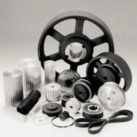 treament: Anodizing, Blackening, Zinc Plating, Phosphatiing


