XWD Cyclo-Getriebe mit Motor – Einstufiges horizontales Fußgetriebe

XWD single-stage horizontal foot-mounted cyclo gear reducer with integrated motor coupling. Frame sizes 1 through 11, center heights 100 mm to 420 mm, output shafts 25 mm to 140 mm. Ratios from 9:1 to 87:1 for direct motor-driven applications in conveyor systems, packaging lines, fans, and pumps. GCr15 bearing steel cycloidal internals, cast iron housing, h6 shaft tolerance. Supplied by Korea Ever-Power with motor matching assistance.
Produktübersicht
Der XWD cyclo gear reducer is a single-stage horizontal foot-mounted cycloidal speed reducer configured for direct motor integration. Unlike the basic XW/BW models that ship as standalone reducer heads requiring separate motor installation, the XWD cyclo gear reducer with motor arrives with the motor-to-reducer interface pre-configured: an IEC-standard input flange, a matched coupling arrangement, and bolt hole patterns ready for immediate motor attachment. This saves the end user from sourcing and aligning a separate coupling assembly on site.
The XWD spans frame sizes 1 through 11, with center heights from 100 mm up to 420 mm. Output shaft diameters range from 25 mm (Frame 1) to 140 mm (Frame 11), and available ratios cover 9:1 through 87:1 in single-stage configuration. The series accepts motor power ratings from fractional kW up to 55 kW, making the XWD horizontal foot-mounted cycloidal gearbox suitable for everything from small packaging conveyor drives to medium-duty aggregate handling systems.
This model serves as a dimensional replacement for Sumitomo CHHM single-stage motor-equipped equivalents. We state this cross-reference purely for selection convenience; Korea Ever-Power manufactures these units under its own brand and quality system. The XWD is part of the broader Zyklongetriebe product family that includes single-stage, double-stage, foot-mounted, and flange-mounted configurations. Korean, Japanese, and Southeast Asian industrial facilities regularly specify the XWD cyclo drive reducer for applications demanding reliable torque delivery with minimal vibration and long maintenance intervals.
Technische Spezifikationen
Der XWD cycloidal speed reducer shares its internal dimensions and shaft geometry with the XW series (standalone reducer head) and the BWD series (foot-mounted motor-ready). The key distinction is the input configuration: the XWD includes a motor mounting flange and coupling arrangement as part of the unit. Below are the critical dimensions for frame selection. Output shaft tolerance is h6; input shaft tolerance varies by frame and motor size.
XWD Installation and Shaft-End Dimensions - Representative Frames (mm)
| Rahmen | Mittelhöhe | A1 | A0 | B1 | B0 | S | D1 (Ausgabe) | B1 | l1 | D2 (Eingang) | B2 |
|---|---|---|---|---|---|---|---|---|---|---|---|
| 1 | 100 | 25 | 90 | 40 | 150 | M8 | 25 | 8 | 34 | 15 | 5 |
| 2 | 100 | 58 | 90 | 42 | 165 | M8 | 30 | 8 | 40 | 15 | 5 |
| 3 | 120 | 69 | 110 | 55 | 240 | M8 | 35 | 10 | 56 | 18 | 6 |
| 4 | 140 | 73 | 150 | 60 | 280 | M10 | 45 | 14 | 71 | 22 | 6 |
| 5 | 160 | 78 | 200 | 75 | 340 | M12 | 55 | 16 | 80 | 30 | 8 |
| 7 | 240 | 39 | 380 | 90 | 420 | M16 | 90 | 25 | 120 | 45 | 14 |
| 9 | 325 | 80 | 500 | 120 | 630 | M20 | 120 | 32 | 165 | 55 | 16 |
| 11 | 420 | 122 | 330x2 | 160 | 800 | 2-M20 | 140 | 36 | 210 | 70 | 20 |
Hinweis: Welle d1/D2 tolerance is h6. Motor flange dimensions (JV column) vary by motor frame size. Full data for all 11 frames available on request.
Gear Ratio Selection and Motor Matching for the XWD
Selecting the correct ratio and motor size for the XWD horizontal foot-mounted cyclo drive requires working backward from the application requirements. Start with the output side: what speed and torque does your driven equipment need? Then calculate the motor and ratio combination that delivers those values within the XWD's operating envelope.
Step-by-Step Selection Process:
1. Determine required output speed (rpm) from the driven machine specifications.
2. Calculate required output torque: T = (Force x Radius) for rotary loads, or T = (Belt pull x Drum radius) for conveyors.
3. Compute the reduction ratio: i = Motor speed / Required output speed. For a 4-pole motor at 1500 rpm driving a conveyor at 35 rpm, i = 1500/35 = 42.9:1. Select the nearest available ratio (e.g., 43:1).
4. Calculate required motor power: P = (T x naus) / (9550 x η), where η = 0.87 for single-stage XWD.
5. Select the XWD frame whose rated torque exceeds your calculated torque by a service factor of 1.25 (uniform load) to 1.75 (heavy shock).
For Korean installations, motors are typically 380V/50Hz three-phase induction type. The XWD cyclo gear reducer accepts both 4-pole (1500 rpm) and 6-pole (960 rpm) motors. For input power above 18.5 kW, the 6-pole option is recommended because the lower input speed reduces centrifugal forces on the eccentric bearing and extends the maintenance interval. Our engineering team can provide a complete motor and reducer package quote. If your driven equipment uses a Antriebswelle connection, include the joint working angle in your inquiry so we can verify output shaft radial load capacity.
Common Engineering Mistakes When Specifying Cyclo Reducers
Based on our two decades of supporting industrial customers in Korea and across Asia, these are the most frequent specification and installation errors we see with Zykloidgetriebe applications. Avoiding these mistakes from the start saves time, money, and unplanned downtime.
Mistake 1: Selecting frame size based on motor power alone, without calculating actual output torque. A 7.5 kW motor at ratio 11:1 produces a very different output torque than the same motor at ratio 71:1. Always calculate torque at the output shaft.
Mistake 2: Ignoring service factor for shock loads. A conveyor carrying uniform sand loads and a conveyor handling random stone lumps require different service factors even if the average torque is identical. Under-specifying the service factor leads to premature bearing fatigue.
Mistake 3: Neglecting output shaft radial load limits. When a heavy Ritzel und Kette assembly hangs on the output shaft, the chain pull creates a significant radial force. If this force exceeds the shaft bearing rating, an outboard bearing support must be added.
Mistake 4: Using incorrect lubricant viscosity for the operating temperature. Standard 40# oil at -15°C ambient (Korean winter, outdoor installation) becomes too viscous to circulate, starving the bearings. Always match oil grade to actual site temperature range.
Mistake 5: Skipping the initial 100-hour oil change. During the break-in period, metal particles from the bearing and disc surfaces accumulate in the oil. Failing to drain and replace after the first 100 hours accelerates wear on all internal components.
Mistake 6: Assuming the XWD cyclo gear reducer self-locks under load. It does not. If the output shaft supports a vertical load or inclined conveyor, install a separate brake or backstop. Without one, the load will backdrive the reducer when power is cut.
XWD Cyclo Gear Reducer vs Bevel Gear Reducer: Choosing the Right Mechanism for Your Shaft Layout
Engineers sometimes consider bevel gear reducers as alternatives to the XWD horizontal foot-mounted cyclo gear reducer because both can deliver moderate reduction ratios in compact housings. However, these two technologies solve fundamentally different geometry problems. A bevel gearbox changes the axis of rotation by 90 degrees (or another fixed angle), while a Zykloidgetriebe maintains collinear input and output shafts. Selecting between them starts with the shaft arrangement your machine requires.
| Parameter | XWD Cyclo Reducer | Bevel Gear Reducer |
|---|---|---|
| Shaft Arrangement | Collinear (input and output on same axis) | Right-angle (90-degree turn) |
| Einstufiger Übersetzungsbereich | 9:1 bis 87:1 | 1:1 to 5:1 (single pair) |
| Effizienz | 85-92% | 93-97% (single pair) |
| Shock Load Capacity | Kurzzeitige Überlastung bis zu 500% | 150-200% (tooth root stress limit) |
| Noise Character | Broadband, low tonal content | Distinct gear mesh whine |
| Maintenance Focus | Oil changes only | Oil changes + tooth contact pattern checks |
| Optimale Anwendungspassung | Inline drives: conveyors, mixers, pumps | Right-angle drives: mills, extruders, mixers needing direction change |
Der XWD cyclo gear reducer with motor is the straightforward choice when the motor and driven equipment are aligned on the same axis. It achieves ratios up to 87:1 in a single stage, something a bevel reducer cannot approach without adding a secondary helical or planetary stage. The bevel gearbox earns its place when the machine layout physically requires a 90-degree turn in the power path, such as when the motor must be oriented perpendicular to a vertical agitator or a horizontal mill roll.
In applications where both inline and right-angle layouts are technically feasible, the XWD cycloidal gearbox generally offers better shock load protection and lower long-term maintenance costs. Bevel gears, while highly efficient for their gear pair, are sensitive to misalignment and require periodic tooth contact pattern checks that cycloidal units do not need. If your application requires a right-angle output and high shock tolerance, a combination of a Zyklongetriebe with an external bevel adapter or right-angle coupling can deliver the best of both mechanisms.

Noise and Vibration Performance
Der XWD cycloidal pinwheel reducer produces a distinctive noise profile that differs from conventional gear reducers. In a standard helical or bevel gearbox, the dominant noise source is the gear mesh frequency: a tonal whine at a pitch determined by the number of teeth and the rotational speed. This tonal noise carries well and is often the most noticeable sound in a quiet plant environment.
In a cycloidal mechanism, there is no traditional gear mesh. The cycloidal disc rolls against pins in a continuous, multi-point contact pattern that generates broadband noise rather than a single tonal peak. The result is a "rushing" or "humming" sound that tends to blend into ambient plant background noise rather than standing out as a distinct whine. At rated load and speed, the XWD cyclo gear reducer with motor typically measures between 60 and 72 dB(A) at one meter from the housing surface, depending on frame size and input speed.
For vibration, the multi-tooth contact pattern distributes dynamic forces across a larger bearing surface than a single-pair gear mesh, resulting in lower peak vibration amplitudes. This makes the XWD a good fit for applications near vibration-sensitive processes such as precision weighing stations, optical inspection systems, and laboratory environments. If your application compares the XWD against a Planetengetriebe on vibration criteria, note that both produce relatively low vibration, but the cycloidal unit handles shock loads better without transmitting impact spikes to the driven equipment.

Verwandte und kompatible Produkte
Der XWD cyclo gear reducer ships as a reducer unit ready for motor attachment. Korea Ever-Power can supply the complete assembly including motor, or the reducer only if you prefer to source the motor locally. Complementary products for complete drive systems:
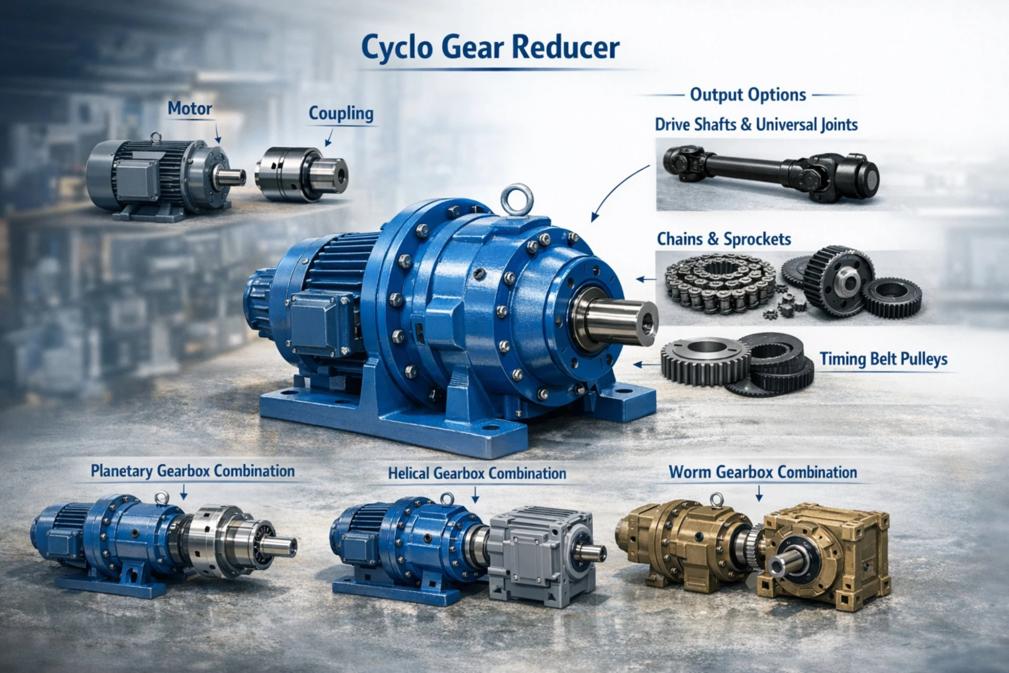
Motor packages with IEC standard flanges from 0.12 kW to 55 kW, three-phase 380V/50Hz, 4-pole or 6-pole configurations. Flexible jaw couplings and motor adapter flanges are included when ordering the motor-reducer package.
Output-side accessories: keyed couplings, chain drive sprocket sets, belt pulleys, and outboard bearing supports for heavy radial loads. For applications needing self-locking on the output, a Schneckengetriebe stage can be added in series downstream of the XWD.
Double-stage expansion: if your ratio requirement later increases beyond 87:1, the XWD housing can be replaced with an XWED double-stage unit on the same foundation, or a pre-stage gearbox can be added upstream without changing the existing driven equipment connection.
Häufig gestellte Fragen
What is the difference between the XWD and the BWD cyclo gear reducer?
Both are single-stage horizontal foot-mounted models with the same internal cycloidal mechanism. The XWD designation indicates the unit is configured with an integrated motor-mounting flange and coupling arrangement. The BWD may be supplied as a reducer head only or with a motor depending on configuration. In practice, many suppliers use XWD and BWD interchangeably for motor-ready horizontal foot-mounted models.
Can I use a VFD (variable frequency drive) with the XWD cyclo gear reducer with motor?
Yes. The XWD pairs well with VFD-controlled motors for variable speed applications. The cycloidal mechanism operates smoothly across the entire speed range without the backlash issues that some gear types exhibit at low speeds. However, when running the motor at speeds significantly below rated (below 25% of nominal), the motor's cooling fan effectiveness decreases. Consider a motor with forced ventilation for continuous low-speed operation.
How do I match the XWD horizontal foot-mounted cycloidal gearbox to an existing motor on site?
Provide us with the motor frame size (e.g., IEC 100L, 132M), shaft diameter, and power rating. We will confirm the correct XWD input flange configuration and coupling. In most cases, standard IEC motor frames from B3 (foot mount) and B5/B14 (flange mount) are directly compatible.
Is the XWD cyclo gear reducer suitable for outdoor installations exposed to Korean weather conditions?
Standard units are rated for -10°C to +40°C ambient. For outdoor installations in northern Korean regions where winter temperatures drop below -10°C, specify synthetic low-temperature gear oil. For rain exposure, an IP55 motor enclosure and enhanced reducer shaft seals are recommended. The housing can also be specified with anti-corrosion epoxy coating for coastal or humid environments.
What is the expected noise level at the operator's position?
At one meter from the housing, the XWD typically measures 60 to 72 dB(A) depending on frame size and speed. At a typical operator distance of 3 to 5 meters, the level drops to roughly 50 to 62 dB(A), which is generally below the threshold requiring hearing protection in Korean workplace safety standards (85 dB(A) continuous exposure limit).
Kundenrezensionen
Lim Jae-hyuk, Conveyor Design Engineer, Gimpo Logistics Center (February 2025)
"Specified XWD Frame 5 with a 5.5 kW motor at 43:1 ratio for eight parcel sorting conveyors. The pre-configured motor flange saved us about 2 hours of alignment work per unit compared to buying a separate reducer and coupling. All eight units have been running two shifts for seven months, zero maintenance interventions beyond the initial oil change."
Hayashi Kenji, Facility Manager, Nagoya Food Processing (January 2025)
"The XWD-3 units on our bottle line conveyors are noticeably quieter than the old helical gearboxes. The operators on the packing floor commented on the difference within the first week. Good product. Delivery to Japan was 10 days."
Yoon Chang-ho, Project Buyer, Sejong Industrial Engineering (March 2025)
"We ordered 15 XWD units across five different frame sizes for a cement plant conveyor system. Every unit arrived correctly configured and matched to the motor spec we provided. The cross-reference accuracy against the Sumitomo models being replaced was exact. We found all the specs and dimensional data on cyclogearreducer.top before placing the order, which made our engineering review much faster."
Tran Duc Minh, Operations Manager, Long An Packaging Co., Vietnam (December 2024)
"XWD Frame 2 with 1.5 kW motor, ratio 29:1, for a carton sealing machine line. Small, compact, runs smooth. We bought four units and all perform identically. The VFD compatibility was tested and confirmed on our Siemens drives without any issues."
Seo Yeon-ji, Maintenance Planner, Ulsan Petrochemical Complex (November 2024)
"We switched from worm reducers to XWD cyclo units on several cooling tower fan drives. Energy monitoring showed an 18% reduction in electricity consumption on those drives. The payback period on the replacement investment was under 14 months. Planning to convert the remaining fans next maintenance shutdown."
Verpackung und Versand

Zusätzliche Informationen
| Editor | Cxm |
|---|
Ähnliche Produkte
-

Zykloidgetriebe der XW BW-Serie – Einstufiges horizontales, fußmontiertes Stiftradgetriebe
-

XLED Zweistufiges Zykloidgetriebe – Vertikal flanschmontiertes Zykloidgetriebe
-

BLED Zweistufiges vertikales flanschmontiertes Cyclo-Getriebe
-

BWED Zweistufiges Cyclo-Getriebe – Horizontales Fußgetriebe
-

XWED Zweistufiges Zykloidgetriebe – Flanschmontiertes Zykloidgetriebe
-

Zykloidgetriebe der XLD-Serie – Vertikal flanschmontiertes Zykloidgetriebe
-

BLD Vertikal-Zyklo-Getriebe für Misch- und Rührgeräte
-

BWD Cyclo-Getriebeuntersetzungsgetriebe – Horizontales, fußmontiertes Getriebe


