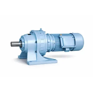
BWD 旋风减速机 – 卧式底座安装齿轮箱

The BWD series cyclo gear reducer delivers ratio ranges from 1:9 to 1:87 in a single-stage horizontal foot-mounted configuration. Designed as a direct replacement for Sumitomo CHHM and SM-Cyclo models, this unit features cast iron housing, GCr15 bearing steel internals, and output torque up to 29,400 N.m. Available in frame sizes 09 through 18, the BWD cycloidal speed reducer fits conveyors, mixers, and general industrial drives across Korean manufacturing facilities. Contact Korea Ever-Power for specifications, pricing, and same-week dispatch on standard models.
Product Overview
一个 旋翼齿轮减速器 is a type of speed reduction device that uses an eccentric bearing to drive a cycloidal disc, producing high torque output at reduced rotational speeds through rolling contact between the disc and a ring of pins. The BWD series represents the single-stage, horizontal foot-mounted configuration within this product family, and it is one of the most widely installed 摆线齿轮减速器 types across Korean and East Asian manufacturing plants.
This unit serves as a direct replacement for Sumitomo CHHM and SM-Cyclo equivalent frame sizes. Customers ordering the BWD cyclo gear reducer can cross-reference their existing Sumitomo frame numbers to find a matching Ever-Power unit with identical shaft dimensions, mounting bolt patterns, and center heights. This cross-referencing is provided solely for customer convenience in selecting the correct replacement unit, and does not imply the sale of counterfeit goods or any affiliation with the referenced brand.
The BWD series covers frame sizes 09 through 18, with center heights ranging from 80 mm to 420 mm. Output shaft diameters span from 22 mm (Frame 09) up to 140 mm (Frame 18), and the housing is precision-machined cast iron for long-term dimensional stability. Input power ratings range from fractional kilowatt motors up to 55 kW, making this horizontal foot-mounted cycloid reducer suitable for light-duty packaging lines as well as heavy-duty aggregate conveyors. Industries that regularly specify this model include cement processing, wastewater treatment, food production, textile manufacturing, and port logistics across South Korea, Japan, and Southeast Asia. View all available models in the 旋翼齿轮减速器 series.
Every BWD unit ships with a standard oil-bath lubrication system, four-bolt foot mounting pads, and keyed input and output shafts machined to h6 tolerance. Optional configurations include a double output shaft variant, a flange-mount adapter kit, and custom RAL color painting for facility standardization.
Technical Specifications and Dimensional Data
The tables below present the complete installation and shaft-end dimensions for all BWD cycloidal speed reducer frame sizes. When selecting a frame, pay close attention to the center height (which determines alignment with your driven equipment), the output shaft diameter d1 and keyway width b1 (which must match your coupling or sprocket bore), and the mounting bolt hole spacing A1 and B1. All dimensions are in millimeters. Shaft tolerances are machined to h6 for the output side and js6 or k6 for specific configurations as noted in the second table.

Table 1: Appearance and Installation Dimensions (mm)
| Frame | 中心高度 | Installation Dimension | Shaft End Dimension | ||||||||||||||
|---|---|---|---|---|---|---|---|---|---|---|---|---|---|---|---|---|---|
| 一个1 | 一个0 | B1 | B0 | h | s | Hole | Output Shaft | Input Shaft | |||||||||
| n | d0 | d1 | b1 | c1 | l1 | d2 | b2 | c2 | l2 | ||||||||
| 09 | 80 | 17 | 76 | 30 | 120 | 12 | M8 | 4 | 11 | 22 | 6 | 24.5 | 30 | 15 | 5 | 17 | 25 |
| 10 | 100 | 58 | 90 | 35 | 150 | 14 | M8 | 4 | 11 | 30 | 8 | 33 | 35 | 15 | 5 | 17 | 22 |
| 11 | 120 | 69 | 110 | 55 | 240 | 16 | M8 | 4 | 16 | 35 | 10 | 38 | 56 | 18 | 6 | 20.5 | 35 |
| 12 | 140 | 73 | 150 | 60 | 280 | 20 | M10 | 4 | 16 | 45 | 14 | 48.5 | 71 | 22 | 6 | 24.5 | 40 |
| 13 | 160 | 78 | 200 | 75 | 340 | 25 | M12 | 4 | 17 | 55 | 16 | 59 | 80 | 30 | 8 | 33 | 55 |
| 14 | 200 | 53 | 320 | 90 | 340 | 25 | M12 | 4 | 22 | 70 | 20 | 74.5 | 102 | 35 | 10 | 38 | 60 |
| 15 | 240 | 39 | 380 | 420 | 420 | 32 | M16 | 4 | 22 | 90 | 25 | 95 | 120 | 45 | 14 | 48.5 | 70 |
| 16 | 290 | 45 | 480 | 80 | 560 | 35 | M20 | 4 | 26 | 100 | 28 | 106 | 140 | 50 | 14 | 53.5 | 82 |
| 17 | 325 | 80 | 500 | 120 | 630 | 40 | M20 | 4 | 30 | 120 | 32 | 127 | 165 | 55 | 16 | 59 | 100 |
| 18 | 420 | 122 | 330x2 | 160 | 800 | 50 | 2-M20 | 6 | 32 | 140 | 36 | 148 | 210 | 70 | 20 | 74.5 | 120 |
Note: Matching tolerance of shaft d1/d2 is h6.
Configuration Drawing - Single Stage Horizontal Type

Table 2: BWD/BW Contour and Installation Dimensions (mm)
| Frame | Contour Dimensions (mm) | Installation Dimensions (mm) | Shaft End Size (mm) | ||||||||||||||||||||||
|---|---|---|---|---|---|---|---|---|---|---|---|---|---|---|---|---|---|---|---|---|---|---|---|---|---|
| M | W | Z1 | Z2 | 我 | X | JV | P | E | R | F | 问 | T | S | N | G | H | B | T | D | L | b | c | d | r | |
| 10 | 110 | 140 | 182 | 129 | 114 | 127 | Per motor | 80 | 74 | 35 | 12 | 115 | 36 | M4 | 4 | 11 | 80 | 6 | 20.5 | 18js6 | 28 | 5 | 16 | 14js6 | 25 |
| 12 | 120 | 185 | 215 | 165 | 190 | 168 | 90 | 93 | - | 15 | 150 | 35 | M8 | 4 | 11 | 100 | 8 | 33 | 30js6 | 35 | 5 | 17 | 15js6 | 22 | |
| 15 | 160 | 250 | 262 | 200 | 260 | 210 | 120 | 120 | - | 18 | 210 | 50 | M8 | 4 | 15 | 120 | 10 | 38.5 | 35k6 | 56 | 6 | 22.5 | 20js6 | 30 | |
| 18 | 230 | 290 | 335 | 260 | 300 | 245 | 180 | 125 | - | 20 | 240 | 60 | M8 | 4 | 15 | 140 | 14 | 49 | 45k6 | 75 | 8 | 28 | 25js6 | 40 | |
| 22 | 280 | 330 | 393 | 311 | 350 | 290 | 220 | 155 | - | 20 | 290 | 65 | M10 | 4 | 17 | 160 | 16 | 60 | 55k6 | 90 | 8 | 33 | 30js6 | 45 | |
| 27 | 380 | 400 | 462 | 359 | 430 | 350 | 320 | 153 | 65 | 25 | 340 | 70 | M12 | 4 | 22 | 200 | 20 | 76 | 70米6 | 100 | 10 | 38.5 | 35k6 | 60 | |
| 33 | 440 | 470 | 545 | 432 | 520 | 420 | 380 | 155 | 100 | 32 | 420 | 80 | M16 | 4 | 22 | 240 | 24 | 97 | 90米6 | 116 | 14 | 49 | 45k6 | 70 | |
| 39 | 520 | 560 | 668 | 528 | 605 | 500 | 440 | 200 | 150 | 35 | 500 | 90 | M20 | 4 | 26 | 280 | 28 | 108 | 100m6 | 140 | 16 | 55 | 50k6 | 80 | |
| 45 | 600 | 690 | 783 | 594 | 706 | 580 | 500 | 245 | 150 | 45 | 630 | 105 | M24 | 4 | 28 | 325 | 28 | 116 | 110米6 | 165 | 16 | 60 | 66k6 | 82 | |
| 55 | 810 | 880 | 966 | 733 | 880 | 735 | 330x2 | 322 | - | 50 | 800 | 140 | M33 | 6 | 36 | 420 | 36 | 140 | 130m6 | 200 | 20 | 76 | 70k6 | 105 | |
| 65 | 900 | 1030 | 1120 | - | 1008 | 855 | 375x2 | 354 | - | 55 | 920 | 170 | M36 | 6 | 40 | 490 | 40 | 171 | 150m6 | 240 | 24 | 87 | 80k6 | 130 | |
How a Cycloidal Speed Reducer Works
The BWD horizontal foot-mounted cyclo drive reducer operates on an eccentric input principle rather than conventional involute gear meshing. The motor-driven input shaft carries an eccentric bearing, which causes a cycloidal disc (sometimes called a cycloid gear) to orbit inside a fixed ring of pins mounted to the housing. As the disc orbits, its lobed profile maintains rolling contact with each pin in sequence. Because the disc has one fewer lobe than the ring has pins, each full revolution of the input shaft advances the disc by exactly one pin position relative to the housing.
This small angular advance per input revolution is what produces the high reduction ratio. For a disc with 20 lobes and a ring with 21 pins, the single-stage ratio is 1:20. The output shaft connects to the cycloidal disc through a set of output rollers fitted into holes on the disc, converting the disc's wobbling orbital motion into smooth concentric rotation. Because nearly half of the pins are in contact with the disc at any given moment (compared to only one or two teeth meshing in a spur gear train), the load is distributed across many contact points simultaneously. This results in significantly higher shock load capacity and a much longer fatigue life for the internal components.
Key engineering point: The rolling contact between the cycloidal disc and pins generates far less friction heat than the sliding contact in worm gear sets. This is the primary reason a BWD cyclo gear reducer maintains 85-92% efficiency at rated load, while worm reducers with comparable ratios typically operate between 40-70%.
The BWD housing also incorporates a two-stage sealing system at both shaft exits: an inner oil seal retains lubricant, and an outer dust lip prevents abrasive particles from entering the bearing area. For the horizontal foot-mounted configuration, lubrication is handled by an oil bath, with the oil level visible through a sight glass on the housing side. The breather cap on top equalizes internal pressure during temperature changes. When the output connects to a chain-driven conveyor, matching 链轮和链条 must be sized to handle the reducer output torque.
Cyclo Gear Reducer vs Worm Gear Reducer: An Engineering Comparison
Both cycloidal and worm gear reducers can deliver high reduction ratios in a single stage. However, their internal mechanisms produce very different performance characteristics. A 蜗轮减速器 transmits power through sliding contact between a helical worm screw and a bronze wheel, while a horizontal foot-mounted 旋翼齿轮减速器 like the BWD uses rolling contact between a cycloidal disc and hardened steel pins. This fundamental difference in contact mechanics drives most of the performance gaps outlined below.
| Comparison Factor | Cyclo Gear Reducer (BWD) | 蜗轮减速器 |
|---|---|---|
| Transmission Efficiency | 85-92% | 40-85% (ratio dependent) |
| Single Stage Ratio Range | 1:9 to 1:87 | 1:5 to 1:100 |
| Contact Type | Rolling (low friction) | Sliding (high friction) |
| Heat Generation | 低的 | High (especially at high ratios) |
| Shock/Overload Tolerance | 最高可达 500% 瞬时过载 | Limited (bronze wheel damage) |
| Self-Locking Capability | No (requires brake) | Yes (at ratios above ~1:30) |
| 典型使用寿命 | 10-20 years (rolling fatigue) | 5-10 years (wear dependent) |
| Noise Level at Rated Load | 60-75 dB(A) | 55-70 dB(A) |
| Backdriveability | Freely backdriveable | Non-backdriveable at high ratios |
The efficiency difference is the most consequential factor for facilities running drives around the clock. A worm reducer operating at a 1:60 ratio typically achieves around 55-65% efficiency, meaning 35-45% of motor energy converts to heat rather than useful output torque. The same 1:60 ratio in a cycloidal unit runs at roughly 87% efficiency, reducing wasted energy by more than half. Over a three-year period on a 15 kW motor running two shifts per day, this efficiency gap translates to meaningful electricity cost savings, often enough to offset the initial price difference between the two reducer types.
The one area where worm reducers hold a clear advantage is self-locking. At ratios above approximately 1:30, a worm set cannot be backdriven through the output shaft, which provides a built-in holding function for vertical lifting applications. A cycloidal pinwheel reducer does not self-lock and will require a separate brake or holding device if the load must remain stationary when power is removed. For horizontal conveyor drives, crane travel mechanisms, and mixer agitators where self-locking is not required, the cycloidal option delivers better efficiency and longer service intervals. For applications that need both high ratio and positioning accuracy, a planetary gearbox may also be worth evaluating.
Selection and Sizing Guide for BWD Cyclo Reducers
Selecting the correct BWD cyclo gear reducer frame size requires four primary parameters from the application. Gathering these before contacting our engineering team will speed up the quotation process and reduce the risk of mis-sizing.
- Required output torque (N.m) or the load weight and radius for lifting/conveying applications
- Required output speed (rpm) or the desired reduction ratio
- Motor power (kW) and motor speed (typically 1500 rpm 4-pole or 960 rpm 6-pole in Korea)
- Mounting orientation: horizontal foot, vertical flange, or double-shaft through-drive
Torque Calculation Method
The basic output torque formula for any speed reducer is: T出去 = (P x 9550 xix η) / n在, where P is motor power in kW, i is the reduction ratio, η is the efficiency (use 0.87 for single-stage cyclo), and n在 is motor input speed in rpm. For example, a 7.5 kW motor at 1500 rpm driving a BWD frame with a 1:43 ratio produces approximately: (7.5 x 9550 x 43 x 0.87) / 1500 = 1,785 N.m at the output shaft.
Environmental and Installation Considerations
Beyond torque and speed, also confirm: the ambient temperature range (standard lubricant suits -10 to +40 degrees Celsius; extreme temperatures require special oil grades), whether the unit operates continuously or in start-stop cycles (service factor adjustment), the presence of corrosive or dusty atmospheres (optional enhanced sealing or surface coating), and the maximum allowable radial and axial loads on the output shaft (if coupling or sprocket loads are significant, an outboard bearing support may be needed). If your application requires self-locking capability, a 蜗轮减速器 may be a better fit for that specific requirement. For applications above 18.5 kW input power, we recommend matching the BWD with a 6-pole 960 rpm motor rather than a 4-pole 1500 rpm motor to reduce internal bearing loads and extend the maintenance interval. The product category page includes ratio selection charts for each frame size.

Core Performance Advantages of the BWD Horizontal Foot-Mounted Cyclo Gear Reducer
► High Torque Density
Output torque from 48.3 N.m to 29,400 N.m across the frame range, with a torque-to-weight ratio that outperforms conventional helical gearboxes of similar capacity by 30-40%.
► Overload Resilience
Multi-tooth contact distributes shock loads across the entire pin ring. Momentary overloads up to 500% of rated torque are absorbed without permanent deformation of the cycloidal disc.
► Extended Service Intervals
Rolling contact generates minimal wear debris. Oil change intervals are 5,000 hours or 6 months for standard duty. Internal components routinely last 10-20 years without replacement.
► Bidirectional Operation
The BWD design permits forward and reverse rotation without modification. This suits reversible conveyor drives, reciprocating actuators, and any process requiring periodic direction changes.
► Compact Footprint
The coaxial input/output arrangement and internal planetary motion keep the housing diameter smaller than an equivalent-ratio helical reducer. Frame 12, for instance, fits within a 200 mm x 320 mm base area while delivering 45 mm output shaft capacity.
Related and Compatible Products
The BWD cyclo gear reducer is one component in a complete power transmission chain. Depending on your application, you may need some of the following complementary products. Korea Ever-Power supplies all of these either from stock or on short lead times, and our engineering team can help you specify the complete drive package.
Power input components: Electric motors (IEC standard frame, three-phase induction) and flexible jaw couplings or pin-and-bush couplings for vibration isolation between the motor and reducer input shaft.
Output-side components: Drive shafts and universal joints for transmitting torque to offset or angular loads, particularly in heavy-duty mixer and kiln applications.
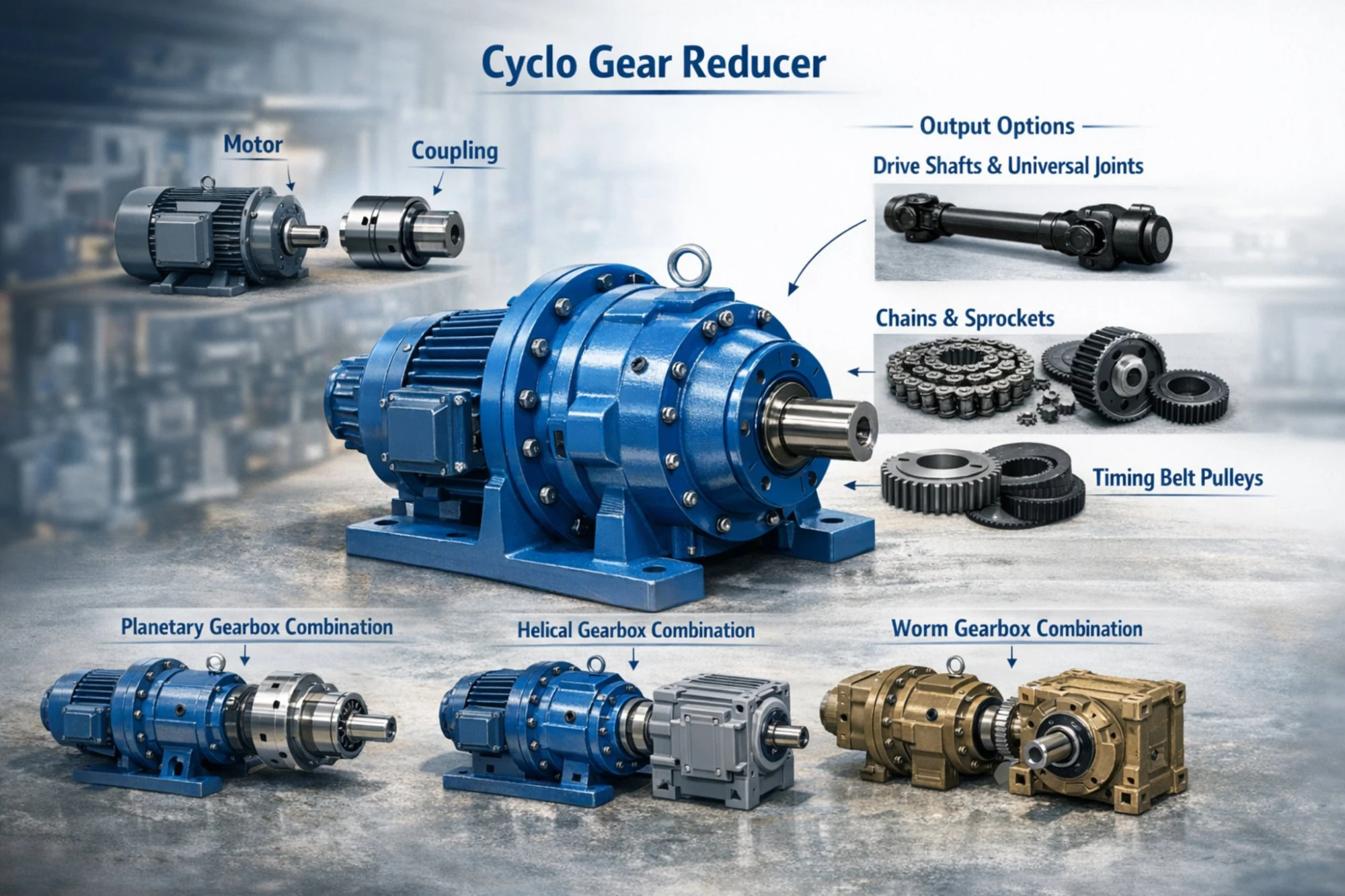
Chain transmission: Sprockets and chains for applications where the reducer output connects to a chain-driven conveyor or bucket elevator.
Combined transmission packages: For applications needing very high reduction ratios (above 1:87), the BWD can be connected in series with a planetary gearbox as a pre-stage or post-stage unit. It can also be paired with a worm gear reducer for applications requiring both high ratio and self-locking capability. Contact us for combined drive arrangement drawings.
Frequently Asked Questions
What reduction ratios are available for the BWD horizontal foot-mounted cyclo gear reducer?
The BWD series offers single-stage ratios from 1:9 to 1:87. For ratios above 1:87, a double-stage BWED model or a BWD combined with an external pre-reduction stage can reach ratios up to 1:7,569.
Is a cyclo reducer more efficient than a worm gearbox for conveyor applications?
Yes. At a typical conveyor ratio of 1:30 to 1:50, a cycloidal unit operates at approximately 87% efficiency, while a worm set at the same ratio typically drops to 60-70%. This difference directly reduces your electricity costs and motor heat buildup.
What lubricant should I use for the BWD series?
Standard operating temperatures call for 40# or 50# mechanical oil. For improved wear protection and longer drain intervals, 70# or 90# extreme-pressure gear oil is recommended. Change oil after the first 100 hours of operation, then every 6 months (based on an 8-hour daily work cycle).
Can the BWD handle shock loads from crusher or vibrating screen applications?
The multi-tooth engagement of the cycloidal disc allows momentary peak loads up to 500% of rated torque without damage. For continuous heavy shock duty, select one frame size above the torque calculation result to provide additional safety margin.
What is the maximum tilt angle for horizontal mounting?
The BWD foot-mounted unit should be installed within 15 degrees of horizontal. Beyond that angle, oil-bath lubrication may not reach all bearings properly, and a circulating oil system or alternative lubrication arrangement becomes necessary.
How long does a cycloidal speed reducer typically last in continuous industrial service?
With proper lubrication and within rated load conditions, the internal components of a BWD cyclo reducer have an expected service life of 10 to 20 years. The bearings are typically the first component to require replacement, and they can be changed without scrapping the housing or cycloidal disc.
Can the BWD be paired with a drive shaft for angular connections?
是的。对于输出需要以一定角度传递扭矩的应用,BWD 输出轴通过一个连接点连接。 drive shaft 以及万向节组件。这在搅拌机、窑炉和输送机等应用中很常见。
韩国永动力公司是否提供OEM贴牌或定制轴配置?
是的。我们提供定制输出轴直径、键槽修改、特殊法兰样式、非标准RAL油漆颜色以及OEM铭牌服务。定制配置的最低订购量通常较低,交货周期为2至4周,具体取决于修改范围。
用户评价
朴俊书仁川钢铁加工公司维修主管(2025年1月)
“我们用Ever-Power BWD Frame 15减速机替换了卷材定长生产线上的四台住友SM-Cyclo减速机。由于轴尺寸相同,因此每台设备的更换耗时不到一天。经过八个月的两班制运行,未出现任何问题。油液保持清洁,没有温度峰值。与购买原装住友替代产品相比,节省了约40%的成本。”
田中宏大阪包装公司工程经理(2025年3月)
“我们订购的BWD-12机组做工精良。噪音明显比之前使用的蜗轮蜗杆减速机低。从订单确认到运抵大阪港只用了9天。”
李秀妍庆南化学工厂厂长(2024年12月)
“我们需要一台配备非标准110mm输出轴的BWD-17,用于我们的反应堆搅拌器驱动。Ever-Power公司定制加工了该轴,并在3周内交付。该装置已连续运行约4个月,负载约为85%。环境温度稳定在55摄氏度左右,完全符合我们的预期。他们的技术团队响应迅速,第一次就提供了正确的联轴器规格。”
阮文清胡志明市水泥公司采购员(2025年2月)
“价格非常有竞争力。我们为斗式提升机驱动装置购买了12台BWD-13和BWD-14。包装很结实,到货时完好无损。只有一台缺少通气帽,但他们免费加急寄来了替换件。”
金惠媛忠清北道食品加工厂设备工程师(2024年10月)
“我们在两条传送带上将减速机从蜗轮减速器更换为BWD旋流减速器。这两条生产线的能耗读数下降了约22%。仅此一项就足以证明此次采购的合理性。我们将在下个季度完成剩余四条生产线的改造。已经开始浏览了。” cyclogearreducer.top 下一批。”
佐藤贤二名古屋纺织厂技术采购员(2024年11月)
“我们为纱线卷绕机订购了BWD-10和BWD-11型号的机器。运行平稳安静,振动水平完全符合我们的规格要求。我们很满意韩国仓库发货的选项,这使交货时间缩短至仅5天。”
为什么选择韩国永力
- 拥有超过20年的动力传输设备制造经验
- 通过 ISO 9001 认证的生产体系,原材料全程可追溯
- 带有CE标志的产品符合国际法规
- 工厂直销,无中间商
- 我们拥有专业的工程团队,提供选型支持、扭矩计算和驱动系统设计服务。
- 韩国国内仓库备有常用尺寸的镜框,可实现当周发货。
- 提供低起订量的OEM和ODM服务
- 完整的传动解决方案:来自同一供应商的旋翼减速器、电机、联轴器、链条、链轮和驱动轴

包装和运输

附加信息
| 编辑 | CXM |
|---|