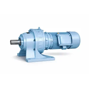
XLD系列摆线齿轮减速器——立式法兰安装摆线齿轮箱

XLD series cyclo gear reducer in vertical flange-mounted configuration. Covers frame sizes 1 through 11 with output shaft diameters from 28 mm to 130 mm. Single-stage and double-stage models available for ratios up to 1849:1. Designed for space-constrained installations where foot mounting is impractical, the XLD cycloidal speed reducer bolts directly to machine frames, vessel flanges, and structural platforms. Cast iron housing, GCr15 internal gears, h6 shaft tolerance. Ships from Korea Ever-Power with standard models in stock for rapid delivery across Korea, Japan, and Southeast Asia.
Product Overview
The XLD cyclo gear reducer is a flange-mounted variant designed for vertical or angular mounting configurations where a traditional foot-mounted base is either impractical or unnecessary. While the BWD/BW series sits on a flat surface and bolts down through feet, the XLD attaches through a circular flange pattern and hangs from or bolts onto a machine frame, vessel wall, or structural platform. This gives mechanical designers more freedom in positioning the drive assembly relative to the driven equipment.
The XLD product line covers frame sizes 1 through 11. On the smaller end, Frame 1 has a 160 mm flange diameter with a 28 mm output shaft, weighing just 8 kg and suitable for light conveyor drives or small agitator systems. At the upper end, Frame 11 reaches an 880 mm flange diameter with a 130 mm output shaft, weighing 210 kg and capable of driving heavy industrial mixers, kiln rotation systems, and aggregate processing equipment. This range makes the XLD flange-mounted cycloidal gearbox a popular choice across a wide spectrum of Korean industrial applications from semiconductor cooling tower drives in Gyeonggi-do to cement plant rotary systems in Gangwon-do.
The XLD cycloidal speed reducer is dimensionally equivalent to corresponding Sumitomo CHHJ and SM-Cyclo flange-mounted models, allowing direct bolt-in replacement. This information is provided purely for customer cross-referencing purposes and does not indicate any affiliation with or endorsement by the referenced manufacturer. Korea Ever-Power manufactures these units independently under our own quality control system. The XLD is one of over 20 models in the 旋翼齿轮减速器 series.
All XLD units feature GCr15 chromium bearing steel cycloidal discs hardened to HRC 58-62, precision-ground alloy steel pin rings, and HT200 cast iron housings machined to tight concentricity tolerances. Output shaft tolerance is held to h6 standard. Both single-shaft and double-shaft (through-drive) output configurations are available across most frame sizes.
Technical Specifications and Dimensions
The following tables present the installation and shaft-end dimensions for the XLD cyclo gear reducer series. The flange bolt circle diameter (D1) and number of bolt holes determine how the reducer attaches to your equipment frame. The output shaft diameter (d1) and keyway width (b1) determine coupling compatibility. All output shaft tolerances are h6 unless otherwise noted.

Table 1: XLD Installation and Shaft-End Dimensions (mm)
| Frame | Installation Dimension | Shaft End Dimension | ||||||||||||||
|---|---|---|---|---|---|---|---|---|---|---|---|---|---|---|---|---|
| D1 | D2 | E | h | R | s | Hole | Output Shaft | Input Shaft | ||||||||
| n | d0 | d1 | b1 | c1 | l1 | d2 | b2 | c2 | l2 | |||||||
| 1 | 134 | 110 | 48 | 9 | 3 | M8 | 4 | 12 | 28 | 8 | 31 | 35 | 15 | 5 | 17 | 25 |
| 2 | 160 | 130 | 42 | 12 | 3 | M8 | 6 | 12 | 25 | 8 | 28 | 34 | 15 | 5 | 17 | 25 |
| 3 | 200 | 170 | 50 | 15 | 4 | M8 | 6 | 12 | 35 | 10 | 38 | 45 | 18 | 6 | 20.5 | 35 |
| 4 | 230 | 200 | 79 | 15 | 4 | M10 | 6 | 12 | 45 | 14 | 48.5 | 63 | 22 | 6 | 24.5 | 40 |
| 5 | 310 | 270 | 93 | 20 | 4 | M12 | 6 | 12 | 55 | 16 | 59 | 79 | 30 | 8 | 33 | 45 |
| 6 | 360 | 316 | 92 | 22 | 5 | M12 | 8 | 16 | 65 | 18 | 69 | 80 | 35 | 10 | 38 | 54 |
| 7 | 390 | 345 | 114 | 22 | 5 | M12 | 8 | 36 | 80 | 22 | 85 | 98 | 40 | 12 | 43 | 65 |
| 8 | 450 | 400 | 112 | 30 | 6 | M16 | 13 | 22 | 90 | 25 | 95 | 110 | 45 | 14 | 48.5 | 70 |
| 9 | 520 | 455 | 170 | 35 | 8 | M20 | 13 | 22 | 100 | 28 | 106 | 129 | 50 | 14 | 53.5 | 80 |
| 10 | 590 | 520 | 174 | 40 | 10 | M20 | 13 | 22 | 110 | 28 | 116 | 140 | 55 | 16 | 59 | 100 |
| 11 | 800 | 680 | 210 | 45 | 10 | 2-M20 | 13 | 28 | 130 | 32 | 137 | 184 | 70 | 20 | 74.5 | 120 |
Note: Matching tolerance of shaft d1/d2 is h6.
Table 2: XLD Outer Contour and Weight (mm / kg)
| Frame | D (Outer Diameter) | L (Double Shaft) | L1 (Flange Style) | Weight (kg) |
|---|---|---|---|---|
| 1 | 160 | 202 | 141 | 8 |
| 2 | 180 | 218 | 155 | 13 |
| 3 | 230 | 269 | 191 | 26 |
| 4 | 260 | 333 | 255 | 38 |
| 5 | 340 | 399 | 302 | 93 |
| 6 | 400 | 470 | 358 | 138 |
| 7 | 430 | 522 | 397 | 160 |
| 8 | 490 | 581 | 440 | 240 |
| 9 | 580 | 698 | 529 | 370 |
| 10 | 650 | 806 | 608 | 622 |
| 11 | 880 | 1022 | 811 | 210 |
Single Stage vs Double Stage Cyclo Reducer: How to Choose the Right Configuration
The XLD flange-mounted cyclo gear reducer is offered in both single-stage (XL) and double-stage (XLD) versions. Deciding between them comes down to one primary question: what output speed and reduction ratio does your application require? Both share the same housing footprint and flange bolt pattern for each frame size, so the external mounting interface remains unchanged regardless of whether you select single or double stage.
| 范围 | Single Stage (XL) | Double Stage (XLD) |
|---|---|---|
| Ratio Range | 9:1 至 87:1 | 99:1 至 7,569:1 |
| Output Speed (at 1500 rpm input) | 17 to 167 rpm | 0.2 to 15 rpm |
| Overall Efficiency | 85 - 92% | 72 - 85% |
| Housing Length (typical Frame 5) | Shorter (single disc set) | Longer (two disc sets in series) |
| Weight (same frame) | Lighter | 15-25% heavier |
| Typical Application | Conveyors, fans, pumps, standard drives | Slow-speed kilns, digesters, heavy agitators |
A single-stage XL cycloidal gearbox is the better choice when your target output speed falls between roughly 17 and 167 rpm (assuming a standard 4-pole 1500 rpm motor). Single-stage units cost less, weigh less, and run at higher efficiency because the power passes through only one cycloidal disc-and-pin set. Most belt conveyor drives, ventilation fan drives, and general-purpose machine drives operate in this speed range and are well-served by single-stage reduction.
A double-stage XLD cycloidal speed reducer becomes necessary when the target output speed drops below approximately 15 rpm or when the required ratio exceeds 87:1. In a double-stage arrangement, the output of the first cycloidal set feeds into the input of the second cycloidal set within the same housing, compounding the ratios. This means a first stage at 29:1 followed by a second stage at 29:1 yields an overall ratio of 841:1, producing an output speed of about 1.8 rpm from a 1500 rpm motor. Double-stage units are commonly found on rotary kiln drives, sludge digester stirrers, and ultra-slow-speed turntable applications.
Quick selection rule: If your required ratio is below 87:1, choose single stage (XL). If it is above 99:1, choose double stage (XLD). Ratios between 87:1 and 99:1 fall in a gap where either configuration may work. Contact our engineering team for guidance in this overlap zone. For even higher ratios beyond 7,569:1, the XLD can be connected in tandem with a planetary gearbox pre-stage.

Energy Efficiency and Operating Cost Impact
The efficiency of a speed reducer directly affects electricity bills and motor sizing. A reducer running at 90% efficiency converts 90% of motor input power into useful output torque, while the remaining 10% becomes waste heat. A less efficient reducer, such as a worm type at 60% efficiency, wastes 40% of motor power as heat. For facilities running multiple drives around the clock, this difference adds up quickly.
Consider a real calculation: a single 11 kW motor running a 摆线减速器 at 88% efficiency for two shifts per day (16 hours), 300 days per year. The annual energy wasted as heat is: 11 kW x 0.12 x 16 h x 300 d = 6,336 kWh. If that same drive used a worm reducer at 62% efficiency instead, the waste energy climbs to: 11 kW x 0.38 x 16 h x 300 d = 20,064 kWh. At a Korean industrial electricity rate of approximately 120 KRW per kWh, the annual saving per drive is roughly 1,647,360 KRW (about 1,250 USD). Across ten drives in a typical production facility, the combined annual saving exceeds 12,000 USD purely from reduced electricity waste.
Beyond electricity savings, higher efficiency also means smaller motors can be specified for the same output torque requirement. This reduces motor purchase cost, starter/VFD sizing, and cable cross-section requirements. The XLD flange-mounted cyclo gearbox maintains its efficiency advantage across the entire ratio range, unlike 蜗轮减速器 where efficiency degrades sharply at higher ratios.
Installation and Commissioning Steps
Proper installation is critical for reaching the rated service life of any cycloidal pinwheel reducer. Follow this sequence when installing the XLD cyclo gear reducer for the first time or when reinstalling after maintenance.
- Inspect the mounting flange surface on both the reducer and the receiving frame. Remove any burrs, paint buildup, or debris. The flange faces must be flat and parallel to within 0.1 mm across the full bolt circle.
- Lift the reducer into position using appropriately rated rigging attached to the lifting eyebolts (provided on Frames 5 and above). For smaller frames, manual handling is acceptable with two workers.
- Insert mounting bolts through the flange holes and tighten in a star pattern to the torque values specified in the installation manual for each bolt size (M8 through M20 depending on frame).
- Connect the motor to the input shaft using a flexible coupling. Align radial offset to within 0.05 mm and angular misalignment to within 0.5 degrees. Use dial indicators or laser alignment tools for accuracy. If a drive shaft is used between the reducer output and driven equipment, verify the universal joint working angles are within specification.
- Fill with lubricating oil through the breather cap opening. Use 40# or 50# mechanical oil for standard conditions, or 70#/90# EP gear oil for extended service intervals. Fill to the center of the sight glass.
- Run the unit unloaded for 30 minutes. Check for abnormal noise, vibration, oil leaks at shaft seals, and housing temperature. The housing surface should not exceed 70 degrees C during this break-in run.
- Connect the load and run under partial load (50-75%) for the first 4 hours. Monitor temperature and vibration. After confirming stable operation, increase to full rated load.
- Drain and replace oil after 100 hours of initial operation. This first oil change removes metal particles generated during the break-in period.

Related and Compatible Products
The XLD cycloidal gear reducer integrates into complete drive systems alongside these companion products, all available from Korea Ever-Power:
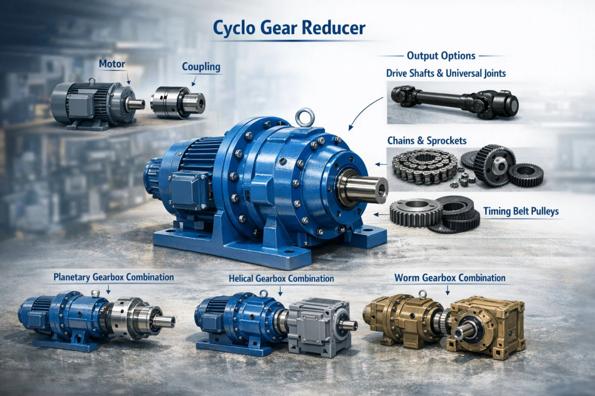
- Electric motors: IEC standard flange and foot-mounted, three-phase induction, 0.12 kW to 315 kW
- Flexible couplings: Jaw type, pin-and-bush, and disc couplings for vibration isolation
- Drive shafts and universal joints for angular torque transmission
- Sprockets and roller chains for chain-driven output connections
- Planetary gearboxes for series connection to achieve ultra-high ratios beyond 7,569:1
- Worm gear reducers for applications requiring self-locking holding capability
Frequently Asked Questions
What is the difference between the XLD and XL flange-mounted cyclo gear reducer models?
XL denotes the single-stage flange-mounted model with ratios from 9:1 to 87:1. XLD denotes the double-stage version with ratios from 99:1 to 7,569:1. Both mount using the same flange bolt pattern for a given frame size.
Can I replace a foot-mounted BWD with a flange-mounted XLD on existing equipment?
Yes, but the mounting interface is different. You would need to fabricate a mounting bracket or adapter plate that converts from foot mounting to flange mounting. The internal cycloidal mechanism and performance are equivalent between BWD and XLD at the same frame size.
Should I choose single stage or double stage for a belt conveyor running at 25 rpm?
At 25 rpm output from a 1500 rpm motor, the required ratio is 60:1, which falls within the single-stage XL range (9:1 to 87:1). A single-stage unit will be lighter, more efficient, and less expensive than a double-stage unit for this application.
Can the XLD output connect to a chain drive system?
Yes. The keyed output shaft pairs directly with standard 链轮和链条 for conveyor, elevator, and material handling applications. Size the sprocket bore to match the XLD output shaft diameter from the table above.
What is the maximum axial load the XLD output shaft can handle?
Axial load limits vary by frame size. In flange-mounted vertical installations where the output shaft supports a hanging load (such as an agitator impeller), the shaft bearings handle both torque and impeller weight. For loads exceeding the standard bearing capacity, we supply an external thrust bearing support kit. Contact our engineering team with your specific load figures for proper sizing.
How often should I change the oil in the XLD series cyclo gear reducer?
First oil change at 100 running hours, then every 6 months for standard 8-hour daily operation or every 3 to 4 months for continuous 24-hour duty. Use 40# or 50# mechanical oil at standard temperatures, or 70#/90# EP gear oil for better protection and longer intervals.
Does the XLD produce less noise than a helical gearbox at the same ratio?
At equivalent ratios and loads, cycloidal reducers and helical gearboxes produce similar noise levels (60-75 dB(A) range). The cycloidal unit tends to have a smoother, less tonal noise character because it lacks the periodic gear tooth meshing frequency that helical units produce. In practice, the noise difference is minor and unlikely to be the deciding factor between the two types.
Customer Feedback
Han Ji-hoon, Project Engineer, Seoul Automation Systems (February 2025)
“我们为一条包装生产线的改造指定使用XLD Frame 6单元。法兰安装座可以直接用螺栓固定在现有机器框架上,无需任何适配板。这为我们节省了制造时间和成本。这些单元已经连续运行五个月,每天16小时,没有任何问题。”
铃木武福冈港物流公司维护协调员(2025年1月)
“我们的集装箱堆垛起重机行走驱动装置采用XLD-8型液压缸。7个月以来,由于突然启动和停止造成的冲击载荷并未引起任何问题。此前,我们同样的设备每12-14个月就要更换一次蜗轮蜗杆的铜轮。根据目前的状况,我们预计液压缸的使用寿命会更长。”
尹素拉釜山海洋设备采购经理(2025年3月)
“订购了五台XLD设备,一周内就送到了釜山。包装非常好。我特别欣赏的一点是,铭牌上清楚地标明了混合比、序列号和油品类型,这使得维护记录变得非常简单。”
加藤惠美静冈纺织制造厂厂长(2024年12月)
“我们染色机驱动装置上的XLD-3和XLD-4单元运行极其平稳。振动水平符合原厂规格。价格与日本国内品牌相比极具竞争力,而且根据我们过去一年的经验,质量也与之相当。”
陈明德越南平阳工业区运营工程师(2024年11月)
“我们为低速旋转式干燥机购买了XLD-9双级电机。输出转速为2.8转/分,在不同的负载条件下,扭矩输出始终保持稳定。在报价过程中,Ever-Power团队帮助我们计算了正确的传动比和服务系数,避免了我们自己选型时可能出现的错误。”
我们的制造工厂
每一个 XLD flange-mounted cyclo gear reducer 该设备在我们配备数控加工中心、热处理炉、坐标测量机和专用装配洁净室的生产基地制造。我们通过了ISO 9001认证的质量管理体系,涵盖原材料来料检验、加工过程公差检查、齿轮硬度验证、装配后设备的噪声和振动测试,以及发货前的最终涂装和包装检验。
所有产品的年产能均超过5万台。 旋翼驱动减速器 产品系列。标准 XLD 车架(1 至 8 号,常用比例)备有成品库存,可快速发货,通常在订单确认后 3 至 5 个工作日内发货。较大尺寸的车架和非标准配置的交货周期为 2 至 4 周。我们在仁川的韩国联络处负责为韩国客户协调当地的物流事宜。产品详情和技术资料下载请访问[此处插入链接]。 cyclogearreducer.top.

包装和运输

附加信息
| 编辑 | CXM |
|---|